Search for broadband signals ground-based radio navigation system

Author: Musonov V.M., Romanov A.P.
Journal: Siberian Aerospace Journal @vestnik-sibsau-en
Section: Informatics, computer technology and management
Article in issue: 3 vol.23, 2022.
Free access
In the present paper, a method of temporary search for broadband of frequency manipulation with minimal shift keying (MSK) signals of ground-based radio navigation systems (RNS) is considered. The method is based on a multi-alternative optimal signal detection (the signal may belong to one of the orthogonal signals) using the evaluation-correlation principle of processing (ECPP) under conditions of a priori uncertainty. The problem of representing broadband MSK signal as a signal with double discrete frequency-phase modulation (FPM) was solved. The law of phase manipulation in the form of a binary sequence of elements lb of a length code τ э L (in the “Sprut” RNS, 16383 L , 2.5 э mcs is the duration of the signal element) is defined through the law of frequency manipulation in the form of a binary sequence of elements ld of a known length L code. The representation of the signal in the form FPM allows, during correlation processing, to replace the correlation integral on the interval [0, τ]э L by L the sum of correlation integrals on the intervals [0, τ]э or by L the sum of element-by-element correlations. The calculation of element-by-element correlations allows the use of a matrix apparatus for the ECPP of the analyzed signal. With the technical implementation of the “search” procedure, there is no need to form 2L pairs of reference quadrature signals with the length L of the modulating code, and instead of that a pair of element-by-element correlations is memorized and over time τэ , according to a code element lkd , cyclically shifted by 1 k elements, frequency manipulation and a code element klb , cyclically shifted by 1 k elements, phase manipulation, block-by-block accumulation L of quadrature correlations is performed. The use of upper-left and lower-right triangular matrices with binary elements klb makes it possible to search for broadband MSK signal with additional phase manipulation of a discrete information message. The structure of the optimal algorithm of parallel search for ECPP of the broadband MSK signal with the use of a matrix apparatus, which allows to implement the optimal algorithm “of search” during the duration τэ L of the signal in real time.
Signals with frequency-phase manipulation, quadrature correlations, element-by-element correlations, binary matrix, upper (lower) triangular matrix
Short address: https://sciup.org/148329636
IDR: 148329636 | UDC: 631.365.22 | DOI: 10.31772/2712-8970-2022-23-3-391-408
Text of the scientific article Search for broadband signals ground-based radio navigation system
In radio systems where broadband signals (hereinafter referred to as signals) are used to position and track moving objects (radio navigation) time measurements prove to be a key procedure. In radio navigation systems (RNS), by means of signals’ searching and auto-tracking, the moments of response time of both elements and the received signal itself are determined. In this case, the local time reference of the mobile unit must be appropriately synchronized with the received reference station (RS) signals.
The synchronization process of the receiving part of the onboard station (BS) consists of two stages. During the first stage, the search and capture of signals transmitted by the RS is carried out; during the second stage - tracking the signal, the parameters of which (time delay, carrier frequency, initial phase) can randomly change in time. The search for a signal is carried out in time, since the moment of signal occurence is in a-priori unknown, as well as in terms of frequency, which can be shifted eather due to the Doppler Effect or to instability, and is not exactly known at the receiving point. Thus, the synchronization-related actions of the signal receiver incorporate preliminary adjustment of its own reference signal to the received signal and maintaining synchronism between them during the entire subsequent signal reception. To match the local reference signal with the received signal, the time shift of the received signal relative to the local reference signal should be measured, and the local receiver generator is corrected in time for the measured time shift, thereby the search for the received signal code occurs. This means that one of the main tasks of the primary signal processing in the RNS is to search for such a signal parameter as the code delay by the delay time. Thus, the main task of this study is to develop an algorithm that allows optimally provide "search".
Broadband Search Methods
In modern broadband RNS, for the formation of broadband signals (BBS), mainly phase shift keying (PSK) of the carrier oscillation is used with a binary code sequence of maximum length (as an example) ( M -sequence of length L = 2 m - 1, m - bit width of the forming register). Solving the problem of searching for BBS with phase manipulation has received serious attention from many researchers. Many works are devoted to the problem of searching for signals with PSK, of which [1–4] should be noted. Despite the ultimate clarity of measurement issues, as well as fundamental works on optimal indice, many questions of signal search still remain open. Today, the problem of building a synchronization device with maximum speed, providing the search for PSK signals by delay with large and very large lengths of code sequences ( L > 10 3 ...10 5 ) has been solved. Known algorithms [5] for fast PSK discrete signals search can significantly reduce the search time through lowering the number of calculations (algebraic additions) from magnitude L2 to magnitude m = L log2 L by multiplying the column matrix with L element-by-element correlations via the Walsh-Hadamard orthogonal basis matrix presented in factorized form (product of m weakly filled matrices). The above algorithms cannot be used to search for signals with additional PSK transmitted via discrete message in the form of binary symbols { Dr }. In this case, the column matrix may contain two groups of computed element-by-element correlations. The first group will correspond to the end of the symbol fragment Dr corresponding to the additional PSK; the second group will correspond to the beginning of the symbol fragment D r + 1. When D r + 1 ^ Dr , then the element-by-element correlation groups will be unequal in sign, which does not allow the use of these algorithms.
The main task when using BBS in the RNS is to measure the delay time of the received signal. The measurement accuracy of the delay time is determined by the effective frequency of the BBS spectrum and the signal-to-noise ratio [6]. The effective A f э frequency of the BBS spectrum is determined primarily by the clock frequency F T = 1/ тэ, which determines the frequency band A f , corresponding to the passage of a signal with a given power level. Thus, at a 90% power level for a signal with PSK ( A f 0 1,7 F T ( A f э □ 0,33 F T ), and for a signal with frequency shift keying at a minimum shift (MSK), it will be 2.2 times less [7]. To work with a PSK signal in the frequency band of the MSK signal, it is necessary to reduce it by a factor of 2.2, while the effective frequency of the PSK spectrum of the signal will be A f э = 0,33 F T /2,2 which is 27% less than the effective frequency of the spectrum for the MSK signal. Additionally, during the work of temporary tracking system with a PSK signal, the variance of the fluctuation time tracking error will increase by more than 4.8 times due to a decrease in the steepness of the discrimination characteristic of the BBS of the PSK signal relative to the MSK [8].
Thus, in the marine RNS of the medium wave range with a limited frequency resource, the most acceptable signals are those with MSK (orCPFSK in the English abbreviation) [9] which, as shown above, have a high spectral efficiency. Considerably fewer publications are devoted to the search for broadband signals with MSK [10; 11]. The implementation of a parallel search for BBS with the length L > 104 of the modulation frequency shift keying code with a minimum shift and with an additional PSK transmitted discrete message in the form of binary symbols {Dr} is currently not available in the literature.
Formation of broadband signals with MSK
The structure of the search algorithm for a broadband signal with MSK (hereinafter referred to as the signal) is based on the representation of the signal element with frequency shift keying in continuous phase [12] on the interval {t l } = [ l тэ, ( l + 1)т э ] by the following expression:
s l ( t ) = A cos
Ш o t +
d l n m f [ t - ( l - 1)тэ ]
э
l - 1
+n mf E dj j=1
where A - amplitude; шo - central frequency; l - the subsequent number of the signal element on the interval [lтэ,(l + 1)тэ ]; dl - the binary symbol according to which the frequency-shift keying is performed. For a frequency-shift keying with minimum shift mf = 2Д f тэ = 0,5, where Дf = (fв - fн)/2- frequency deviation; fн(в) = fo+FT /4 manipulated lower (upper) frequencies; FT = 1/ тэ - clock frequency (keying frequency). Assuming that dl g {-1, +1} and yielding in the argument cos(*) from (1) components with frequencies and phase angle, we obtain d>п2Дf т„ t djn(1 -1)т, n l-1, nfV r
ш o t + --------— +---;----- + E d j = 2 n ( fo + d l Д f)t + - E d j + d l (1 - l)
т э 2 т э 2 j = 1 2 L j = 1 J
Now accepting that d l g {0,1} and simplifying the summand with the phase angle, we can rewrite (2) in the form:
2n( f o + d l Д f ) t + -
f l - 1
E d j + d l (1 - 1 )
L j = 1
= 2n( dlf н + d l f в )t + nb l
where bl=1E '=,( dj- d )■
As { d l } - is a sequence of binary elements, it is not difficult to see that for any l and any binary sequence code { d l } the algebraic sum in (4) will be an even number, and then the phase value b l n / 2 will be multiple of n. Taking into account the frequency cos(*), in this case we can say that the phase angle will take the values 0 or n , which is equivalent to b l g {0,1} in (3). In view of what has been said, it is now easy to see that one can use the replacement of the algebraic sum (4) by "sum modulo 2" to "sum modulo 2" of elements dj and dl . Then the consecutive binary element will be determined by the recurrent expression:
f^
b l = E d j - ld l
L j = 1 J
f l
= E ( d j - d l ) ^ ( d 1 Ф d l ) ® ... ® ( d j ® d l ) ® ... ® ( d l ® dl ), (5)
J
l
where dl e {0,1} and bi e {0,1} - are regular binary symbols corresponding to the frequency and phase shift keying of the signal element l . From (5) it follows that the binary symbol bl is determined by the sequence of the first 1, 2,..., l binary symbols d e {d1,d2,...,dl} b1 = d1 Ф d1 = 0, b2 = d1 Ф d2 ® d2 ® d2 = d1 ® d2, b3 = d1 ® d2 ® d3 Фd3 Фd3 Фd3 = d1 Фd2 = b2, b4 = d1 Ф d2 Ф d3 Ф d4 Ф d4 Ф d4 Ф d4 Ф d4 = d1 Ф d2 Ф d3 Ф d4 = b2 Ф d3 Ф d4.
From (6) it is easy to determine the recurrent rule for { bl } (assuming bo = 0):
A J bl—I, b =
1 [ b l _ 2 Ф d l - 1 Ф d l .
для нечётного l для чётного l
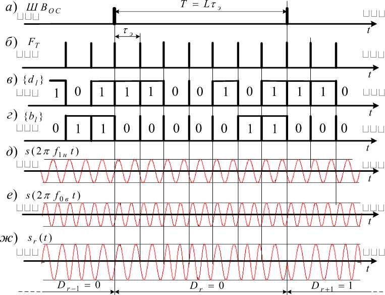
Рис. 1. Фрагменты формирования широкополосного сигнала с ЧММС:
а – временная диаграмма шкалы времени ОС; б – временная диаграмма сигнала тактовой частоты; в – код { dl } манипуляции частоты; г – код { bl } манипуляции фазы; д – гармонический сигнал нижней частоты f 1 н (манипулирующий символ dl = 1); е - гармонический сигнал верхней частоты f 0в (манипулирующий символом dl = 0); ж - ШПС c ЧММС при дополнительной фазовой манипуляции информационными символами Dr - 1 , D r и D r + 1
Fig. 1. Fragments of broadband signal formation with MSK:
a – temporal diagram of the time scale of the fixed station; b – temporal diagram of the clock frequency signal; v – frequency manipulation code { dl }; g – phase manipulation code { bl };
d - the lower frequency f 1 н of the harmonic signal (manipulating symbol dl = 1); e - the upper frequency f 0в of the harmonic signal (manipulating symbol dl = 0); zh - broadband signal MSK signal with additional PSK by information symbols Dr - 1 , Dr и Dr + 1
Taking into account the formation of signal elements (3), broadband signal under frequency shifting (for example) using a binary M-sequence {d }of length L [13] with additional phase shift keying (PSK), the transmitted discrete message Dr g {0,1} can be written in the form sr (t) = AE rect[t - (l - 1)Тэ ] C0S [2n (dlfн + dlfв ) t + П(bl ® Dr )] ,
where rect (*) - pulse of unit amplitude, with duration тэ for the l signal element:
rect[ t - ( l - 1)тэ ]
1, ( l - 1)т э < t < l Т э ,
0, ( l - 1)т э > t и t > l тэ.
According to (7), the binary code { b }, through which phase manipulation is performed, corresponds to a modified binary M -sequence { d }of length L .
Fig. 1. presents the fragments of a seven-element (as an example) broadband signal with MSK formation at the reference station.
Parallel time search method for a broadband signal with MSK
The use of quasi-coherent receivers for processing broadband signal - MSK (hereinafter referred to as signals) requires the introduction of tracking devices into a synchronous mode with an accuracy determined by the capture area of the devices. Usually, the capture area is smaller than the area of uncertainty of the signal parameters (for example, in terms of frequency and signal delay), which implies the search for a signal in the area of uncertainty.
In marine navigation systems, the uncertainty interval in the frequency of the received signal during the search can be neglected due to the small Doppler shift in frequency (the speed of onboard objects is no more than 100 km/h). Therefore, the accuracy of the delay of the received signal during the search should be determined by the corresponding signal correlation interval, which limits the capture area. With an area of uncertainty equal to the duration of the signal T = L тэ , one can choose such a discrete delay interval that will be no less than the area of signal capture in time. It is assumed that the entire delay uncertainty interval is divided into discrete intervals equal to т э . The number of such intervals will be equal to L = T / т э , so the delay uncertainty interval can change discretely. In this case, it is convenient to take the value of the time interval equal to those values of the delay shift at which the analyzed and reference signals are practically orthogonal. Having adopted the model of a discrete change in the delay, we can assume that one of the L quasi-orthogonal signals arrives at the input of the receiving device with a delay that is a multiple of т э .
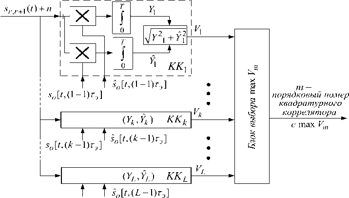
With the adopted model, the search task is reduced to performing detection and recognizing which of the L signals (each differing in the cyclic shift тk = (k - 1)тэ (k = 1, L) of the modulating code sequence {dkl }) operates, making it possible to eliminate the uncertainty in delay, i.e., to determine the cyclic shift тk belonging to the analyzed signal. As is known [14], for the optimal recognition of orthogonal signals L , it is necessary to use a L -channel scheme in which optimal L -ary recognition is carried out and the optimal binary detection procedure is performed for the selected signals. The block diagram of the optimal L-channel recognition of one of the orthogonal signals is shown in fig. 2. The multichannel receiver contains quadrature correlators (QC), each including “ X ” - a signal multiplier; “ J ” - integrators; “ ^Y/2 + Y]2 ” is a nonlinear converter that calculates the value of the correlation modulus Vk of the complex envelopes of the received signal mixture sr r+1(t) together with the fluctuation interference n and the reference signal so [t,(k - 1)тэ ]; “Max selection block Vm ” is the decision block. In the quadrature correlator with number k , the in-phase and quadrature correlations are calculated
s o [ t,(L - 1 T ]
Рис. 2. Оптимальный L -канальный корреляционный приёмник
Fig. 2. Optimal L -channel correlation receiver
TT
Y k = f [ S r , r + 1 ( t ) + n ( t )] S o [ t ,( k - 1)T э ] dt и Y k = f [ S r , r + 1 ( t ) + n ( t )] S o [ t ,( k - 1)T э ]dt ,
where s r , r + 1( t ) - is the analyzed signal, which is most often a sequence of signal elements belonging to the terminal fragment of the first modulating information symbol Dr and the initial fragment of the second modulating information symbol Dr + 1 (Fig. 3). Here, the analyzed signal sr , r + 1( t ) relative to the initial moment of time t 1 1 will be a signal cyclically shifted to the left p - 1 by elements (8).
D r + 1
D r
|
a) p - 1 |
p |
p + 1 |
p + 2 ... L - 2 |
L - 1 |
L |
1 2 ... p - 2| |
p - 1 |
p |
p + 1 |
p + 2 |
|
б)______ |
- T = т э L . |
|||||||||
|
1 |
2 |
3 ... p - 1 |
p |
p + 1 |
p + 2 ... L - 1 |
L |
1 |
2 |
3 |
|
Рис. 3. Эпюры анализируемого и опорного сигналов tL ,1 t1,2 t 2,2 t 3,2
t 1,1 t 2,1 t 3,1
t p ,1 t p + 1,1 t p + 2,1
Fig. 3. Plots of the analyzed and reference signals
In this case, it is convenient to write the expression for the received signal on the interval {t } = [ t 1.1 , t 12] as follows:
L
S r , r + 1 ( t ) = A r E rect [ t - ( l - p ) т э ]cos [M d l f H н + d l f eв ) t + ( b l ® D r ) П + ф r , l J +
I=p p-1
+ A r + 1 E rect [ t - ( L - p + l ) T э ]cos [ 2n ( d l f H н + d l f e в ) t + ( b l ® D r + 1 )n + Ф l , r + 1 J ,
here ф r , l и ф r + 1 , l - are possible phase delays at frequencies f н and f в for “signals” r and r + 1.
Here s o [ t ,( k - 1)т э ] and s o [ t ,( k - 1)т э ] - are quadrature reference signals of unit amplitude with cyclic shifts to the left k - 1 by binary symbols of the modulating code sequence { dl }, acting at the inputs of quadrature correlators (Fig. 3), are determined by the expressions:
-L s0 (t,(k - 1)тэ) = X rect[t- (l - k)тэ ]cos [2п (df( + dlf,)t + bп J + l=k
k
+ ^ rect [ t - ( L - k + 1 - 1)тэ]cos I 2п ( d l f н + d l f в ) t + b l п I , i = 1
L so(t, (k - 1)тэ) = X ™c[t -(l - k)Tэ]sin [2п (dlfн + dlfв ) t+ biп J + l=k
k
+ ^ rect[t - (L - k +1 -1)тэ ] sin I 2n (dlf н + dlf в) t + bl п i=1
.
From the calculated modules V 1 , V 2 , …, Vk , …, VL the decision block selects the module with the maximum value - V m : m = 1, L . Now, to implement the input of tracking devices (by time or by phase) into the synchronous mode, orthogonal signals so [ t ,( m - 1)т э ] and s o [ t ,( m - 1)т э ] with cyclic shifts to the left by m - 1 binary symbols of the modulating code sequences { dl } и { bl }.
Parallel “search” for the signal (8) is performed using the optimal receiver (Fig. 1). The implementation of the optimal receiver (Fig. 1) for a number L 1 is connected to significant difficulties associated with the formation of L pairs of quadrature broadband signals with MSK (12) at the same time and the technical design of quadrature correlators L .
Consider the element-by-element processing of the analyzed signal (8). According to (10) and (12), it is possible to calculate the in-phase and quadrature correlations in QC with a number k applying the formulas
X
L
X X rect k [ t - ( l - 1) т э ] cos Г 2п ( d kl f н l = 1
+ d kl f в ) t + b kl п J dt ,
L^ э L
Y k = f A X rect p [ t - ( l - 1)т э ] cos Г 2п ( d pl f н + d pl f в ) t + ( b pl Ф D r )п + ф l J + n ( t )
0 Г l = 1
X
L
XX rectk [t - (l - 1)тэ ] sin Г2п (dklfн + dklf в ) t + bkl1 п J dt, where the binary elements dlp (blp) and dlk (blk) correspond to the binary symbols of the modulating (by frequency and phase) code sequences cyclically shifted to the left by p -1 and k -1. Correlations Yk and Yˆk will be calculated with ideal (to simplify the analysis) clock synchronization in accordance with the processed signals sr (t), as explained in Fig. 3 and quadrature reference signals so [t, (k -1)тэ ] and so [t,(k -1)тэ ]. Here, the impulse functions coincide at the clock moments, i.e. rectp [*] = rectk [*] = rect [*]. Taking into account the property of additivity under integration [15], the products of sums (11) of synchronous sequences of pulses rect[*] with equal duration, calculation of correlations Yk and Yˆk can be written in terms of Lsums of integrals with integration over intervals {t} = [0, тэ ]:
Yk = A £ ] rect p [ t - ( l - 1)т э ] rect k [ t - ( l - 1)тэ ]cos[2n ( dplf , + dplf в ) t + ( bpl © Dr )п + ф t ] x l = 1 0
x c os[2n ( d kl f н + d kl f в ) t + bu n] dt +
+£ J n[t - (l - 1)тэ ]rectk[t - (l - 1)тэ]cos[2n(duf. + dufв)t + bkln]dt, l=1 0
Y k = A £ J rect p [ t - ( l - 1)т э ] rect k [ t - ( l - 1)S ]cos[2n ( d^f н + d^ в ) t + ( b pl © D r > + ф l ] x l = 1 0
x sin[2n ( dklfн + dklf в ) t + b kl n] dt +
L тэ _
+ £ J n [ t - ( l - 1)т э ] rect k [ t - ( l - 1)т э ]sin[2n ( d kl f н + d kl f в ) t + b kl П dt .
l = 1 0
Applying expansion cos(a + P) = cos(a)cos(P) - sin(a)sin(P) and sin(a + P) = sin(a)cos(P) + + cos(a)sin(P), accepting Dr = 0, assuming that under bpl e 0,1 and bu g 0,1 cos( bp zn) = b*pl e- 1,1 and co s( b ki n) = b ki g- 1,1 , and applying in (14) 2n( d pl f н + dpifв ) = й( d pl ) and 2n( d kl f H + dk i f e ) =
ю(dk), correlations Y and Yk calculated in в CQ with number k will be determined by the following relations:
L т э
Yk = A £ bkib*Pi Jrect[ t- (l - 1)тэ ]cos[®( dpl) t+ф l ]cos[®( dki) t] dt+£ bki ^ kl, l=1 0
L т э
TZ 7*7* Г ,Г, Z 7 1\ T Г/7\,. 1 • Г Z 7 \ ,1 7, . X ' 7 * £
Yk = A £ bkbpl Jrect[ t- (l - 1)тэ ]cos[®( dpi) t + ф l |sln|ю( dki) t] dt + £ bill ^ kl l=1 0
Here t,ki and ^и - are normal random processes [14], corresponding to a certain integral from the product of a harmonic signal, unit amplitude and duration т э, and a random function n (t) in the form of white noise with spectral density No .
In the products cos[a(dpl)t + ф]cos[ш(dkl)t] and cos[a(dpl)t + 9]sin[ro(dkl)t] from (15) the frequency ю(dkl) can take one of two values - юн under dkl = 1or under dkl = 0 . In addition, in case of inequality dkl ^ dpl these products will be equal to zero, since the signals at frequencies юн andюв will be orthogonal in the enhanced sense [16], but under dki = dpi - have the values тэ cos(ф) / 2 and тэ sin(ф) / 2. Neglecting the terms with the total frequency, these products will take the following form:
cos[ro( dpl ) t + ф]cos[ro( dkl ) t ] = cos[ro( dpl ) t + ф] x
cos[ro( dpl ) t + ф]sin[ro( dkl ) t ] = cos[ro( dpl ) t + ф] x
cos <® H t ), d kl = 1 cos <® et ), d kl = 0 ' sinio. , t ), d kl = 1 ^т(ю в t ), d ki = 0.
'cos( ф ), d ki = d pi
0, d ki ^ d pi ,
' sin( Ф ), d ki = d pi
0, d ki ^ d pi
= P ( d ki ),
,
= P ( d ki )
the in-phase and quadrature correlations Yk and Y ˆ k can be written in the following form:
Y k =; £ b k i [ x ( d kl ) + ^ kl ], Y k = £ * i [ x ( d kl ) + 1 kl ], (17)
i = 1 i = 1
where
Ат * Ат * .
x(dki) = ^э (bpi ® Dr )р(d^) and x(da) = (bpl Ф Dr )p(d^ ), §kl и §kl - signal and interference quadrature element-by-element correlations (EC). Denoting ¥(dkl) = x(dkl) + §kl and ¥(dkl) = x(dkl) + §kl for (17), the correlations and the correlation modulus can be rewritten
LL
Y k = S b kl ¥ ( d kl ), Y k = S b k ¥ ( dk l ) and Vk = ^ k 2 + Yk . (19)
l = 1 l = 1
The structure of the algorithm (19) for calculating the correlation modulus is explained (Fig. 4). By means of each of the adders «^ L » in view of the sign the element-by-element correlations b* ¥(dkl )and b* ¥(dkl) are accumulated; with the accumulation of the L sums, the modules Vk are formed. For clarity, we will also accept n(t) = 0 , therefore, analyzing the work of the scheme (Fig. 4) with respect to the accumulation of element-by-element correlations according to (17)–(19), we can say that the k-th component Yk is calculated as the sum L of the products of symbols b* g-1,1 (belonging to the modified M code of L length cyclically shifted by positions k -1) and element-by-element correlations x(dkl), selected from a pair of values x(1) and x(0) , which are formed simultaneously by two pairs of element-by-element integrators “ τэ ”, corresponding to the 0
correlations of the consecutive element of the analyzed signal s r , r + 1( t ) and harmonic signals, duration
τэ with frequencies ωн and ωв . Here, from each pair l of values x(1) и x(0) by means of commutators (Fig. 4), controlled by l symbol dkl g {0,1}, one of the values of element-by-element correlations x(0) or x(1) is sampled according to the rule
Г x (1), d kl = 1, . Г x (1), d kl = 1,
\ x (0), d kl = 0,, k l I x (0), d kl = 0..
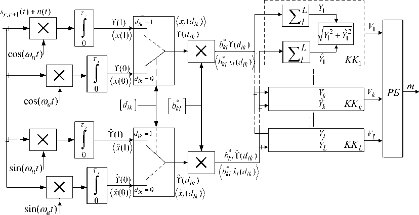
Рис. 4. Структура алгоритма поиска ШПС – ЧММС сигналов
Fig. 4. Structure of the broadband MSK signal search algorithm
By introducing the substitution of indices in dkl = dlk and x ( dkl ) = x l ( dlk ), and denoting b *l as bkl , we obtain the final formulas for calculating the k-th in-phase and quadrature correlations Yk and Y ˆ k :
LL
Y k = Z b kl xl ( d lk ), Y k = £ b kl xl ( d lk ).
Here xt ( dlk ) - the successive l element-by-element correlation formed at the output of the switch controlled by the successive binary symbol d lk , which also belongs to the cyclically shifted by k - 1 M -code of L length.
Search algorithm via matrix representation of the binary signals recognition problem
When considering the formation of a group of values Y 1 , Y 2 , … Yk , … YL of in-phase correlations (21), we can say that the group of values L of in-phase correlations can be represented as a transposed matrix-column Y = || Y , Y 2 ,Y 3 ,...,Y k ,..., YL| T sized L x 1, while each of the matrix elements Y corresponds to the sum L of the products of the binary elements bkl of the k -th row of the matrix B and elementwise correlations xl ( dlk ) of the column matrix X . Here the matrix B is a square matrix of size L x L , where each of the k -th rows represents
B =
|
b 11 |
b 12 . |
.. b 1 l .. |
. b 1 L |
b 1* |
b 2* . |
.. b L * |
|
|
b 21 |
b 22 . |
.. b 2 l .. |
. b 2 L |
b 2* |
b 3* . |
.. b 1* |
|
|
bk 1 |
b k 2 . |
.. b kl . |
.. bkL |
= |
b k * |
b * + 1 . |
.. b k - 1 |
|
bL 1 |
. b L 2 . |
.. b Ll .. |
. bLL |
b L * |
b 1* .. |
.. b L - |
the sequence of binary symbols { bkl }, belonging to the modified M -code { dl }of length L cyclically shifted by k - 1 , formed according to the rule (6)—(7) . To provide calculations with matrix elements B the representation of the elements bkl of the first matrix through the elements of the second matrix is used, which can be expressed in terms of the element number l of the k -th row of the binary sequence{ bk * l }:
*
bkl = bl + k - L 0 - 1 ,
L =1 L , l + k - 1 > L ,
[ 0, l + k - 1 < L .
The column matrix X includes elements L , each corresponding to the subsequent number l of calculated element-by-element correlation value xl ( dlk ) according to the rule (20):
X =
|
x 1 ( d 1 k ) |
X 1 [( d 1 k = 0)] ИЛИХ 1 [(d 1 k = 1)] |
|
|
x 2 ( d 2 k ) |
x 2 [( d 2 k = 0)] или x 2 [( d 2 k = 1)] |
|
|
xl ( dlk ) |
= |
x l [( d lk = 0)] UЛUX l [( d lk = 1)] |
|
x L ( d Lk ) |
x L [( d Lk = 0)] или x L [( d Lk = 1)] |
;
|
x ˆ 1 ( d 1 k ) |
x ˆ 1 [( d 1 k |
= 0)] |
или |
X 1 [( d 1 k = 1)] |
|||
|
x ˆ 2 ( d 2 k ) |
x ˆ2[( d 2 k |
= 0)] |
или |
X 2 [( d 2 k = 1)] |
|||
|
X = |
x ˆ l ( d lk ) |
= |
x ˆ l [( d lk |
= 0)] |
или |
x 1 [( d k = 1)] |
. (24) |
|
x ˆ L ( d Lk ) |
x ˆ L [( d Lk |
= 0)] |
или |
x L [( d Lk = 1)] |
Here, each l value of the element-by-element correlations xl ( dlk ) is determined by the symbol bit value dlk . At number l only l pair of element-by-element correlations (20), formed by a pair of element-by-element integrators (Fig. 4) participates in the formation of l term (21). It should also be noted that from the l pair of element-by-element correlations, the value that is formed at the output of the switch (Fig. 4) is selected in accordance with the value of the bit of the current symbol dlk at the control input of the switch. Under this condition, the selected value of the element-by-element correlation bkl will be summed up in the k -th in-phase (quadrature) correlation Yk ( Y ˆ k ) (20). Here, element-by-element correlations are sampled through symbols dlk , which should be elements of the matrix:
The elements of the first row of the second matrix D
The remaining lines are code sequences {d lk }cyclically shifted by k - 1 elements. To provide calculations with matrix elements D the representation of the elements dlk of the first matrix through the elements of the second matrix is used, which can be expressed in terms of the element number L of the k -th row of the binary sequence { dlk }:
d lk = d l + k - L 0 - 1
J L , l + k - 1 > L , [ 0, l + k - 1 < L .;
Thus, the calculation of the group of values Y1 , Y2 , …Yk , …YL of in-phase correlations (21) can be represented as a product of matrices in expanded form
Y = B x X ; Y = B x X .
Algorithm (27)-(28) must be executed during the signal duration Lt3 . In this case, it is necessary to perform addition operations L 2 . Under L = 16383 and тэ = 2,5 ms (RNS "Sprut"), the duration of the procedure for one addition operation will be тэ / L > 1,5*10 -10 s. It may be said that addition operations should be carried out with a frequency of at least 6,5 GHz. This is too high an operating frequency for the calculator. To reduce the requirements for the operating frequency of the calculator, it is proposed to represent the product of matrices in algorithm (27)–(28) as a product of block matrices [17].
Block matrices are formed by dividing matrices Y , B , X , D M - 1 by horizontal lines, matrices
B , D N - 1 by vertical lines into M x N and M blocks, respectively. Thus, the matrix product (27)
can be expressed in terms of the product of block matrices:
Y 1
Y 2
B 11
Y
m
B M 1
..... B 1 N
в
B m , n .....
..... B M , N
x
Y M
X 1 ( D 1, m )
X 2 ( D 2, m )
X n ( D n , m )
X N ( D N , m )
Л
,
Y ˆ 1
Y ˆ2
ˆ
m
Y ˆ M
B 11
B M 1
..... B1 N B m , n .....
..... B M , N
x
X ˆ 1 ( D 1, m )
X ˆ 2 ( D 2, m )
_A___
X ˆ n ( D n , m )
ˆ
X N ( D N , m )
, (29)
where
Y m = E B m , n X n ( D n , m )
n'
;
Y m = Z B
n'
ˆ
X ˆ n ( D n , m ) –
m – block matrix of in-phase and quadrature correlations; the block matrix B will consist of columns n' = L/ N and m' = L/M rows with the corresponding bkl elements of the first matrix (22):
b k '+ m '(1 - 1), l '+ n '(1 - 1) ... b k '+ m '(1 - 1), l '+ n '( n '-1)
R
B m , n
... b k '+ m '( m - 1), l '+ n '( n - 1) ."
b k '+ m '( m '-1), l '+ n '(1 - 1) ... b k '+ m '( m '-1), l '+ n '( n '-1)
where k ' and l - a are indices denoting the numbers of rows and columns in the block matrix B mn . In this case, the elements of the block matrix B mn can be expressed in terms of the elements bkl of the matrix (23) in the following form bkl = b k ‘+ m(m - 1) l >+ n >( n - 1) . The block matrix of element-by-element correlations with the number of rows n' = L / N and the block matrix D nm with elements corresponding to the elements dlk of the first matrix (25) are shown below.
Y n ( D n , m ) =
y 1 + n '( n -1) ( D n , m )
...
yl '+ n '( n - 1) ( D n , m ) ;
D n , m
d l '+ n '(1 - 1), k '+ m '(1 - 1) ... d l '+ n '( n '- 1), k '+ m '(1 - 1)
... d l '+ n '( n -1), k '+ m '( m -1) ...
d l '+ n '(1 - 1), k '+ m '( m '-1) ... d l '+ n '( n '-1), k '+ m '( m '-1)
y n '+ n '( n -1) ( D n , m )
The use of block matrices to execute algorithm (27) (28) makes it possible to more rationally accumulate quadrature correlations (29). The number of m' lines in the block matrix Bm n is chosen in the way that the interval тэ can be performed via one summation element-by- element correlations for each of the addresses m'. Calculation of each sum of element-by-element correlations is performed in 3 steps (3 cycles): fetching an operand (the accumulated sum of element-by-element correlations, taking into account the sign bkl) from the memory block at the address k‘; addition with the consecutive value of the element-by-element correlation xl ; writing the sum to the memory block at the same address. In a calculator made on an FPGA [18] during τэ it is possible to perform тэ fT = 1625 clock cycles (тэ = 2,5 ps, fT > 650 MHz) or 529 summation operations with writing to “memory”, which will correspond to 529 correlation accumulation or m = 529. The number of block rows in block matrices (27) — (28) correlations will make M = [3L / тэ fT ] = 31, and here each block row will correspond to the adder of element-by-element correlations xl (dlk) taking into account the sign of the elements bkl of the block matrix Bm,n.

D
D r
D
|
s r ± 1( t ) |
■ ' r —1 w 1---------- 1----------------------------► |
r |
◄------------------------------------1 1 |
||||||||||||||||||||
|
uuu p —1 1 |
(5) p |
(6) |
(7) |
T |
(8) L |
(1) |
(2) |
T I |
(3) |
(4) 1P — |
1 |
(5) p |
(6) p +11 |
(7) uuu |
(8) L |
(1) |
(2) 1 и и и |
(3) p — 2 |
(4) p —4 |
(5) p |
|||
|
t 1 x T 1. l ( d l , k ) x T 1.1 ( d 1, k ) |
4-I I b 1 |
b 2 |
b 3 |
T I I |
t 2 b 4 |
r b 5 |
b 6 |
T I I |
b 7 |
b 8 |
t 3 |
b 1 |
1 b 2 |
b 3 |
t 4 b 4 |
b 5 |
T 1 1 |
b 6 |
b 7 |
t 5 b 8 |
xT 2. l ( dl , k ) x T 2.1 ( d 1, k ) |
t |
|
|
x T 1.2 ( d 2, k ) |
b 2 |
b 3 |
b 4 |
I |
b 5 |
b 6 |
b 7 |
I h |
b 8 |
b 1 |
b 2 |
b 3 |
b 4 |
b 5 |
b 6 |
1 |
b 7 |
b 8 |
b 1 |
x T 2.2 ( d 2, k ) |
|||
|
x T 1.3 ( d 3, k ) |
b 3 |
b 4 |
b 5 |
I |
b 6 |
b 7 |
b 8 |
b 1 |
b 2 |
b 3 |
b 4 |
b 5 |
b 6 |
b 7 |
1- |
b 8 |
b 1 |
b 2 |
x T 2.3 ( d 3, k ) |
||||
|
x T 1.4 ( d 4, k ) |
b 4 |
b 5 |
b 6 |
I |
b 7 |
b 8 |
b 1 |
I |
b 2 |
b 3 |
b 4 |
b 5 |
b 6 |
b 7 |
b 8 |
1 |
b 1 |
b 2 |
b 3 |
xT 2.4( d 4, k ) |
|||
|
x T 1.5 ( d 5, k ) x T 1.6 ( d 6, k ) |
b 5 b 6 |
b 6 b 7 |
b 7 b 8 |
I I- |
b 8 b 1 |
b 1 b 2 |
b 2 b 3 |
I I I |
b 3 b 4 |
b 4 b 5 |
b 5 b 6 |
b 6 b 7 |
b 7 b 8 |
b 8 1----- b 1 |
b 1 b 2 |
■| 1 1 |
b 2 b 3 |
b 3 b 4 |
b 4 b 5 |
xT 2.5( d 5, k ) xT 2.6( d 6, k ) |
|||
|
x T 1.7 ( d 7, k ) |
b 7 |
b 8 |
b 1 |
b 2 |
b 3 |
b 4 |
I |
b 5 |
b 6 |
b 7 |
b 8 |
b 1 |
b 2 |
b 3 |
1 |
b 4 |
b 5 |
b 6 |
x T 2.7 ( d 7, k ) |
||||
|
x T 1.8 ( d 8, k ) |
b 8 |
b 1 |
b 2 |
I |
b 3 |
b 4 |
b 5 |
I |
b 6 |
b 7 |
b 8 |
b 1 |
b 2 |
b 3 |
b 4 |
1 |
b 5 |
b 6 |
b 7 |
xT 2.8( d 8, k ) |
|||
Рис. 5. Диаграммы входных сигналов и элементов матриц B и X
Fig. 5. Diagrams of incoming signals and elements of matrices B and X
When searching for a signal with an additional PSK navigation message in binary form Dr a situation may arise in which coherent accumulation becomes impossible. This can be seen when considering Fig. 5, where diagrams of the analyzed signals sr±i (t) under additional PSK navigation message using binary symbols Dr and in accordance with them, the elements of the multiplied matrices B and X are shown. In Fig. 5 signal analysis is performed at intervals {T1} = [t1,13] and{T2} = [13,t5]. On the analysis interval T1 element-by-element correlations are calculated corresponding to the column matrixXT 1 = |xT 1,1(d1,k) xT 1,2(d1,k) ... xT 1,8(d1,k)| , shown on the left. On the analysis interval T2 element-by-element correlations are calculated corresponding to the column matrixXT2 = |xT2,1(d1,k) xT2,2(d1 k) ... xT2,8(d1,k)| , shown on the right. Between the matrices-columns matrices B of binary elements bkl are placed. The analysis interval T1 corresponds to a fragment of the end of the signal from the element number p through L under modulating symbol Dr—1 = 1 (as an example) and a fragment of the beginning of the signal from element 1 through p — 1 under modulating symbol Dr = 0 (as an example). In this case, the calculated element correlations xT 1,l (dl,k) for numbers p ^ L wil be determined with regard to Dr—1 = 1 (18); calculated element correlations for numbers 1 v p -1 will be determined with regard to the symbol value Dr = 0(18). This shows that the signs of the calculated groups of element-by-element correlations (for example, when L = 8 are the calculated first 4 and second 4 element-by-element correlations) will be opposite. If we represent the matrix B as the sum of the left upper triangular matrix B and the right lower triangular matrix Bн, then the correlation matrix Y , calculated on the first interval can be written in a short form
Y t i = B x X t 1 = B e x X T 1 + B h x X r 1 = Y r 1B + Y r 1H (33)
or in the expended form
|
Y T 1 = |
b 11 b 21 b 31 ... |
b 12 b 22 b 32 ... |
b 13 b 23 b 33 ... |
’ • b 1, L - 1 b 1 L ■’ b 2, L - 1 0 |
x |
x T 1.1 ( d 1 k ) x T 1.2 ( d 2 k ) ... x T 1. l ( d lk ) |
+ |
0 0 0 ••• |
0 0 0 • • • |
0 0 0 • • • |
••• 0 ••• 0 • • • b 3, L - 1 ••• ••• |
0 b 2 L b 3 L • • • |
X |
x T 1.1 ( d 1 k ) x T 1.2 ( d 2 k ) ... x T 1. l ( d lk ) |
, (34) |
|
|
• • 0 ..... |
0 ••• |
|||||||||||||||
|
b l - - 1,1 |
b L - 1,2 |
0 |
•• 0 |
0 |
... |
0 |
0 |
b L - 1,3 |
•• b L - 1, L - 1 |
b L - 1, L |
... |
|||||
|
b L ,1 |
0 |
0 |
••• 0 |
0 |
x T 1. L ( d Lk ) |
0 bL 2 |
b L 3 |
•• b L , L - 1 |
b L , L |
x T 1. L ( d Lk ) |
||||||
Where the matrix elements B в and B are determined through (23) by the elements of the matrix B (22). From (34) and Fig.5 it follows that the first group of element-by-element correlations can be taken into account in the first product of matrices B в and X ; the second group of element-by-element correlations can be taken into account in the second product of matrices B н and X .
The analysis interval T also corresponds to a fragment of the end of the signal from the element number p through L now with a modulating symbol D r = 1 (as an example) and a fragment of the beginning of the signal also from element 1 through p - 1 now with a modulating symbol Dr+x = 0 (as an example). In this case, the calculated element-by-element correlations xT 2. l ( dl , k ) for numbers p v L will be determined using the value of the symbol Dr = 1 (18); the calculated element-by-element correlations for the numbers 1 v p - 1 will be determined using the value of the symbol Dr + 1 = 1(18). Hence, the signs of the calculated second groups (third and fourth) of element-by-element correlations (for example, when L = 8 are those calculated first 4 and second 4 element-by-element correlations) will be opposite. If matrix B is represented as the sum of the left upper triangular matrix B в and the right lower triangular matrix B н , then the correlation matrix Y T 2 , calculated on the second interval can be written in short form
Now, based on (33) — (36) it is possible to calculate the correlations corresponding to the interval {t } = [ 1 2 1 4 ] (Fig. 5) of the signal analysis with the full effect of the modulating symbol Dr
YDr = Вн x Xt 1 + Be x XT2 = Yt 1н + Yt2b .(37)
It follows from (35) that the analysis of the signal must be carried out on two successive time intervals { t } and { t }. In the first time interval { t } in-phase and quadrature correlations are calculated according to (33) and (34):
-
Yti,н = Вн x Xti and Yti,н = Вн x Xti ,
in the second time interval { t } in-phase and quadrature correlations are calculated according to (35) and (36):
Yti+1,в = Вв x Xti+1 and Yti+1,в = Вв x Xti+1 .
Thus, in order to implement a parallel signal search algorithm that is invariant to an additional PSK via an information message, the required in-phase and quadrature correlations can be obtained from the calculated quadrature correlations (38) and (39)
Y = Yti, H + Yti+1,в, Y = Yit ,н + Yit+1,в.(40)
Conclusion
As a result, the proposed in this article representation of the broadband signal – MSK as a two-position one with binary frequency-phase shift keying allows through the use of a matrix apparatus in search algorithms to calculate the values of the correlation modules of the complex envelopes of the received signal mixture together with fluctuation interference and the reference signal, which essentially simplifies the implementation of the search algorithm for L ? 1 (16383).
The development of an algorithm for matrix calculations of the correlation modules components of complex envelopes using parallel-sequential accumulation in time greatly simplifies the calculation of the L correlation modules of complex envelopes. When making the necessary calculations on the FPGA, a simultaneous reduction in the FPGA hardware resources is ensured, which allows the search to be carried out practically in a time not exceeding the signal duration, as well as in real time.
The use of the upper left and lower right triangular binary matrices makes it possible to search for broadband signal – MSK during coherent processing and incoherent signal accumulation with additional phase keying of the information message without loss of noise immunity.
References Search for broadband signals ground-based radio navigation system
- Tuzov G. I. Statisticheskaya teoriya priyoma slozhnykh signalov [Statistical theory of complex signal reception]. Moscow, Sovetskoe radio Publ., 1977, 400 p.
- Varakin L. E. Sistemy svyazi s shumopodobnymi signalami [Communication systems with noise-like signals]. Moscow, Radio i svyaz Publ., 1978, 304 p.
- Zhuravlyov V. I. Poisk i sinkhronizaciya v shirokopolosnykh sistemakh cvyazi [Search and synchronization in broadband communication systems]. Moscow, Radio i svyaz Publ., 1986, 241 p.
- Perov A. I. Osnovy postroeniya spytnikovykh radionavigacionnykh system [Fundamentals of building satellite radio navigation systems]. Moscow, Radiotechnika Publ., 2012, 240 p.
- Losev V. V., Brodskaya E. B., Korzhik V. I. Poisk i dekodirovanie slozhnych diskretnykh signalov [Search and decoding of complex discrete signals]. Moscow, Radio i svyaz Publ., 1988, 224 p.
- Ipatov V. P., Kazarinov Yu. M., Kolomenskiy Yu. A. Poisk, obnaruzhenie i izmerenie parametrov signalov w radionavigazionykh sistemakh [Search, detection and measurement of signal parameters in radio navigation systems]. Moscow, Sov. radio Publ., 1975, 296 p.
- Bondarenko V. N. Pomekhoustoychivost priyema spektralno-efektivnykh shumopodobnykh signalov [Noise immunity of receiving spectrally effective noise-like signals]. Krasnoyarsk, Sib. Feder. un-t Publ., 2015, 160 p.
- Bondarenko V. N. [Noise immunity of the noise-like signal time discriminator]. Radiotekhnika. 2009, No. 5, P. 26–33 (In Russ.).
- Makarov S. B., Zykin I. A. Peredacha diskretnykh soobshcheniy po radiokanalam s ogranichenoy polosoy propuskaniya [Transmission of discrete messages over radio channels with limited bandwidth]. Moscow, Radio i svyaz Publ., 1988, 304 p.
- Ipatov V. P. [Search for noise-like signals with minimal frequency manipulation]. Radiotekhnika. 1991, No. 6, P. 47–49 (In Russ.).
- Bondarenko V. N. [A quasi-optimal algorithm for finding a noise-like signal with minimal frequency manipulation]. Izvestiya vuzov Rossii. Radioelektronika. 2007, No. 4, P. 24–31 (In Russ.).
- Osborne W. P., Luntz M. B. Coherent and Noncoherent Detection of CPFSK. IEEE Trans. 1974. Vol. COM-22, No. 8, P. 1023–1036.
- Ipatov V. P. Shirokopolosnye sistemy i kodovoe razdelenie signalov [Broadband systems and code separation of signals]. Moscow, Tekhnosfera Publ., 2007, 487 p.
- Shumopodobnye signaly v sistemakh peredachi informazyi [Noise-like signals in information transmission systems]. Ed. V. B. Pestryakov. Moscow, Radio i svyaz Publ., 1982, 424 p.
- Bronshteyn I. N., Semendyaev K. A. Spravochnik po matematike dlya inzhenerov i uchashchikhsya vuzov [Handbook of Mathematics for engineers and university students. Moscow, Nauka Publ., 1986, 544 p.
- Fink L. M. Teoriya peredachi diskretnykh soobshcheniy [Theory of transmission of discrete messages]. Moscow, Sov. radio Publ., 1975, 727 p.
- Demidovich B. P. Osnovy vychislitelnoy matematiki [Fundamentals of Computational Mathematics]. Moscow, Fizmatgiz Publ., 1963, 660 p.
- Zynq – 7010, Key Featuresand Benefits.
