Self Learning Intelligent Controller of Electro hydraulic Actuator

Author: Ayman A.Aly, Abdallah A. Alshennawy, A.Abo-Ismail, S.Dossokey
Journal: International Journal of Engineering and Manufacturing(IJEM) @ijem
Article in issue: 1 vol.3, 2013.
Free access
The use of electro-hydraulic cylinders in industry has been becoming increasingly popular. A Fuzzy Logic Controller (FLC), which consists of the linguistic defined fuzzy sets and the control rules, is designed to control of the electro-hydraulic cylinder. Using the triangle shaped membership function; the position of the servo cylinder was successfully controlled. When the system working condition is altered, the control algorithm is shown to be more robust compared to the PID controller.
Intelligent Position Control, Fuzzy Logic Control, PID, Electro hydraulic
Short address: https://sciup.org/15014346
IDR: 15014346
Text of the scientific article Self Learning Intelligent Controller of Electro hydraulic Actuator
Published Online June 2013 in MECS DOI: 10.5815/ijem.2013.01.03
Electro hydraulic servodrives are widely used in versatile industrial applications such as machine tools, industrial robots, autonomous manufacturing systems and various actuators in aircraft. They can be applied in closed-loop control systems to achieve accurate force, velocity or position control [1].
In industrial applications, the dynamic characteristics of the servo-hydraulic system are always complex and highly nonlinear. Moreover, there are too many uncertainties in it; for example, the viscosity of oil, the bulk modulus, the oil volume, the system pressure, the wear and the cavitations [2]. The loading conditions are usually rather unsteady, and the loading forces change in a wide range during operation.
When the process is complex and nonlinear with variable parameters, the conventional control theory can not be applied. The modern control theory and adaptive control techniques have been used to control that plant. However, the adaptive control requires accurate mathematical control model or lot of computational effort to estimate and adapt the controller parameters [3]
Hydraulic cylinder system is a nonlinear one with variable parameters. It is difficult to meet control
* Corresponding author. Tel.:
demands or obtain satisfactory performance by adopting traditional PID tuning techniques. An alternative approach to control the complex plant is to investigate the control strategy employed by the human operator. The non-mathematical approach called “Fuzzy Set Theory” [4], [5] is suitable for developing reliable logic controller for plants with wide parameters variations. In this paper, an intelligent Fuzzy controller (IFC) is presented for position control of an electro hydraulic servo.
-
2. Mathematical model and specifications of the system
-
2.1. The Electro hydraulic Servo Valve Transfer Function
The main reasons to use positioning servos in industry are the demands on the accuracy, the stiffness and good dynamic responses to the changes in the command signal or the load.
From Moog Technical bulletin, a convenient form for the servo valve transfer function, [2] is:
Qv(s) Cv
I(s) (1 + TvS f S, + "' X + 1
® v ^ v
where Q v is the valve main stage flow rate, I is the valve input, Cv is the total valve flow gain, T v is the valve time constant and m v , Z v are the undamped natural frequency and damping ratio of the valve respectively.
-
2.2. Hydraulic Actuator Transfer Function
The equations of the servovalve flow to and from the actuator (assuming symmetric valve port, zero lap design and zero return pressure) are as follows,
For Xv > 0
Q f = C ^ WX . sgn( P s - P f ) - Ps - P f , Q n = C d WX v sgn( P n ) - P n
\ p \ p
For Xv < 0
Qf = CdWXv sgn(Pf)J-Pfl , Qn = CdWXv sgn(PS -Pn), -Ps - Pn| V p V p where Xv is the spool displacement, Ps is the supply pressure, p is the mass density of the oil, Cd is the discharge coefficient of the orifice, W is the width of the orifice, suffix n denotes the annular side and suffix f denotes the full side.
The linearized flow equation of the actuator is given by [6]:
1 +
qie = KI
A e
Af
к
A
A
2
-
f 7
1 +
3
к A f 7
.
ple + AeX p + 2A- Pe
le e A 4B
Vf +
2
T n- к A f 7
1 +
f A n
V n
3
к A f J
where Ple =
P f A f — P n A n
A e
qf+q- , Af+An q-;, A6 = 2 ’
Ple is the effective load pressure, qle is the effective load flow rate, Ae is the effective piston area, B is the oil bulk modulus, k1 is the leakage coefficient of the piston, Xp is the piston displacement, Vn is the oil volume under compression in the annular side of the cylinder, Vf is the oil volume under compression in the full side of the cylinder, An is the annular area of the cylinder, Af is the full area of the cylinder.
It is assumed that the loading point may be treated as a mass-damper system. The linearized equation for the force developed by the actuator on the loading point, after eliminating the steady state terms, can be written as
fa = MXp + BtXp
where M is the mass of the load concentrated at the loading point and Bl is the viscous damping coefficient of the structure at that loading point.
Equations (2), (3), (4) and (5) may be manipulated and Laplace transformed to give the actuator displacement:
X„ ( s ) =---------------- p MV K M
—к s + (
4BA 2 A 2
KAevXv(s)
+ BpV^) 5 2 + (1 + KcBp- + -K^Vk) S 4BAe2 Ae2 4BAe2
V = ^ A
V f
+
2
( Ai; J V -
1 +
3
—1
I к A f 7
where Bp= B1+Kv f , Kv f is the viscous friction coefficient of the piston, Kv is the flow/displacement gain for the main stage of the valve, Kc is the total flow-pressure coefficient and Vt is the effective trapped oil volume. It can be presented in standard form so as to reveal equivalent values of natural frequency and damping ratio may be written for the asymmetric actuators as
Ю о
4BAe2
VM
K c and о =---
A e
BM
-- +
V te
в i F pt
4A BM
Xp (s) =
K v
Af X v
5 ( Ц + — S + 1)
to 0 to 0
where Xp is the piston position, 5 is the load damping ratio and m o is the load natural frequency.
2.3 Closed Loop Transfer Function for The System
In this section the closed loop transfer function for the single-rod actuator system operating on the load is developed.
The equations may be manipulated to obtain the closed-loop transfer function relating the error voltage Ve(s) and the output voltage V0(s) representing the position signal. The specifications of the system are indicated in Table 1 and Fig. 1 and the block diagram is shown in Fig. 2.
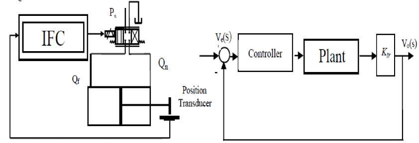
Fig.1 Schematic diagram of the cylinder
Fig.2 Block diagram representation of single-actuator system
The transfer function for the single-actuator system is
Vo(s)Ve(s)
K o
(TvS+1)(4 + Z s+1)s(4 + ~ s +1) tov ®v too too
where Ko = Ktr .Cv .Af , Vo is the output voltage according to the piston position, Ve is the error signal Kv voltage, Ko is the overall system gain and Ktr is the position transducer gain.
Table 1 Specifications of the system
Diameter of piston
Diameter of piston rod
Stroke
Load natural frequency
Load damping ratio
Total flow pressure coefficient
Valve flow gain, no load
Natural frequency of servo valve
Damping factor of servo valve
Supply pressure
House - delay time
112.7 mm
70.4mm
1000mm
19.6 rad/s
0.1
4.425x10⁻¹¹ (m3/s)/(N/m2)
2.613x10⁻³ m3/s/mA
688.7 rad/s.
0.3572
7 MPa
0.006 s
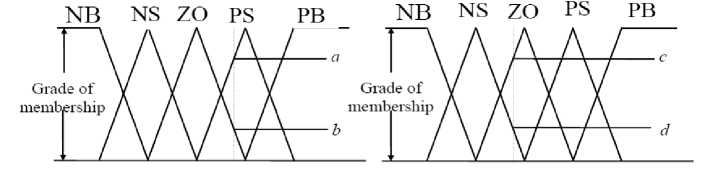
(a) Error
(b) Change in error
Fig.3 Triangular membership function
-
3.3. The Inference Process
-
3.4. Defuzzification
The basic operation of the inference process is to determine the values of the of the controller output based on the contributions of each rule in the rule base. One method of storing the rule base is the use of the Macvicar - Whelan control matrix [4] (Table 2). This matrix is designed so that if the desired output is realized with zero change in error, then the output remains constant. However, if the output is different from the desired response, then the rules produce an output signal based on human knowledge of the operating system. Each element of the matrix describes a rule of the form:
If e(t) is Ei and de(t) is dEj then f(t) is Ci,j , where e(t) and de(t) are the error and change in error, f(t) is the controller output, Ei and dEj are the applicable input function, and Cij is the output function.
Table 2 Macvicar - Whelan fuzzy rule matrix.
eft)
deft)
|
NB |
NS |
ZO |
PS |
PB |
|
|
NB |
NB |
NB |
NB |
NS |
ZO |
|
NS |
NB |
NB |
NS |
ZO |
PS |
|
ZO |
NB |
NS |
ZO |
PS |
PB |
|
PS |
NS |
ZO |
PS |
PB |
PB |
|
PB |
ZO |
PS |
PB |
PB |
PB |
Choosing triangular membership functions, for the input signals, ensures that a max. of four rules apply for the error shown in Fig. 3(a) and the change in error shown in Fig. 3(b). To determine the output values, a weighted average of the active rules is used as follow:
F ( t ) =
a • c • PS + a • d • ZO + b • c • ZO + b • d • NS
a • c + a • d + b • c + b • d
F(t) is the controller output, a and b represent the membership values for the error, c and d represent the membership values for the change in error, and the terms NS,ZO,PS are the peak values of the output membership functions. It should be noted that the denominator in (9) will be one when the triangular function are symmetric.
-
3.5. Fuzzy Controller Design Procedure
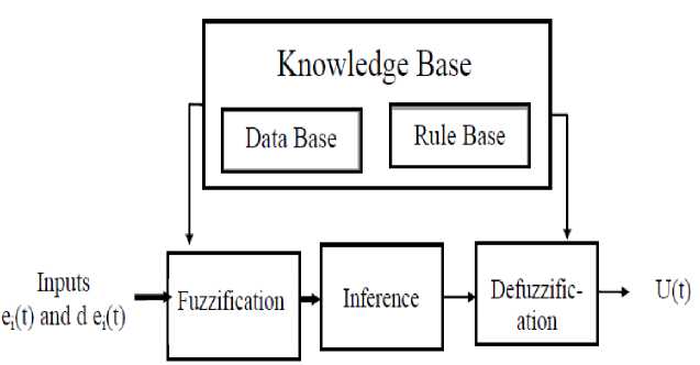
The block diagram of the structure of fuzzy control system is shown in the Fig. 4. The fuzzy logic controller designed include three important steps: Fuzzification, fuzzy reasoning and defuzzification. The error and the change in error will be fuzzified with the membership function. The used membership functions of error and change in error are triangles shaped, which is shown in Fig. 3.
The design procedure of the fuzzy controller is as follows:
-
• Choice of the state variables and the membership functions for the fine regulation, the larger the number of the fuzzy state valuables the more control rules will be. But the control rules will be more complex and difficult to design. To reduce the number of the control rules and to achieve good control performance are important for the fuzzy controller design.
-
• Determine the control rules as described in Table 2.
-
• Defuzzify the control signal through the defuzzification process to determine the control signal U.
-
4. Simulation results
Fig.4 Fuzzy logic controller
The simulation results to step response are shown in Figures 5 and 6 with PID and FLC are simulated under the same loading conditions. By comparing these two figures beside Fig. 7, it can be observed that the IFC has an excellent control performance than traditional PID, and it removes over shoots and oscillation.
Figures 8-9 show that the PID control is sensitive to the plant parameters variations (load damping ratio and frequency). In the other hand the FLC is insensitive to the parameter changing of the plant. Figures 10-11 show another advantage of FLC compared with PID control with positive step disturbance rejection. It is more faster and without oscillations. In Fig. 12 the response of the system under FLC policy offered robust response even with characterized by different delay times.
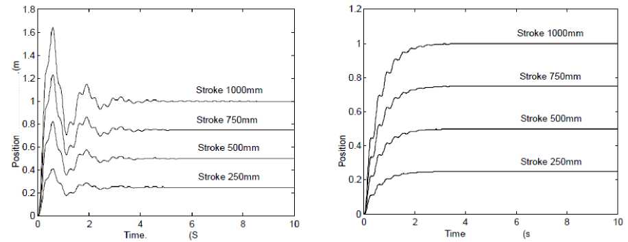
Fig. 5 System Step Response Based on PID Controller
Fig. 6 System Step Response Based on Fuzzy Logic Controller
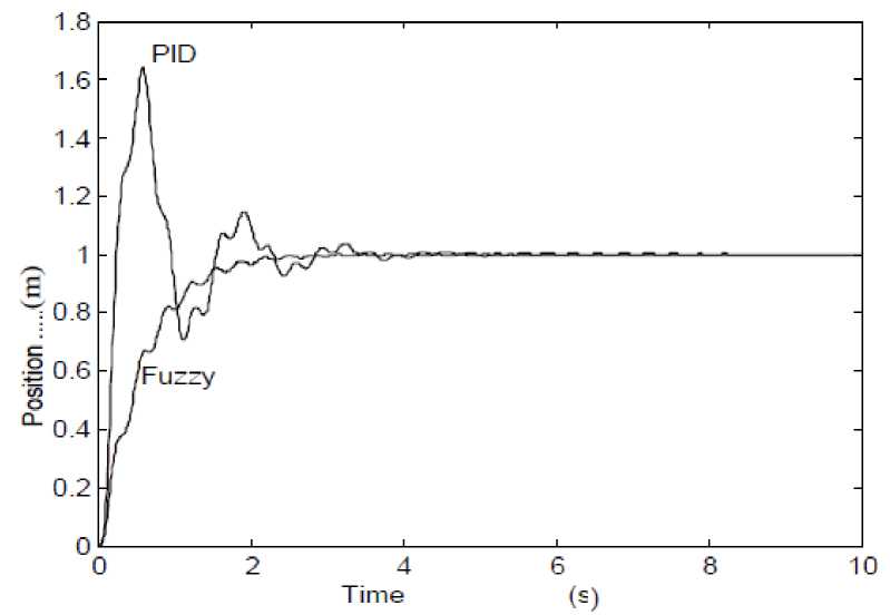
Fig. 7 System step response based on PID and Fuzzy Logic Controllers
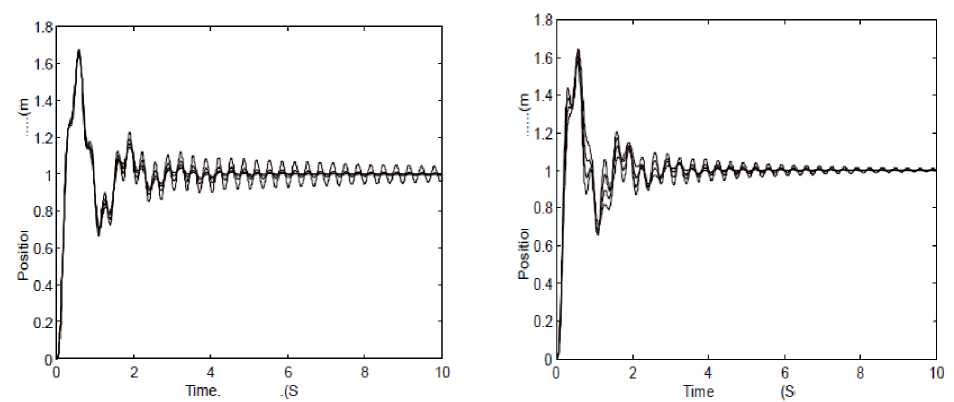
Fig. 8 System step response based on PID controller with ω o variations
Fig. 9 System step response based on PID controller with δ variations
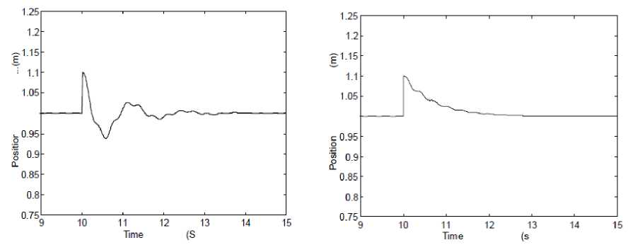
Fig. 10 System positive step disturbance response basd on PID controller
Fig. 11 System positive step disturbance response basd on Fuzzy logic Controller
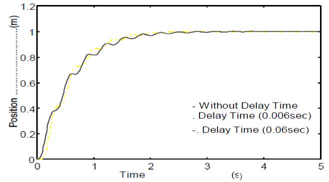
Fig. 12 System step response with and without delay time base on Fuzzy Logic Controller
-
5. Conclusion
The control problem of electro-hydraulic cylinder is studied in this paper. A self learning intelligent controller based on fuzzy logic and control knowledge has been given. It is shown that the intelligent fuzzy controller has a good learning effect and robust control performance.
The main advantage of the FLC:
-
• The control algorithm is simple and does not need a precise model.
-
• When the system working condition is altered, i.e., the damping ratio or the frequency is changed, the control algorithm is much more robust than that of the PID.
-
• The algorithm is easy to implement even on small microprocessor systems. The successful application of the FLC on the hydraulic power system is a breakthrough in this field. Extending this proposed FLC policy for MIMO servo systems is a very important and promising application.
References Self Learning Intelligent Controller of Electro hydraulic Actuator
- Ayman A. Aly, "Model Reference PID Control of an Electro-hydraulic Drive" I. J. Intelligent Systems and Applications (IJISA), 11, 24-32, 2012.
- Ayman A. Aly, “Intelligent fuzzy controller with road surfaces identifier for antilock brake system,” Int. J. Mechatronics and Automation (IJMA), Vol. 1, Nos. 3/4, pp 153-160, 2011.
- Zhao,T. and Virvalo,T., “Fuzzy State Controller and Its Application in Hydraulic Position Servo”, Fluid power, Page 417, (1993).
- Zhang, B., and Edmunds, J., “Self - Organizing Fuzzy Logic Controller”, IEEE Vol. 139, No.5 Sept. (1992).
- Ali Yousef and Ayman A. Aly, “Effect of Non-linearities in Fuzzy Approach for Control A Two –Area Interconnected Power System”, IEEE International Conference on Mechatronics and Automation (ICMA 2010) China, August 4-7, 2010.
- Purows, L., Ch.4,”Control of Fluid Power Analysis and Design”, Van Nostrand Reinhold Company, New York, (1987)
