Shortcomings of ultrasonic obstacle detection for vehicle driver assistance and profiling

Author: James I. Obuhuma, Henry O. Okoyo, Sylvester O. McOyowo
Journal: International Journal of Information Technology and Computer Science @ijitcs
Article in issue: 6 Vol. 11, 2019.
Free access
Obstacle detection is a challenging problem that has attracted much attention recently, especially in the context of research in self-driving car technologies. A number of obstacle detection technologies exist. Ultrasound is among the commonly used technologies due to its low cost compared to other technologies. This paper presents some findings on the research that has been carried out by the authors with regard to vehicle driver assistance and profiling. It discusses an experiment for detection of obstacles in a vehicle driver’s operational environment using ultrasound technology. Experiment results clearly depict the capabilities and limitations of ultrasound technology in detection of obstacles under motion and obstacles with varied surfaces. Ultrasound’s wavelength, beam width, directionality among others are put into consideration. Pros and cons of other technologies that could replace ultrasound, for instance RADAR and LIDAR technologies are also discussed. The study recommends sensor fusion where several types of sensor technologies are combined to complement one another. The study was a technical test of configurable technology that could guide future studies on obstacle detection intending to use infrared, sound, radio or laser technologies particularly when both the sensor and obstacle are in motion and when obstacles have differing unpredictable surface properties.
Obstacle Detection, Driver Profiling, Ultrasound, Ultrasonic Sensors, Bayesian Network, 2TBN, Sensor Fusion, Driver Assistance
Short address: https://sciup.org/15016364
IDR: 15016364 | DOI: 10.5815/ijitcs.2019.06.04
Text of the scientific article Shortcomings of ultrasonic obstacle detection for vehicle driver assistance and profiling
Published Online June 2019 in MECS
Vehicle drivers operate in complex environments that comprise of other vehicles, pedestrians, bicycles, motorcycles and barriers among other things. These environments are non-deterministic due to their dynamic nature. The behaviour of vehicle drivers is hence heavily influenced by actions of other road users in addition to their personal states, mechanical conditions of vehicles, states and structures of roads among other factors. A lot of research is being done towards assisting drivers in various ways to help improve on road safety. Two such recent studies were conducted by Obuhuma, Okoyo and McOyowo [1, 2], in a move to explore mechanisms for driver assistance and driver profiling.
The first study [1] presented a model for driver assistance by proposing a real-time advisory model based on nearness to mapped points of interest (POI) and/or overspeeding behaviour. The study was limited to speed-limited zones, intersections, bumps and black spots as test POIs [1]. The K-Nearest Neighbour (KNN) algorithm centered on the Spherical Law of Cosines was used to determine drivers approaching mapped POIs [1]. A text-to-speech Android app read text SMS alerts sent to drivers to avoid diversion of driver’s attention. The model [1] is kind of a Vehicular Ad-hoc Network (VANET) as a low cost Vehicle-to-Driver communication using GPS, GSM and GIS. The study was a technical test of configurable technology supporting elements of Intelligent Transportation Systems (ITS), whose implementation will influence on driving behaviour, hence improving on performance and road safety.
The second study [2] demonstrated the application of Dynamic Bayesian Networks (DBN) in the determination of driving styles with respect to acceleration, cornering and braking patterns. Test results showed that the 2-Time-slice Bayesian Network (2TBN) model is suitable for generation of driver profiles using only four GPS data parameters, namely, speed, altitude, direction and GPS signal strength against time [2]. The model classifies driver profiles into two sets of observations: driver behaviour and nature of operational environment.
The two studies [1, 2] were limited to the use of only GPS data as a way to offer cost effective, easy to implement and use solutions that could find many applications in vehicle driver recruiting firms, vehicle insurance companies and transport and road safety authorities among other sectors.
This paper presents an extensional study aimed at obstacle detection as a way to assist vehicle drivers and/or add an extra variable for driver profiling. The study explores the use of ultrasonic sensors for detection of obstacles in a driver’s environment. Study findings clearly brings out capabilities and limitations of ultrasonic obstacle detection technology with clear suggestions for appropriate technologies and techniques for obstacle detection. Sensor fusion is hence a major recommendation in some applications, especially where obstacles with differing physical properties is the norm.
The rest of the paper is organized as follows: section II presents some literature on ultrasound obstacle detection, section III outlines the research design and methodology used, section IV illustrates an experiment carried out with its findings, section V discusses experiment results as section VI concludes with recommendations.
II. Related Work
Real-time obstacle detection and avoidance has been brought out in studies ranging from as early as 1980’s [3-5] to most recent studies [6, 7]. A number of obstacle detection techniques exist. These could be compared across different key metrics including sensing range, resolution, directionality, response time, cost, size and environmental immunity [7]. Some of these techniques include ultrasonic, passive infrared, laser radar, impulse radar, frequency modulated-continuous wave (FMCW) radar, capacitive and video-based vision [7]. Ultrasonic and infrared sensors find many applications in mid-range distance measurements [8]. Ultrasonic sensors allow for detection of even small and hard to sense obstacles such as tree branches or cables at high frame rates, as well as see-through obstacles such as windows [9].
Ultrasonic sensors work by measuring the time of flight of sound energy of a short burst with the transmitter and receiver separated [7, 8]. The transmitter converts electrical signals into ultrasound while the receiver converts the reflected ultrasound into electrical signals. Fig. 1 outlines the concept of ultrasonic sensing for obstacle detection. When an electrical pulse of high voltage is applied to the ultrasonic transducer, it vibrates across a specific spectrum of frequencies generating a burst of sound waves. At whatever time the waves hit an obstacle and forms incidence, a reflection is created in form of an echo that generates an electric pulse. The echo patterns received by the sensor’s receiver are then compared with the patterns of sound waves to determine detected signal’s condition. The distance to an object is determined by measuring the time taken from the point a pulse is transmitted to the point the reflection is received [7, 8, 10].
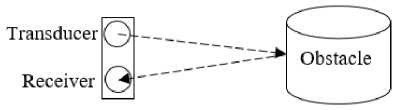
Fig.1. The Concept of Ultrasonic Sensing
Ultrasound technology has been used in a number of studies with varied outcomes. For instance, it has been applied in blind people assistance systems including [11-14]. In one of these studies, a self-contained portable electronic unit for blind people assistance was proposed by Bousbia-Salah et. al [11]. The system is composed of a microcontroller, an accelerometer, a foot switch, a speech synthesizer, a hexadecimal keypad, a mode switch, two ultrasonic sensors, two vibrators and a power switch [11]. The unit can assist blind people on walking route navigation by using spoken words to point out decisions to make [11]. Although the system has the capability to detect nearest obstacles, it cannot solve the blinds' ultimate problem of perceiving the environment. This is due to ultrasound reflections such that many objects can barely be detected, for instance, those with very small or soft surfaces [11]. In the same line but using the phase beamforming technique to process the output signal of microphones, the model by [14] was able to determine the direction from which the reflected signal is received, thereby locating the obstacle more precisely. It is however worth noting that there is no system yet that the visually impaired users are confident about its reliability, robustness, and overall performance. Most of the existing systems are in the best case, at the prototype stage. Hence, real time, long-term experiments with visually impaired people have not been performed [12].
Ultrasonic technology has also been applied in Unmanned Aerial Vehicles (UAVs). UAVs are particularly useful in applications where the operating site cannot be reached by ground operating vehicles or applications that require an aerial view of the whole scene [9]. Gageik, Benz and Montenegro [6], demonstrated a simple innovative solution for obstacle detection and collision avoidance for UAVs, optimized for and evaluated with quadrotors. Ultrasonic and infrared range finders were used as they are much cheaper though noisier than more expensive and reliable sensors such as laser scanners [6]. This was a sensor fusion model where two sensor technologies were used to complement one another, just like in the case of [8]. It clearly came out that sensor fusion could help mitigate limitations and capabilities of one sensor technology.
Other obstacle detection approaches used image processing, for instance [15-17]. In such cases, cameras are used for obstacle data collection as opposed to proximity sensors. For example, one of these studies by Zheng, Wang and Zhang [15] proposes an obstacle detection and measurement approach centered on machine vision. The technique detects an obstacle, retrieves the window that cover the obstacle and then uses digital image processing to get the detailed measurement of the object [15]. The success of such a technique heavily relies on the algorithm(s) behind image processing. The study was limited to detection of a 2 dimensional view of the obstacle, hence, further work needs to be done on the algorithm to achieve a 3 dimensional view [15]. Zheng, Wang and Zhang [15] concluded that, pattern recognition and neural network need to be introduced to help in the learning process.
This study explores the capabilities and limitations of ultrasonic sensor technology for obstacle detection in a real vehicle driver’s operational environment. Some of the targeted obstacles in such an environment include other vehicles, pedestrians, motorcycles, bicycles, barriers, among other objects.
III. Research Design and Method
The prototype is composed of a GPS receiver, an Arduino Uno microcontroller, an Ultrasonic proximity sensor, a 5V DC SPDT Power Relay and a GPS server. The circuit diagram is as outlined in Fig. 2 with the source code for the program controlling the Arduino Uno microcontroller following later in the discussion. In summary, the microcontroller periodically sends trigger signals to the proximity sensor on test vehicle for determination of obstacles within range. It then interprets sensor echo signals to generate a high or low output signal that acts as input to the GPS receiver via a power relay. This value complement GPS data that is subsequently transmitted to the GPS server via GPRS.
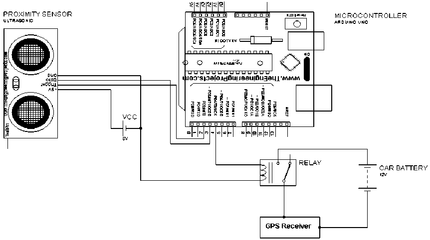
Fig.2. Circuit Design for the Obstacle Data Collection Unit
Microcontroller (Arduino Uno)
Arduino is an open-source computer hardware and software company, project and user community that designs and manufactures kits for building digital devices and interactive objects that can sense and control the physical world [18]. An Arduino board consists of an Atmel 8-bit AVR microcontroller with complementary components that facilitate programming and interfacing with other circuits through a specially designed printed circuit board (PCB) [18, 19]. The Arduino integrated development environment (IDE) is a Java-based cross-platform application [18, 19] that includes a code editor with features such as syntax highlighting, brace matching, and automatic indentation. It is also capable of compiling and uploading programs to the board with a single click [18]. To make an executable cyclic Arduino program, a definition of only two functions is required: setup and loop functions as will be seen in the microcontroller program.
The Arduino board can be supplied with direct current (DC) power from an AC-to-DC adapter or battery or draw power from a USB connection [20]. The microcontroller is programmed using the Arduino programming language, which is based on C or C++ [18, 21, 22]. The Arduino IDE comes with a software library called “Wiring” from the original Wiring project, which makes many common input/output operations much easier [18]. The main features of an Arduino Uno board are: ATmega328P microcontroller, 7 – 12 input voltage, 14 digital input/output pins (6 of which are PWM outputs), 6 analog inputs, 32k flash memory, 16Mhz quartz crystal clock speed, USB connection, Power jack, ICSP header and the Reset button.
Table 1. HC-SR04 Technical Specifications
|
Description |
Rating |
|
Working Voltage |
DC 5V |
|
Working Current |
15Ma |
|
Working Frequency |
40Hz |
|
Maximum Range |
400cm |
|
Minimum Range |
2cm |
|
Measuring Angle |
15 degree |
|
Trigger Input Signal |
10 μ S TTL pulse |
|
Echo Output Signal |
Input TTL lever signal and the range in proportion |
|
Dimension |
45*20*15mm |
Proximity Sensor (HC-SR04)
The HC-SR04 proximity sensor is an obstacle detection sensor based on ultrasound technology. It is a low cost sensor that provides 2cm to 400cm of non-conduct measurement functionality with a ranging accuracy that can reach up to 3mm. The module includes an ultrasonic transmitter, a receiver and a control circuit. It has 4 pins: a
5 volts pin for power, a trigger pin for trigger signal, an echo pin to receive the reflected signal and a ground pin. Table 1 outlines the technical specifications for the HC-SR04 ultrasonic sensor used in this study. This is as specified in the manufacturer’s product datasheet.
Power Relay (5V DC SPDT)
This is a 5V power relay module that can be controlled directly by a wide range of microcontrollers such as Arduino, AVR, PIC, ARM and MSP430. The relay is suitable for numerous applications that include domestic appliances, office machines, audio equipment, automobiles etc. The 5V DC SPDT power relay has 5 pins as shown in Fig. 3. These are the COM pin, Normally Connected (NC) to COM pin, Normally Open (NO) to COM pin, two 5 volts COIL pins. The NC and NO pins enable it to act as a power switch for driving high voltage devices. The two COIL pins are supplied with 5 volts in either direction, creating a magnetic effect on the COIL that facilitate switching between NO and NC pins through attraction and release as shown in Fig. 3. The COM to NO or COM to NC connects to appliances or circuitries that support high voltages. In this case, they connect 12 volts power from a power source to the GPS receiver. This is used to denote presence or absence of an obstacle.
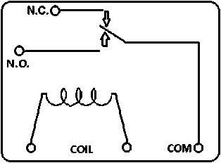
Fig.3. Power Relay Internal Layout
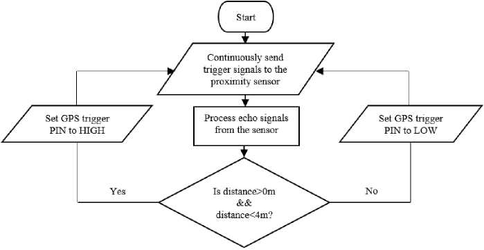
Fig.4. Microcontroller Communication with the Proximity Sensor
-
1 #define trigpin 2
-
2 ^define echopin 3
-
3 ^define gpstrigpin 4
-
5 void setup() {
Serial.begin(9600); pinMode(trigpin, OUTPUT); pinMode(echopin, INPUT); pinMode(gpstrigpin, OUTPUT); 10 } 11
-
12 void loop{) {
int distance, duration; digitalWrite(trigpin, HIGH); delayMicroseconds(1000);
digitalWrite(trigpin, LOW); duration = pulseln(echopin, HIGH); distance = (duration/2)/29.1;
if(distance>0 & distance<1000){ digitalWrite(gpstrigpin, HIGH) 25 } else{ digitalWrite(gpstrigpin, LOW);
28 }
29 }
Fig.5. Microcontroller Program Code
Microcontroller Program
The flowchart in Fig. 4 outlines the flow of events as the microcontroller sends trigger messages to the proximity sensor during the process of obstacle detection. An obstacle is detected if it falls within a 4-meter range where by the GPS trigger PIN is set to HIGH. As a result, the power relay circuit is completed, causing GPS data send to the server to include a value that indicates detection of an obstacle. Otherwise the GPS trigger PIN is set LOW, opening the power relay circuit, an indicator that no obstacle is detected. The process occurs as a continuous loop as long as the vehicle engine is on.
Fig. 5 shows the source code for the program that was used to control the Arduino Uno microcontroller. Line 23 of the source code provides room for adjustment of obstacle sensing distances as a way of calibration of the model. If an obstacle is detected within the specified distance range in centimeters, then line 24 is executed. This would set the GPS trigger pin, defined as gpstrigpin to HIGH. On the other hand, if no obstacle is detected within the range, line 27 executes, setting the GPS trigger pin to LOW.
GPS Receiver
The study was established on an on-board unit that uses GPS technology to collect data from GPS satellites then transmit the data to a GPS server for processing using GPRS technology. The choice of the devices was informed by the required parameters that include vehicle speed, altitude, direction and a timestamp.
GPS Server
The data transmitted by a GPS receiver ends up on a GPS server that has a receiver application running continuously with a specific open port listening to incoming connections. A GPS server by Obuhuma and Moturi [23] could serve the purpose after minor enhancements to incorporate the obstacle parameter. The server [23] was developed based on socket programming technology with an SQL based database. Communication between the GPS receiver and the GPS server application is achieved through GPRS technology over the GSM network.
Driver Assistance and Profiling
This study extends the 2TBN model described in [2] by adding one extra variable i.e. obstacle to speed, altitude, direction and GPS signal strength variables. Fig. 6 shows the improved 2TBN model with five parameters. The model represents a Bayesian Network with three copies of time-slices where each time-slice is also a Bayesian Network. The probabilities for the three time-slices is a summarized by equation (1) to (3).
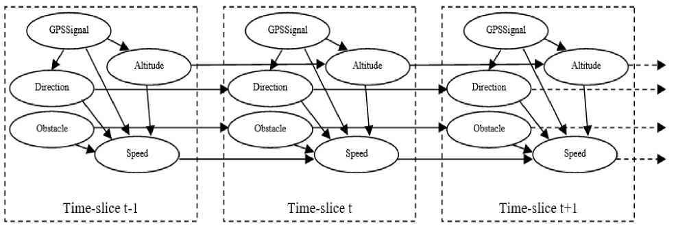
Fig.6. Extended 2TBN Model for Driver Profiling
P(Prof ilet-1) = P(Altitudet-1 | GPSSigiralt-1). P(Directiont-1 | GPSSigiralt-1) . P(Speedt-1 | Altitude t-1, Dir ectiont-1, Obstacle t-1 , GPSSiguolt-A)
This means that as time progresses, a new time-slice is generated. In which case, assuming good GPS signal strength, the value of each of the three key GPS data variables in addition to the obstacle variable is affected by the immediate previous value in the prior time-slice. There can be as many time-slices as the number of times the change in time is recorded. Driver behaviour profiles could thus be computed as described in [2] with a consideration of the additional obstacle variable.
IV. Experiment And Results
The GPS trigger pin was for experimental purposes connected to an LED rather than a GPS receiver, such that, if the LED turns on, then an obstacle is detected, otherwise, if it goes off, then no obstacle is detected. A serial monitor for the Arduino IDE was also used to display actual distances in centimeters for any obstacle detected.
The proximity sensor was mounted on the front end of a Toyota Carina saloon car’s bonnet at a height of 70 centimeters from the ground, such that it was taking a clear front view of the car. The microcontroller circuitry with LED was positioned inside the car with a long cable connecting to the proximity sensor. A laptop with Arduino IDE was connected to the microcontroller via a USB interface. The serial monitor program was up and running to display readings at intervals of 100 microseconds as defined in line 21 of the microcontroller program.
A road test was carried out to determine the performance and reliability of obstacle detection. Table 2 summarises experiment results under different maximum detection distances.
It is evident from the results presented in Table 2 that the LED was ON continuously for distances greater than 2 meters. This was the case regardless of whether there was an obstacle within the vicinity or not. This was an indicator that the sensor was continuously detecting some obstacle within its surrounding area. For distances less than or equal to 2 meters, all seemed to work fine i.e. the LED turned on whenever there was an obstacle otherwise it went off. This was however not consistent for actual road test scenarios. For instance, at certain points during actual road tests, it could delay a bit to turn on despite an obstacle being within the 2-meter range. For some instances, it could fail to turn on completely even with an obstacle within a detectable range. It was observed that obstacle detection worked better at low driving speeds.
Table 2. Experiment Results
|
Detection Distance (Meters) |
Obstacle Presence |
LED Status |
|||
|
Yes |
No |
On |
Off |
||
|
1 |
3.1 – 4.0 |
x |
x |
||
|
2 |
3.1 – 4.0 |
x |
x |
||
|
3 |
2.1 – 3.0 |
x |
x |
||
|
4 |
2.1 – 3.0 |
x |
x |
||
|
5 |
1.1 – 2.0 |
x |
x |
||
|
6 |
1.1 – 2.0 |
x |
x |
||
|
7 |
0 – 1.0 |
x |
x |
||
|
8 |
0 – 1.0 |
x |
x |
||
More experiments were carried out with the sensor adjusted to different heights. The second experiment was done with the sensor lowered to a height of 50 centimeters from the ground. Unfortunately, the new position worsened the outcome since proper obstacle sensing distance reduced from 2 meters to about 1.5 meters. The third experiment was done with the sensor positioned at a height of 90 centimeters from the ground, which was higher than the first experiment’s position. Proper obstacle sensing distance increased from 2 meters to about 2.5 meters. Proper sensing distance kept on increasing for further experiments that involved raising the sensor position higher and higher. This was however limited to a maximum height of 200 centimeters from the ground during which proper sensing distance was within a 4-meter range. Unfortunately, this worked fine only for static obstacles with wide detectable surfaces. Obstacles under motion could only be accurately detected within 2-meter ranges with some fewer detection failures. In some instances, the LED failed to turn on completely even with an obstacle within its range. The accuracy rate seemed to be higher under slow driving speeds i.e. speeds less than 10 km/h.
Unfortunately, the sensor could not be raised any further than 200 centimeters from the ground. This was due to the fact that a driver’s environment is composed of obstacles with different detectable surface areas and heights and can be in different positions and angles with respect to the sensor’s position. Thus, the higher the sensor’s position, the lower the probability of detecting obstacles with smaller heights.
V. Discussion of Results
-
A. Discussion Based on Findings
The velocity of ultrasonic wave travel in air is affected by environmental parameters such as temperature, humidity and appearance of ambient noise [8]. Nevertheless, it came out clearly that ultrasonic sensors have limitations due to their wide beam widths and sensitivity to mirror-like surfaces that enhance reflection. Hence, it was established that at the sensor height of 70 cm, the large beam width was the cause of continuous obstacle detection for distances greater than 2 meters. The sensor was perceiving the ground as an obstacle since it sends trigger signals at a very wide angle. This is as outlined in Fig. 7 where the ground surface reflects waves at distances greater than 2 meters. The ultrasonic sensor used, send signals at an angle of 150, translating to a beam width of 300. Similarly, the waves were reflected at a round angle of 300 as shown in Fig. 7. A decrease in sensor position height for the second experiment, resulted in decrease in ground detection distance. On the other hand, an increase in sensor position heights for other experiments, resulted in an increase in ground detection distances.
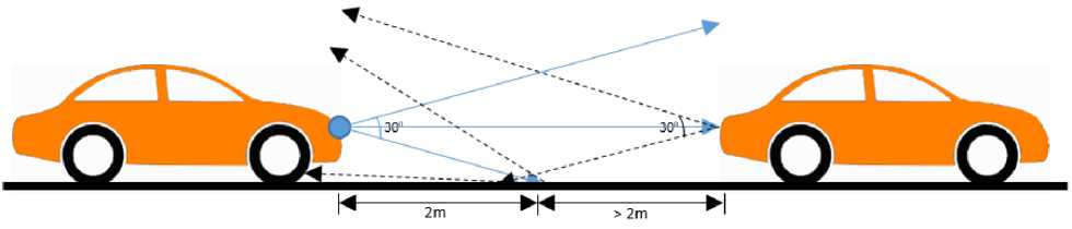
Fig.7. Operational Concept of Ultrasonic waves
The mirror-like property of ultrasonic waves as depicted in Fig. 7, enables only reflecting objects that are almost normal to the sensor acoustic axis to be accurately detected. It is worth noting that for an object to be detected, the sound waves must be incident on the object for it to reflect diffused incident energy. Hence, the type and nature of surface that the sound waves hit has an effect on the formulation of incidence and the strength of the reflected wave. During actual road tests, the types of objects detected varied widely i.e. some had wide surfaces, smooth surfaces, uneven surfaces among others. The variation heavily contributed to obstacle detection delays and inconsistencies even for distances within 2 meters. Unfortunately, this is the norm of the nature of obstacles within operating environments of vehicle drivers.
In cases of objects in motion, establishment of incidence may fail to occur due to changing distances and positions. On the same note, reflected waves may also fail to reach back to the sensor’s receiver. Definitely, these factors may have additionally contributed to obstacle detection delays and inconsistencies.
In an actual driving scenario, using a GPS receiver alone for data collection has a great potential in determining a driver’s driving style with probabilities determining the operational environment. The ultrasonic obstacle sensor operating at less than 2 meters’ detection distance and under slow speeds will be too limiting for driver assistance and profiling unless if used to only detect extremely risky behaviour relating to driving at very close ranges to other vehicles. Such close driving distances is the norm in city scenarios, especially during traffic jams. Hence, may beat the logic of profiling drivers based on risky behaviour as the results may not be a true picture of a driver’s behaviour.
-
B. Proposed Solution Based on Findings
To achieve better and reliable results in obstacle detection, the following two considerations could be put in place:
-
1. Alternative Technologies
-
2. Sensor Fusion
Alternative obstacle detection technologies could be used. For instance, the Radio Detection and Ranging (RADAR) and the laser-based Light Imaging Detection and Ranging (LIDAR). However, they both come with pros and cons. Both technologies use the concept of sending signals that bounce back upon hitting an obstacle’s surface. The distance to the object is calculated based on the time taken for each pulse to bounce back. RADAR uses radio waves while laser-based LIDAR uses laser light waves. Radio waves travel further than sound waves and are undetectable to human sensory organs, thus best suited for long-range obstacle detections. Both radio and light waves have relatively same speeds, though radio waves have less absorption compared to light waves. This makes radio waves propagate well in relatively longer distances. Laser-based LIDAR is the preference for automakers as it creates a 3D image of the obstacle making it possible to determine the exact size of an object. However, it is affected by darkness and cloudy weather. In addition, the technology is more expensive than RADAR. The development of a RADAR based obstacle detection and warning system was pushed ahead by Mercedes Benz in the 90’s [24]. Presently, automakers like Google, Uber, Tesla and Toyota use either or both RADAR and laser-based LIDAR technology in addition to cameras, ultrasonic and infrared technologies. Airplanes, military vehicles, battleships and marine equipment heavily rely on RADAR technology.
The FMCW is an example of a RADAR technology that uses electromagnetic waves transmitted by a front-end antenna system with the reflected signal used to determine target distance and speed. The waves may be at microwave frequencies or higher. The technology best suits environments with poor visibility, penetrates mud and sprays and also allows for adjustment of beam widths to suite particular applications [7]. On the other hand, the laser-based LIDAR technology sends focused laser light beams that are suited for long range, high directionality and fast response time applications [7]. Hence, this may solve the problem of detections of the ground as an obstacle, as was the case for ultrasonic sensors. Unfortunately, laser lights are affected by poor environmental visibility hence cannot penetrate mud or sprays. Both RADAR and laser-based LIDAR technologies however come at a high cost compared to ultrasonic and infrared technologies.
Sensor fusion entails combining two or more technologies such that they complement one another. For instance, if cost is a major issue, ultrasonic sensors could be combined with infrared sensors to offer the following advantages:
-
i) Ultrasonic sensors could complement infrared sensors that fail under poor lighting conditions such as smoke or fog and cannot detect transparent objects.
-
ii) On the other hand, infrared sensors could complement ultrasonic sensors that face challenges in detecting sound absorbing surfaces or soft surfaces.
A major advantage for such a sensor fusion lies in the fact that both technologies are cheap as compared to other high cost technologies like RADAR and laser-based LIDAR. The main disadvantage is that both technologies are limited to mid-range detection. Thus, cannot detect obstacles that are too far.
In cases where cost is not a limiting factor, then RADAR and laser-based LIDAR could also be fused to complement one another. If necessary, radio, laser, ultrasonic and infrared technologies could all be fused for reliability and accuracy in obstacle detection. As early mentioned, modern day automakers working on self-driving cars are already embracing this kind of sensor fusion in addition to the use of sophisticated cameras and data and image processing algorithms.
A proper and well-thought sensor fusion will mitigate challenges in obstacle detection particularly when both the sensor and obstacle are in motion and when obstacles have differing unpredictable surface properties.
VI. Conclusion and Recommendations
Ultrasound is one of the commonly used technologies in obstacle detection. This is due to its low cost compared to other technologies. The technology however comes with a number of shortcomings that limit its applications in certain areas. This study sought to apply ultrasonic technology in obstacle detection in a real road scenario. The results of the experiments that were conducted indicate clearly some of the limitations of ultrasound for obstacle detection in a real road situation. These limitations revolve around detection under motion, detectable surfaces, wavelength, beam width, directionality, among others.
Besides the mentioned aspects, it has to be taken into consideration that ultrasound and infrared are complementary technologies. Infrared sensors, like all optical sensors, fail under poor lighting conditions such as smoke or fog and cannot detect transparent obstacles. This is contrary to ultrasonic sensors, which do not pose such drawbacks. However, ultrasonic sensors have a challenge in detecting sound absorbing or soft surfaces like clothes. They are thus not reliable in the detection of objects like people, which is no challenge for infrared sensors.
Sensor fusion where multiple types of sensors are combined to complement one another is a major recommendation just like for the case of other studies like [3, 7]. For high reliability and accuracy in obstacle detection, other technologies like laser-based LIDAR and RADAR could also be considered for fusion. However, this comes at an extra cost. The use of Ad hoc networks for instance VANETs is also attracting attention in this current world that is inclined towards talking cars and driverless car technologies.
References Shortcomings of ultrasonic obstacle detection for vehicle driver assistance and profiling
- J. I. Obuhuma, H. O. Okoyo, and S. O. Mcoyowo, “Real-time Driver Advisory Model: Intelligent Transportation Systems,” in IST-Africa 2018 Conference Proceedings, IEEE Xplore, 2018.
- J. I. Obuhuma, H. O. Okoyo, and S. O. Mcoyowo, “Driver Behaviour Profiling Using Dynamic Bayesian Network,” MECSJ. Mod. Educ. Comput. Sci., vol. 7, pp. 50–59, 2018.
- J. Borenstein and Y. Koren, “Real-time obstacle avoidance for fast mobile robots,” IEEE Trans. Syst. Man. Cybern., vol. 19, no. 5, pp. 1179–1187, Sep. 1989.
- S. Walter, “The sonar ring: Obstacle detection for a mobile robot,” in Proceedings. 1987 IEEE International Conference on Robotics and Automation, vol. 4, pp. 1574–1579.
- J. Borenstein and Y. Koren, “Obstacle avoidance with ultrasonic sensors,” IEEE J. Robot. Autom., vol. 4, no. 2, pp. 213–218, Apr. 1988.
- N. Gageik, P. Benz, and S. Montenegro, “Obstacle Detection and Collision Avoidance for a UAV With Complementary Low-Cost Sensors,” IEEE Access, vol. 3, pp. 599–609, 2015.
- M. Upton and M. Upton, “Techniques for Distance Measurement,” vol. 104, no. 1995, pp. 2023–2029, 2018.
- B. Mustapha, A. Zayegh, and R. K. Begg, “Ultrasonic and Infrared Sensors Performance in a Wireless Obstacle Detection System,” in 2013 1st International Conference on Artificial Intelligence, Modelling and Simulation, 2013, pp. 487–492.
- D. Holz, M. Nieuwenhuisen, … D. D.-I. A. P., and U. 2013, “Towards multimodal omnidirectional obstacle detection for autonomous unmanned aerial vehicles,” academia.edu.
- L. Scalise et al., “Experimental Investigation of Electromagnetic Obstacle Detection for Visually Impaired Users: A Comparison With Ultrasonic Sensing,” IEEE Trans. Instrum. Meas., vol. 61, no. 11, pp. 3047–3057, Nov. 2012.
- M. Bousbia-Salah, A. Redjati, M. Fezari, and M. Bettayeb, “An Ultrasonic Navigation System for Blind People,” in 2007 IEEE International Conference on Signal Processing and Communications, 2007, pp. 1003–1006.
- D. Dakopoulos and N. G. Bourbakis, “Wearable Obstacle Avoidance Electronic Travel Aids for Blind: A Survey,” IEEE Trans. Syst. Man, Cybern. Part C (Applications Rev., vol. 40, no. 1, pp. 25–35, Jan. 2010.
- W. C. S. S. Simoes and V. F. de Lucena, “Blind user wearable audio assistance for indoor navigation based on visual markers and ultrasonic obstacle detection,” in 2016 IEEE International Conference on Consumer Electronics (ICCE), 2016, pp. 60–63.
- M. R. Strakowski, B. B. Kosmowski, R. Kowalik, and P. Wierzba, “An ultrasonic obstacle detector based on phase beamforming principles,” IEEE Sens. J., vol. 6, no. 1, pp. 179–186, Feb. 2006.
- X. Zheng, S. Wang, and Y. Zhang, “The Obstacle Detection and Measurement Based on Machine Vision,” MECSJ. Intell. Syst. Appl., vol. 2, pp. 17–24, 2010.
- V. R. Shah, S. V Maru, and R. H. Jhaveri, “An Obstacle Detection Scheme for Vehicles in an Intelligent Transportation System,” MECSJ. Comput. Netw. Inf. Secur., vol. 10, pp. 23–28, 2016.
- Y. Singh and L. Kaur, “Obstacle Detection Techniques in Outdoor Envi-ronment: Process, Study and Analysis,” MECSJ. Image, Graph. Signal Process., vol. 5, pp. 35–53, 2017.
- M. Bansode, S. Jadhav, and A. Kashyap, “Voice Recognition and Voice Navigation for Blind using GPS,” Int. J. Innov., 2015.
- J. Sarik and I. Kymissis, “Lab kits using the Arduino prototyping platform,” 2010 IEEE Front. Educ., 2010.
- S. Tarapiah, S. Atalla, and B. Alsayid, “Smart on-board transportation management system Geo-Casting featured,” Comput. Appl., 2014.
- C. Galeriu, “An Arduino-controlled photogate,” Phys. Teach., 2013.
- M. Ulaganathan and C. Saravanan, “Cost-effective Perturb and Observe MPPT Method using Arduino Microcontroller for a Standalone Photo Voltaic System,” Int. J., 2014.
- J. Obuhuma and C. Moturi, “Use of GPS with road mapping for traffic analysis,” Int. J. Sci. Technol., 2012.
- W. Ulke, R. Adomat, K. Butscher, and W. Lauer, “Radar Based Automotive Obstacle Detection System,” 1994.
