Side grounded conductors dipped in a substrate of a microstrip line, as a tool of line characteristics control

Author: Sagiyeva I. Ye., Gazizov T.R.
Journal: Сибирский аэрокосмический журнал @vestnik-sibsau
Section: Авиационная и ракетно-космическая техника
Article in issue: 2 т.19, 2018.
Free access
Electrical design of on-board radio-electronic equipment is an important stage in spacecraft design. High charac- teristics of printed circuit boards (PCBs) are essential for miniature units that have reliability, speed, stability of elec- trophysical parameters, electromagnetic compatibility. In order to do that, new design and technological solutions are necessary, in particular transmission lines with stable characteristics of per-unit-length delay (τ) and wave impedance (Z). One of the main lines, realized on a PCB is a microstrip line (MSL). In multi-layer PCBs it is often used with poly- gons. However, their influence on the stability of characteristics is investigated insufficiently. The purpose of the work is to investigate the dependence of τ and Z of MSL on the distance between the side grounded conductors as they are dipped in a substrate. In the TALGAT software we built a geometric model of the line cross-section and calculated (using the method of moments) the matrices (3*3) of per-unit-length coefficients of electrostatic induction taking into account the dielectric as well as ignoring it. We calculated the values for the change of distance between side conductors (s), dipped in a sub- strate, for different values of the height of the side conductors (h1). We revealed that for large values of s (unlike small ones), approaching of the side conductors to the air-substrate boundary does not increase but it decreases the value of τ. When s = 0.38 mm, the change of the value of h1 in the whole range almost doesn't change the values of τ and, therefore zero sensitivity of τ to changes of h1 is possible. Thus we can obtain the required Z value in the range from 48 to 59 Ohms by changing the value of h1. These results are obtained for particular values of the parameters of the line. However it is easy to obtain similar dependencies for other values of parameters. The results can be used to design transmission lines with stable delay un- der control of the impedance value.
Printed circuit board, microstrip line, per-unit-length delay, impedance, polygons, zero sensitivity
Short address: https://sciup.org/148321842
IDR: 148321842 | UDC: 621.372.8.01 | DOI: 10.31772/2587-6066-2018-19-2-303-307
Боковые заземленные проводники, углубленные в подложку микрополосковой линии, как средство контроля её характеристик
Электрическое проектирование бортовой радиоэлектронной аппаратуры является важным этапом созда- ния космических аппаратов. Высокие характеристики печатных плат (ПП) важны для миниатюрных узлов, обладающих надежностью, быстродействием, стабильностью электрофизических параметров, электромаг- нитной совместимостью. Для этого необходимы новые конструкторско-технологические решения, в частно- сти, линии передачи со стабильными характеристиками погонной задержки (τ) и волнового сопротивления (Z). Одной из основных линий, реализуемых на ПП, является микрополосковая линия (МПЛ). В многослойных ПП она часто используется с полигонами. Однако их влияние на стабильность характеристик мало исследовано. Цель статьи - исследовать зависимости τ и Z МПЛ от расстояния между боковыми заземленными про- водниками при их углублении в подложку. В системе TALGAT построена геометрическая модель поперечного сечения линии и методом моментов вы- числены матрицы (порядка 3*3) погонных коэффициентов электростатической индукции с учетом диэлек- трика и без него. Выполнены вычисления при изменении расстояния между боковыми проводниками (s), углуб- ленными в подложку, для разных значений высоты боковых проводников (h1). Выявлено, что при больших зна- чениях s, в отличие от малых, приближение боковых проводников к границе «воздух-подложка» не увеличива- ет, а уменьшает значения τ. При s = 0,38 мм изменение значения h1 во всем диапазоне почти не меняет значе- ния τ, а значит, возможна нулевая чувствительность τ к изменению h1. При этом изменением значения h1 можно получить требуемое значение Z в диапазоне от 48 до 59 Ом. Данные результаты получены для конкретных значений параметров линии. Однако легко получить анало- гичные зависимости при других значениях параметров. Результаты работы могут быть использованы для проектирования линий передачи со стабильным значением задержки при контроле волнового сопротивления.
Text of the scientific article Side grounded conductors dipped in a substrate of a microstrip line, as a tool of line characteristics control
Introduction. Electrical design of on-board radioelectronic equipment is an important stage in the spacecraft design [1]. High characteristics of printed circuit boards (PCBs) are important for miniature units [2; 3] that have reliability [4], speed, stability of electrophysical parameters [5], electromagnetic compatibility [6]. In order to do that, new design and technological solutions are necessary, in particular transmission lines with stable characteristics of per-unit-length delay (τ) and wave impedance ( Z ). Thus the research of these characteristics is relevant [7–10].
One of the main lines, realized on PCB is MSL. Various modifications of MSL are the most interesting, for example, suspended and inverted strip lines which make it possible to obtain zero sensitivity of the per-unit-length delay and wave impedance to the change in the thickness of dielectric layers [11]. A similar pattern was found in MSL coated with a grounded conductor, shielded MSL [12] and MSL with side grounded conductors placed above [13]. There is a detailed analysis of modifications and variances in such a line and its varieties. Multilayer PCBs use a variety of MSL, for example, MSL with polygons on different layers that allows to obtain a stable value of the per-unit-length delay [14]. Meanwhile, it is useful to study the characteristics of MSL with side conductors grounded only on one layer located near the boundary of two environments.
The purpose of the work is to investigate the dependence of τ and Z of MSL on the distance between the side grounded conductors as they are dipped in a substrate.
To achieve the objective, we investigated the structure of MSL with side conductors dipped in the substrate (fig. 1). We chose the following cross-sectional parameters (they are close to typical): the width of the signal conductor is w = 0.3 mm, the thickness of the signal and side grounded conductors is t = 18 μm, the width of the side conductors is w 1 = 1 mm, the thickness of the dielectric substrate is h = 1 mm, the relative permittivity of the substrate is ε r = 4.5.
Line modeling. In the TALGAT [15] software we built the geometric model of the line cross-section and calculated (using the method of moments) the matrices (3*3) of per-unit-length coefficients of electrostatic induction taking into account the dielectric as well as ignoring it.
From the matrices we took the values (hereinafter C and С 0 ) of the diagonal element corresponding to the signal conductor and calculated the values of τ and Z ( v 0 is the speed of light in vacuum):
τ = ( C/C 0 )0.5/ v 0 , Z = 1/( v 0 ( CC 0 )0.5).
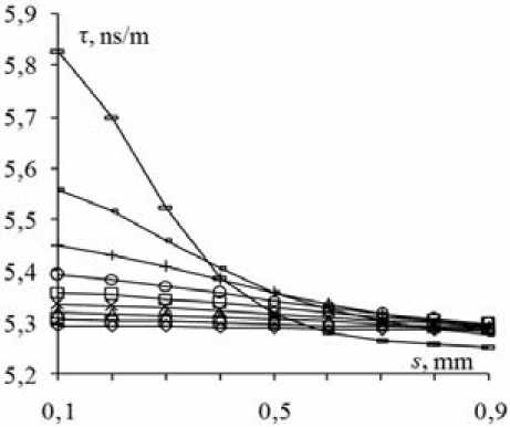
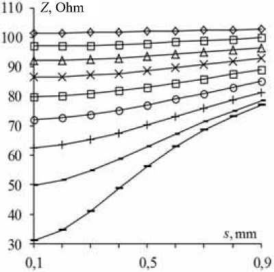
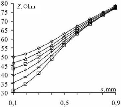
We calculated the values for change of distance between the side conductors s , dipped in a substrate, for the height of the side conductors h 1 = 0.1–0.9 mm (fig. 2). Fig. 2 shows that when s increases, the value of τ decreases smoothly, and Z increases. At small values of h 1, the changes of τ and Z are small, but the growth of h 1 leads to an increase in the value of τ and a decrease in the value of Z , and at small values of s the changes of τ and Z are more significant.
Approaching of the side conductors to the air– substrate boundary has a special effect on the characteristics being studied. Therefore, we performed simulation with a smaller step at the air-substrate boundary: at h 1 = 0.8; 0.82; 0.84; 0.86; 0.88; 0.9 mm (fig. 3). The analysis of fig. 3 shows a similar behavior of dependencies, but it reveals its specificity as well. It is expressed in the amplification of the influence of the side conductors when they approach the air-substrate boundary for small values of s . When s = 0.1 mm, the value of τ increases from 5.56 to 5.82 ns/m. We noticed that for large values of s , approaching of the side conductors to the airsubstrate boundary does not increase but it decreases the values of τ. When s = 0.6 mm this decrease is maximal and is from 5.33 ns/m to 5.29 ns/m. When s = 0.38 mm, the change of the value of h 1 in the whole range almost doesn’t change the values of τ and, therefore zero sensitivity of τ to changes of h 1 is possible. Thus we can obtain the required Z value in the range from 48 to 59 Ohms by changing the value of h 1.
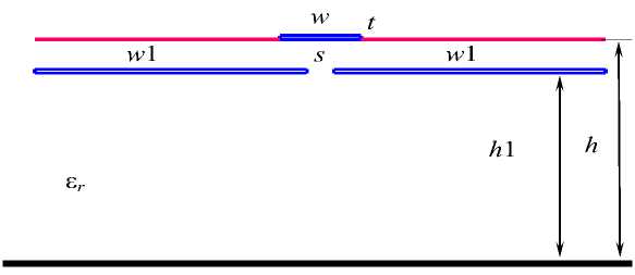
Fig. 1. Cross-section of MSL with side grounded conductors, dipped in a substrate
Рис. 1. Поперечное сечение МПЛ с боковыми заземленными проводниками, углубленными в подложку
a
Z , Ohm
60 ■ s,mm
b
Fig. 2. Dependences of τ (a) and Z (b) on s at h 1 = 0.1 (◊); 0.2 (□); 0.3 (A); 0.4 (x); 0.5 (□); 0.6 (o); 0.7 (+); 0.8 (-); 0.9(-) mm
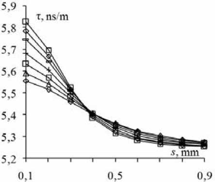
Рис. 2. Зависимости т (а) и Z (б) от s при h 1 = 0,1 (◊); 0,2 (□); 0,3 (A); 0,4 (x); 0,5 (□); 0,6 (o); 0,7 (+); 0,8 (-); 0,9(-) мм
a b
Fig. 3. Dependences of (a) and Z (b) on s at h 1 = 0.8 (◊); 0.82 (A); 0.84 (□); 0.86 (+); 0.88 (-); 0.9 (□) mm
Рис. 3. Зависимости т (а) и Z (б) от s при h 1 = 0,8 (◊); 0,82 (A); 0,84 (□); 0,86 (+); 0,88 (-); 0,9 (□) мм
Conclusion. We modeled MSL with side grounded conductors dipped in a substrate. We calculated the dependence of the per-unit-length delay and the wave impedance on the distance between the grounded conductors when the depth changes. We found out that zero sensitivity of per-unit-length delay to depth changes is possible while obtaining the required wave impedance. These results are obtained for the particular values of line parameters.
However it is easy to obtain similar dependencies for other values of parameters. The results can be used to design transmission lines with stable characteristics.
Acknowledgments. This research was carried out with the financial support of the Ministry of Education and Science of the Russian Federation RFMEFI57417X0172.
References Side grounded conductors dipped in a substrate of a microstrip line, as a tool of line characteristics control
- Исследование воздействия электромагнитного излучения на космический аппарат с негерметичным приборным отсеком/С. Г. Кочура //Технологии электромагнитной совместимости. 2017. № 3(62). С. 3-10.
- Газизов Т. Р., Заболоцкий А. М., Орлов П. Е. Влияние длины и количества витков на задержку микрополосковой линии//Инфокоммуникационные технологии. 2014. Т. 13, № 4. С. 93-96.
- Распространение импульса в меандровой линии с неоднородным диэлектрическим заполнением без искажений его формы перекрестными наводками/Р. С. Суровцев //Доклады ТУСУРа. 2014. № 4(34). С. 34-38.
- Orlov P., Gazizov T., Zabolotsky A. Comparative electromagnetic and quasi-static simulations of a short-pulse propagation along microstrip meander delay lines with design constraints//Journal of ELECTRICAL ENGINEERING. 2016. Vol. 67, no. 5. Р. 387-389. DOI: 10.1515/jee-2016-0056
- Газизов Р. Р., Заболоцкий А. М., Газизов Т. Т. Исследование максимума напряжения сверхкороткого импульса в микрополосковой меандровой линии при изменении ее геометрических параметров//Технологии электромагнитной совместимости. 2016. № 3(58). С. 11-17.
