Simulation of the operation of induction machines at frequencies other than 50 Hz

Author: Jeroslav M. Živanić, Nenad A. Marković, Slobodan N. Bjelić
Journal: International Journal of Information Technology and Computer Science @ijitcs
Article in issue: 7 Vol. 10, 2018.
Free access
In the paper is proposed an induction machine model that corresponds to operating conditions at the change of frequency. The applicability of simulation method for the analysis of its operation at the frequencies other than 50 Hz was examined. The operation of the induction machine which control parameter is the frequency of controlled current was particularly analyzed. The evaluation of the proposed model was performed using the adapted subprogram in the psbdrive MATLAB Simulink package. For the verification of the results, the method of verified simulation was used, as a part of the method which was derived from the artificial intelligence algorithm. It has been confirmed that by controlling the frequencies and current of the induction machine, the ability to work in overloads can be maintained and this type of control has certain advantages in the frequency regulation of the drive with variable loads.
Induction machine, Frequency control, Mechanical characteristic, Sliding
Short address: https://sciup.org/15016276
IDR: 15016276 | DOI: 10.5815/ijitcs.2018.07.02
Text of the scientific article Simulation of the operation of induction machines at frequencies other than 50 Hz
Published Online July 2018 in MECS
Although the principles remained the same, much has changed from the occurrence of the first frequency converter, which contained thyristors, to the appearance of today's micro-processor-driven converter [1]. Due to the increasing presence of automatics in the industry, there is a constant need for automatic control and the continuous increase in production speed and better methods for improving the efficiency of the drive have been constantly developed.
Induction machines are very important product today and are projected to operate with constant speed and over the past years the control of their speed has been optimized.
Most of static frequency converters now used in the industry for regulation or control of the three-phase motors are made based on two principles:
-
• Converters without intermediate circuits (as direct converters),
-
• Converters with variable or constant intermediate circuits.
Improving the technology of inverters in power electronics, microprocessors and integrated circuits has a major impact on the digitalization of drives in which higher speeds are used [2]. The advantages of digital control are reflected in the stability of the control parameters and easier management of measurement quantities. Old analog drives that were adjusted by potentiometers or passive components caused a problem when operation conditions of the induction machine were changed [3].
Frequency control has a large application in the operation of induction machines. Modern frequency converters can provide frequency regulation in larger scope of speeds at different operating frequencies. IGBT and MOSFET transistors are used for the regulation because they have good control characteristics (appropriate scope of feed, conductance, and interruption frequency). The standards related to regulation and control of induction machine that must be followed are IEC 60034-1 and IEC 60947-4-1 [4].
The paper is organized as follows: The review of papers dealing with the frequency control of induction machines is presented in Section 2. Section 3 represents the operating conditions of the three-phase induction machines as well as the role of frequency regulators. In Section 4 are given equations of state from which the characteristics of induction machine are obtained, and which can easily be implemented in the software package MATLB Simulink. The simulation results of frequency control of induction machine are given in the Section 5.
In Section 6 are given simulation results and discussion of proposed induction machine model. Section 7 gives some concluding remarks.
-
II. R elated W orks
Dealing with the problem of the operation of induction machines at different frequencies is not a new phenomenon. Many studies concerning this topic have been conducted and large number of papers have dealt with this issue [1,5,6].
In the last century, Sluis was dealing with the problem of the frequency in the induction machines [6], who suggested that this problem should be addressed by using computers, because he concluded that faster and simpler solutions were obtained (although we must admit that in that period computer technology was not nearly as developed as today).
According to Sluis and Fehmel [5,7], it is possible to design the electromotor drives in which frequency regulation takes place in a very wide range in a similar way as in DC machines with voltage, but generally the speed setting problem is much more complex. How does the speed of these induction motors change?
If the power frequency is changed, the synchronous speed also changes (the characteristic moment speed leftright changes). The synchronous speed is obtained in the intersection of characteristic and abscissa. The synchronous speed is equal to the quotient of power frequency and the number of poles pairs, as concluded by Markovic, Bjelic, Mahfouz, Mohammed et.al. [8,9]. They argue that if only the frequency of the sources that supply the induction machine changes, the magnetic flux that significantly impacts the external characteristic of the machine also changes. This means that when rotation speed of the induction machine changes due to the change of the frequency, the value of the voltage on the connections of the machine must also change, if it is to achieve the given mechanical characteristics.
-
III. PWM, F requency R egulators and O perating C onditions of T hree - phase I nduction M achines
In modern technology and topology the principles of inverters control is determined by semiconducting elements of a new type (IGBT, GTO, IGCT, SGCT), and also different types of PWM, for example PWM relay, programmed PWM with selective damping of higher harmonics, PWM with more levels, PWM combined with amplitude-impulsive modulation, etc.
The aim to obtain currents and voltages for supplying the induction machines with smaller content of harmonics at the output of the inverter, based on the opinion of the author of this paper, is determined by a few issues that manufacturers of the inverters must resolve [5,8]. For example, the inverters with 3-level and commutation in “star” (with fixed zero point or fixed star connection (Neutral Point Clamped-NPC)), or with 4-level voltage. The next step for the improvement of the shape of the inverter output voltage is realization of the multi level inverter.
In [8] are formulated the requirements that must be met to reduce the impact of the harmonics and implement a quality way to control induction motors that respond to the output frequency.
It is best, through the electromagnetic compatibility of an autonomously powered inverter with an induction motor and the GDS (General Distributive System), to provide appropriate electrical energy quality parameters according to IEC and EN standard. Then, the optimization of the components consisting of the series-connected semiconducting elements of the new generation is performed. Finally, it is also necessary to improve the diagnostics of converter devices through preventive control of electric power circuits:
-
• Improve the functions of microprocessor controllers,
-
• Improve tests for examination of the elements of the plant and converters at their output,
-
• Stimulate the application of new construction materials, optoelectronics, and
-
• Improve the cooling mode of semiconductor components.
As mentioned previously, IGBT transistors are used because they have goof control properties and their outputs collector-emitter are bipolar (have low parasitic inductances).
Unlike the MOSFET-a, the imput IGBT is gate and is activated by voltage not by current. IGBT inverter and its control circuit are placed at "Power Width Modulation-PWM" [8,9,10]. PWM is a method for generation of three-phase voltage with given frequency and the overall voltage of the intermediate circuit U ® 2 x Umains is switched off or on by electronic components. The pulse with between the switching off and on is variable and the adjustment of voltage is possible [11].
There are three main ways for PWM inverters control: sine controlled PWM, synchronous operation of PWM and asynchronous operation of PWM.
Three branches of PWM inverters can have two different positions (on/off). Three circuit breakers generate eight possible breaker combinations, that is, eight discrete voltage vectors at the output of the inverter on at the stator winding of connected induction motor, Fig. 1.
Sine controlled PWM refers to the application of sinusoidal reference voltage Us for each inverter output. The length of sinusoidal voltage period corresponds to desired fundamental frequency of the output voltage. Output voltage is a function of the time of switching on and off and time ratio can be change to generate the desired voltage. Therefore, the amplitudes of voltage positive and negative pulses always correspond to the half of the intermediate circuit voltage.
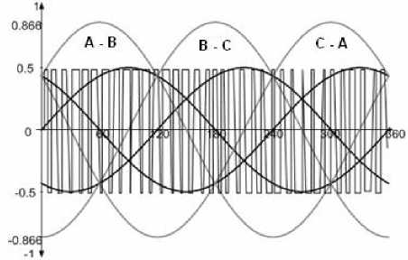
Fig.1. Switching form of the phase with voltage.
Induction machine torque T ≈ Φ ⋅ Ir is proportional to induction machine air gap between the rotor and stator. The steep of the mechanical characteristic depends on the square of the flux M ≡ Φ 2 . If we manage to maintain Φ as a constant value, the mechanical characteristic of the induction machine could reradiate. This could provide a constant steep of mechanical characteristic, so the synchronous speed could correspond to power frequency. The question is how to get this power? The motor is powered by a special drive converter that will provide a three-phase voltage system of continuously variable amplitude and variable frequency.
In most applications of induction motors, the energy is pumped from the city network and supplied to the AC-DC rectifier and then to the three-phase transistor converter/inverter. The three-phase transistor converter has the task of transforming the power and energy of the DC current into the power and energy of the alternating current with a continuously variable frequency and voltage.
The set range of regulated speeds of induction machine is achieved by selecting the operating frequencies, that is, the frequency of power source. Lower frequencies in relation to the frequency of the electric installation and induction machine are not desirable because the operating conditions of the induction machine and converter are deteriorating. The increase of the frequency creates additional losses in magnetic circuit of the induction machine and deteriorates its power characteristics [12].
The question that arises is how to determine optimal number of poles in induction machines and frequency of power supply for arbitrary value of the given speed. To optimize the induction motor torque, the flux of air gap is Φ ≈ V / f . It should remain constant, which means that when the frequency f is changed the voltage V also needs to be changed [13,14].
For difficult start-ups and optimal value of brake torque, the additional (starting) voltage V 0 is required. When induction motor is loaded and in the scope of low frequencies f < 50 Hz, the voltage is lost on the stator winding active resistance (in small induction motors). Thus, in order to maintain the flux of induction machine, the voltage drop must be compensated. The simplest methods for voltage drop compensation are:
-
A. Increasing the Input Voltage in the Lower Speeds Scope by Control in Open Coupling
This type of control has limitations at hard measurable disturbances when load variations are high (e.g. at a drive with operating variations of coil resistance up to 25% between warm and cold state). The increase of input voltages can lead to different results. If there is no load, this can lead to flux saturation or when the induction machine is loaded to decreased flux. In the case of saturation, the higher reactive current can flow, which leads to the heating of induction motor. In the case of load, the induction machine develops low torque due to weak flux and the delay occurs.
-
B. Regulation of Output Voltage by Applying the Active Component of the Converter Output Current for the Increase of the Torque (Known as IZ = R Compensation or Start-up Compensation)
In the past it was difficult to adjust frequency regulator for induction machine since the compensating functions “initial voltage”, “start” and “slip compensation” were difficult to understand. Advanced frequency regulators automatically control the compensation parameters based on rated frequency of induction motor, voltage and current, but the compensation is nevertheless adjusted manually. The compensation parameters (dependant and independent of load) provide optimal magnetization and maximum torque during the start-up, as well as at low speeds of the induction motor. The output voltage gains additional voltage that efficiently exceeds the effects of ohm induction motor resistance at low frequencies.
-
C. Load-dependent Voltage Additions
Start and slip compensation is determined by measuring the active current.
-
D. Load-independent Addition
-
3.1. S lip C ompensation
Slip of induction motors is dependent on the load and is up to 5% of nominal speed. For two-pole induction motor with the speed n = 3000 min-1 slip can be up to 150 min-1. The slip would be approximately 50% of required speed if the frequency converter had controlled induction motor at the speed of n = 300 min-1 = 10 %.
Start-up voltage guarantees the optimal brake moment in the scope of low speeds. Induction motor smaller than recommended size, can require additional, manual voltage addition that would provide optimal magnetizing in the scope of low speeds. If a greater number of induction motors is controlled with one frequency converter (parallel operation), load-dependent compensation should not be used. With last-generation converters, this compensation is set automatically with frequency converter (for standard applications).
If the frequency converter controls induction motor at 5% of nominal speed, the induction motor will not react to the load. The load dependency is not desirable, and frequency regulator is able to fully compensate the slip by efficient measurement of active current in the output stages of frequency converter. Regulator compensates the slip by increasing the frequency and this is called active slip compensation.
-
IV. I mpact of C urrent L imitation on T orque C haracteristics of I nduction M achine -M otor
When frequency regulator generates much higher currents than rated current of induction motor that are not needed for normal operation, they can damage induction motor and feeding components in the frequency regulator. It is, therefore, necessary that the frequency regulator indirectly limits the current of induction motor by reducing the output voltage and its frequencies. The limitation of current is variable and ensures that the current of the induction motor is not always higher than the rated value.
Since the frequency converter controls the induction motor speed independently from the load, different values of limitation within the rated operating scope of the induction motor can be adjusted.
Electric model of induction motor in the static operation mode with linear magnetizing curve and without the influence of iron losses is given on Fig. 2.a.
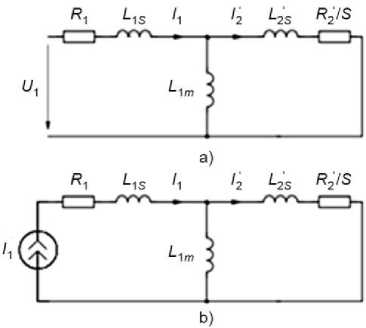
Fig.2. a) Equivalent scheme of the induction motor, b) Equivalent scheme of the induction motor fed by power generator.
In the modeling, the system of equations written for the equivalent scheme according to Kirchhoff’s law determined by the selection of the coordinate system is used.
When rotating the system into x - y the system of Cartesian coordinates, equations of state from which the induction machine characteristics are obtained have the form [15,16,17]:
i1 xR1 - ® 0 V1 y = u1 x i1 yR1 + ® 0 V1 x = 0
i 2 xR 2 - s® 0 V 2 y = 0
i 2 yR 2 + s ® 0 V 21 x = 0
where s - is slip and is s = ( m 0 - m 20 ) /® 0 , ® 0 ,® 20 — is spin velocity of magnetic stator field and speed of rotation of induction machine rotor, V 1 y ,V 1 x,V 2 y ,V 2 x — are projections of fluxes of stator and rotor on coordinate axes.
The values of fluxes are determined by following expressions:
V 1 y = L 1 i 1 y + L 1 M i 2 y
V 1 x = L 1 i 1 x + L 1 M i 2 x
V 2 y = L 2 i 2 y + L 1 M i 2 y
V 2 x = L2 i2 x + L1 Mi1 x where Li ,L2 - is inductance of the stator phases and reduced inductance of the rotor.
In this case, the inductance of the stator phases and reduced inductance of the rotor is:
L 1 = L 1 s + L 1 M
L 2 = L 2 s + L 1 M
Inductances L 1 s , L' 2 s , L 1 M are represented on Fig. 2.a and 2.b.
Electromagnetic torque in rotating coordinate x - y system is:
T = ^ Z P ( v 1 x i 1 y - V 1 y i 1 x ) . (6)
where Z p - is the number of poles pairs of the induction motor.
The system of relations (1)-(6) is easy to implements in blocks offered by software package MATLAB Simulink [18].
Model designed for software package MATLAB Simulink allows simulation with induction motor parameters according to given slip and mechanical characteristics of the torque at the different rotation speeds [19,20].
One possibility is to consider induction motor characteristics at different given rotation speeds, for example, analysis of induction motor operation at the frequency control with the regulated stator voltage.
The control legitimacy at the frequency control is achieved by neglecting the impact of active stator resistance, which makes errors in the equations that describe dependence between the frequencies and voltages on the stator. To the increase the quality of regulation, the IR and IZ compensation is used.
Figure 3 represents the induction motor characteristics during the control through the voltage and current characteristics.
Diagram on Fig. 3 shows that in voltage characteristic the regulation scope of the rotation speed of induction motor depends on the compensation mode, and that in voltage characteristic at any compensation mode the regulation scope is limited.
p _ 3 '' 2 R2 ( 1 - 5 )
PM = "^I1 -------
s
= M ^ 20 . Zp
Electromagnetic torque of the induction motor:
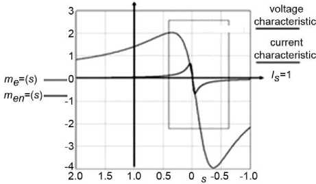
Fig.3. Characteristics of induction motor when controlled through voltage and current characteristic.
-
V. S tate A nalysis and S imulation of I nduction M achine
Vector control allows the induction motor to be controlled when there is no known dependence between the torque on the shaft (axis) of the rotor and the speed of rotation. According to this mode of control, a wide range of frequency regulation can be obtained for values of nominal torques or during short-term overloads up to 150-200% of the nominal torque.
It should be noted that the vector method is good if technical data on the induction motor are known and if tests on its operation are performed.
The vector method is realized using complex calculations performed by computer technology and uses data on the values of input currents, frequencies and voltages. Inverter uses bipolar transistors with isolated blockage (BTIZ or IGBT) and PWM modulation and minimum harmonic coefficient (less than 4%).
The control of the stator current regulation differs from the control by the stator voltage. If the model psbdrive MATLAB Simulink is appied in accordance with the relations (1)-(6), the analysis of drive static characteristics indicates that the stator current must be stabilized. In reality, this is done by the strong current back coupling. Instead of back coupling for static analysis and simulation of the induction motor operation, it is sufficient to use power generator, scheme on Fig. 2.b. In modeling the operation and regulation of induction machine operation in MATLAB Simulink, the back couplings are accomplished by the algebraic loops. The current generator on the scheme for simulation in fact is current regulator.
Current generator simulates the frequency current control that maintains the rotor flux constant in the proces of frequency regulation. From the scheme on Fig. 2.b follow the formulas for:
Electromagnetic power of the induction motor:
'
3 Rэ M = 3 ZJ^ 2 -2-.
2 p 2 sω 0
Reduced rotor current to stator:
'
' jω0L1M
I 2 = 11 7------'-------'■ jto 0 L 2 + R 2 / 5
By replacing equation (9) in equation (8) the equations for torques through stator current are obtained:
M = KI12----------.(10)
5 / 5kr + 5kr / 5
where the value of the critical slip is:
5KR = — .(11)
where т2 = L2 /R2 - is a time constant of rotor electric circuit, and coefficient K is K = —Z„
2 p
2 L 1 M
`
L 2
The parameters of stator circuit are excluded from the equation (10), which means that electromagnetic torque at the frequency control with the stabilization of current, Fig. 2.b, does not depend on stator winding parameters and the compensation of active resistance impact is not needed.
This is the first important advantage of frequencycurrent control. If we take into account that:
s/sKR = т2 (®0 - ®20 ).
the expression of electromagnetic torque in the equation (10) is reduced to:
M = KKIт2 (TO0 - to20 ).
where KI = . ^1= .
V1+ т 2 ( to 0 - ю 20 ) 2
In frequency control is necessary to determine the dependence of the current I1 on the slip value («0 - to20). In the operating scope, the coefficient KI has a constant value because at the constant slip the torque will also be a constant value. The regulation scope in current control without stator current correction is not difficult to determine, if we start from the condition that the circular frequency too is a minimal possible value at which the critical (moving) torque is achieved.
From the equation (11) follows:
_ 1 _ to 0 - to KR
toKR = to 0 - T 2 .
Minimal circular frequency ω 0 min is determined at critical to KR = 0. And from equation (15) follows:
to 0 min = T 2 . (16)
-
VI. R esults and D iscussion
The performed analytical considerations show the functional possibilities of the model with different frequencies. If it is compared with the results in the given references, the following observations can be emphasized:
-
• It follows from the given references that today PWMs that have a typical structure with current or voltage inverters are used and that it is determined by the values of current and voltage.
-
• The problem of the electromagnetic compatibility of the converter and induction motor is solved by choosing the structure of the controlling converter with different modulation modes-PWM, which
virtually produces sinusoidal shapes of output currents and output voltages.
-
• There are a number of methods for the realization of frequency converters used for the control of induction motors and synchronous motors and are mainly produced by world-wide high-ranking companies. Comparison of frequency converters shows that some of them are more reliable in operation but have a very expensive.
-
• In the Republic of Serbia, great attention is paid to the design and production of domestic frequency converter, but it is uncertain that it will be able to withstand the competition of world companies for quality, reliability and price.
-
• Attempts in some companies in the Republic of Serbia (M elektronik, Belgrade) show that converters of good parameters which enable reliable operation, good quality can be produced, but for the time being, it is not possible to withstand the competition regarding the technical and exploitation parameters of similar devices produced by Japanese and European manufacturers.
The performed analytical considerations show functional possibilities of the model with different frequencies.
Relations (7)-(11) allow the realization of parts of the scheme for the simulation of electric and mechanical characteristics of the induction motor at current control in program package MATLAB Simulink.
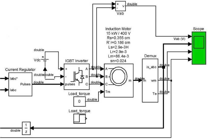
Fig.4. Simulation of induction motor operation at frequency regulation and current control by the current regulator in adapted part of the package psbdrive MATLAB Simulink.
For the analysis of frequency control characteristic as in the case of voltage regulation or compensation of stator current Iz = r the adapted part of the package psbdrive and scheme for the induction motor Z p = 2 “Sever-Subotica” [21], has been proposed, Fig. 4 where frequency converter of stator voltage (current) (IGBT Inverter), block for current linear regulation (Current regulator), dc voltage source (Vdc), induction motor of 15 kW and Scopy measuring results are implemented.
Tests related to parameter changes in Block parameters Asynchronous Machine have shown that:
-
• The induction motor fed from the converter with a three-phase voltage system of variable amplitude
and frequency should be designed in such a way that the dispersion reactance is as small as possible to achieve high overload.
-
• Induction motors fed from the converter require a different design, because there is no need to reduce the starting current, or rather, they do not have a quantity called the starting current (they never start up after supplying with nominal quantity voltage).
Table 1 indicates the rated values of the induction motor parameters which are important for the usage of frequency regulator (Current regulator) [21], while in Table 2 are given the basic values of parameters of the equivalent scheme from Fig. 4.
Table 1. Rated Values of the Induction Machine ZK 160 l-4 Obtained from the Catalogue [21]
|
Mechanical protection: IP 54 |
V 1 = 400 V , 50 Hz |
|||||||||||
|
Type of the induction motor |
P n kW |
nn min-1 |
η % |
cos ^ „ |
I n A |
M n Nm |
p* = I1- I n |
M 1 M n |
s n |
v |
J kgm2 |
Mass kg |
|
Induction motor ZK160 L-4 ns = 1500 |
15 |
1440 |
88.0 |
0.82 |
30 |
99.5 |
6.2 |
3.0 |
0.024 |
2.89 |
0.073 |
118 |
Table 2. Basic Values of the Parameters of the Equivalent Scheme ZK 160 L-4
|
Mechanical protection: IP 54 |
Parameters of equivalent scheme V 1 = 400 V , 50 Hz |
||||||
|
Electrical parameters |
R 1 Ω |
R ' 2 Ω |
L is H |
' L ir H |
R m Ω |
L m H |
sn |
|
Induction motor ZK 160L-4 ns = 1500 |
0.355 |
0.186 |
2.9e-3 |
2.9e-3 |
1.47 |
86.4e-3 |
0.024 |
Figure 5 represents diagrams of voltages, currents, torques and speeds, obtained at constant stator current 30 A on the model of the induction machine in the package psbdrive MATLAB Simulink.
When the characteristics of load are determined, there are four different set of data of the induction motor and methods for determination of the frequency regulator power size.
Method 1 . Frequency regulator can be determined quickly and accurately based on the current Im , which induction motor draws from the installation. If the induction motor is not completely loaded, its current can be measured on the similar system at full function.
According to technical data for the induction motor Pm ≈15 kW, 3×400 V and In = 30 A, the regulator is selected so that it has maximum continuous output current greater than or equal to 30 A for constant or square characteristics of the torque.
Method 2 . Frequency regulator can be selected based on apparent power Sm of the induction motor and apparent power of the frequency converter.
Induction motor of 15 kW and 3×400 V draws 14.73 A and apparent power S m = 3 • U • I .
According to documentation, frequency regulator is selected so that it has maximum continuous output greater than or equal to 10.2 kVA at constant or square characteristic of the torque.
Method 3. Frequency regulator can also be selected in accordance with the power Pm produced by the induction motor. However, cos φ and coefficient of utilization η depend on the load and the method is not accurate.
Example: Induction motor of 15 kW with coefficient of utilization n = 0 . 8 and cos ^ = 0 . 82 respectively, draws a power of S m = P m / n cos = 15 / ( 0 . 88 x 0 . 82 ) = 20 , 787 kVA.
Frequency regulator is selected according to technical data so that it has maximum continuous output greater than or equal to 21 kVA at constant or square characteristic of the torque.
Method 4 . For practical reason, rated value of the power of the most of frequency converters should be compatible with standard powers of the series of the induction motor. If the frequent regulators are selected based on this criterion, this may lead to inaccurate dimensioning of the converter, especially if induction motor is operating in full load.
Advantages of MATLAB Simulink are a large number of possible simulations, shapes and characteristic values of obtained wave diagrams verify the proposed method for analysis of the induction motor operation at the frequencies other than 50 Hz.
Completed MATLAB Simulink programs quite accurately simulate the frequency changes but personalized development of both models and programs has special advantages such as a detailed insight into all components of the model and program and the introduction of various changes that could otherwise not be included in the available software packages.
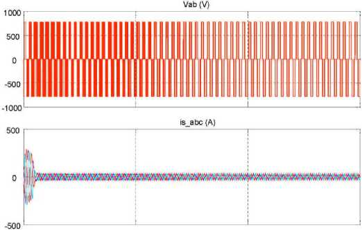
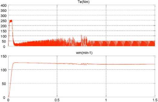
Fig.5. A set of characteristic of induction motor model in psbdrive MATLAB Simulink at selected current value of 30A.
-
VII. C onclusion
The design of the induction machine with good characteristics designed for operation and feeding through the frequency converter can include the optimal value of the voltage and feeding currents. This value depends on the type of frequency converter, type of the induction machine and limitations that are defined by IEC standards for the frequency converters and induction machines.
The model of the induction motor assembled in the part of the package psbdrive MATLAB Simulink has enabled testing of possibilities for frequency drive regulations in the case of frequency control and voltage control as well as in the case of frequency control with simultaneous current control. Since there are only two discrete states at the output, the continuity of the voltage and frequency is performed by means of PWM modulation.
The simulation results confirm that the frequencycurrent control can preserve a good operation of the induction machine in overload, and thus the advantage in relation to the drive regulation at the frequency control along with voltage control.
References Simulation of the operation of induction machines at frequencies other than 50 Hz
- L.W. Match, J.D. Morgan, “Electromagnetic and Electromechanical Machines”, 3rd Edition, Harper&Row Publishers, New York, 1986.
- N. Mohan, T.M. Undeland, W.P. Robbins, “Power Electronics: Converters, Applications, and Design”, John Wiley & Sons. Inc., Section 8.4.1., NewYork, 1995.
- J. Arrillaga, C.P. Arnold, B.J. Harker, “Computer Modeling of Electrical Power Systems”, New York: John Wiley & Sons, Inc., 1986.
- Standards: IEC 60034-1, IEC 60947-4.
- L. Van der Sluis, W.R. Rutgers, C.G.A. Koreman, “A physical arc model for the simulation of current zero behaviour of high-voltage circuit breakers”, IEEE Transactions on Power Delivery, Vol. 7, Issue 2, Apr. 1992, pp. 1016–1022, DOI: 10.1109/61.127112.
- L. Van der Sluis, “Transients in Power Systems”, John Wiley & Sons Ltd, 2001.
- G. Fehmel, M. Flachmann, Elektriche Machinen, 9 Auflage Vohel Bucheverlah, ISBN 3-8023-0495-0, 1992.
- N. Marković, S. Bjelić, J. Živanić, U. Jakšić, “Simulation of the Impact of Higher Harmonics on the Transient Process of Induction Machine Fed From PWM Inverters”, Technical Gazette, Vol. 24, No. 1, Preliminary communication, February 2017, pp. 265–271, DOI Number: 10.17559/TV-20150502231618.
- A.A. Mahfouz, M.K. Mohammed, F.A. Salem, “Modeling, Simulation and Dynamics Analysis Issues of Electric Motor, for Mechatronics Applications, Using Different Approaches and Verification by MATLAB/Simulink”, International Journal of Intelligent Systems and Applications, IJISA 2013, Vol. 5, No. 5, April 2013, pp. 39–57, DOI: 10.5815/ijisa.
- N. Marković, S. Bjelić, J. Živanić, V. Milićević, Z. Milićević, “Model of Transient Process Where Three-Phase Transducer Feeds Induction Motor Equivalented as a Variable Active-Inductive Load”, Mathematical Problems in Engineering, Vol. 2016, Article ID 6740261, Research Article, 2016, http://dx.doi.org/10.1155/2016/6740261.
- B. Rashidi, “FPGA Implementation of Digital Controller for Simple and Maximum Boost Control of Three Phase Z-Source Inverter”, International Journal of Information Technology and Computer Science, IJITCS2013, Vol. 5, No. 4, pp. 85–95, DOI: 10.5815/ijitcs.
- E.G. Andreeva, D.V. Šamec, “МКЕ анализ стационарных магнитных полей с помощью программного пакета АНСYС”: Učeb. Posobie. Omsk”, Izdvo OmGTU, 2002, pp. 92.
- E.F. Fuchs, M. Poloujadof, G.W. Neal, “Starting performance of saturable three-phase induction motors”, IEEE Transactions on Energy Conversion, Vol. EC-3, No. 3, September 1988, pp. 624–635.
- B. Jovanović, S. Bjelić, N. Marković, “Transient Processes on the Elements of Underground Installations”, International Journal of Information Technology and Computer Science, IJITCS2017, Vol. 9, No. 9, pp. 1–10, DOI: 10.5815/ijitcs.
- N. Marković, S. Bjelić, U. Jakšić, J. Živanić, “Scheme of device for voltage asymmetry correction”, Innovation and development, Bor, Serbia, No. 2, 2011, pp. 77–86.
- S. Bjelić, N. Marković, U. Jakšić, “The simplified procedure for calculation of Influence of thermal losses on decrease of technical endurance of electric equipment”, 3rd Regional Conference, Industrial Energy and Environmental Protection in the countries of South East Europe, Serbia, IEEP ’11, Kopaonik, MK Mountain Resort, June 21-25, 2011, pp. 28.
- L.L. Grigsby, “The Electric Power Engineering Hand book”, Chapter 10 Power System Transients, 10.6 Transient Voltage Response of Coils and Windings, CRC Press LLC, 2001.
- MATLAB SIMULINK Sim Power System, Copyright 1984-2002 The Math Works, Version 6.5.0,180913a, June 2, 2000.
- S. Bjelić, Z. Bogićević, “Computer Simulation of Theoretical Model of Electromagnetic Transient Processes in Power Transformers”, International Journal of Information Technology and Computer Science, IJITCS2013, Vol. 6, No. 1, pp. 1–12, DOI: 10.5815/ijitcs.
- N. Marković, S. Bjelić, J. Živanić, U. Jakšić, “Numerical simulation and analytical model of electrical arc impedance in the transient processes”, Elektronika, Energetika, Elektrotechnika, Przegląd Elektrotechniczny, 2013-2a2013, pp. 113–117.
- www.sever.co.rs, Low Voltage three-phase Motors Prospects.
