Smart Parking System with Image Processing Facility

Author: M.O. Reza, M.F. Ismail, A.A. Rokoni, M.A.R. Sarkar
Journal: International Journal of Intelligent Systems and Applications(IJISA) @ijisa
Article in issue: 3 vol.4, 2012.
Free access
Smart Parking Systems obtain information about available parking spaces, process it and then place the car at a certain position. A prototype of the parking assistance system based on the proposed architecture was constructed here. The adopted hardware, software, and implementation solutions in this prototype construction are described in this paper. The effective circular design is introduced here having rack-pinion special mechanism which is used to lift and place the car in the certain position. The design of rack pinion mechanism is also simulated using AUTODESK INVENTOR and COMSOL software.
Car Parking, Multi-level, Design, Rack-pinion mechanism, Simulation
Short address: https://sciup.org/15010231
IDR: 15010231
Text of the scientific article Smart Parking System with Image Processing Facility
Published Online April 2012 in MECS
Car parking has been, and still is, a growing problem, with increasing vehicle sizes in the luxury segment. This is especially true when bearing in mind the confined parking spaces in parking lots and cities. A multi-level car parking is essentially a building with number of floors or layers for the cars to be parked. The different levels are accessed through interior or exterior ramps. An automated car parking has mechanized lifts which transport the car to the different levels at a certain position. Therefore, these car parks need less building volume and less ground space and thus save on the cost of the building. Car parking is an issue of significance both at the local and at the strategic level of planning. In order for parking policy decisions to be well founded, the analysis of parking behavior and the effects of parking policies should be fully integrated with the other elements of the transport planning and modeling process. Here a circular arrangement parking model is introduced where the cars are lifted from the base. The base can rotate circularly and a rack-pinion mechanism is set on the base which is used to lift the cars to the parking chamber at different level. Here the parking system is designed for two levels and the angle of basement is about 300 to 400. Different study and research had been carried out in this regard [1]-[4]. But it is difficult to find the total study for the complete structure of an automated multilevel parking system. Rather, most of the research work was related to assist the car for parking in the specified position with the utilization of RFID systems or other networking systems
The main objectives of the car parking system are- to design and fabricate a multi-level car parking system and to design and fabricate a cost-effective model, to develop a fully automated control system and to prevent illegally parked vehicles.
-
II. H ARDWARE SETUP
The car parking system has been fabricated by wooden frame. Besides different types of hardware arrangements are needed here (Fig.1). All the hardware needed for the set up is described below.
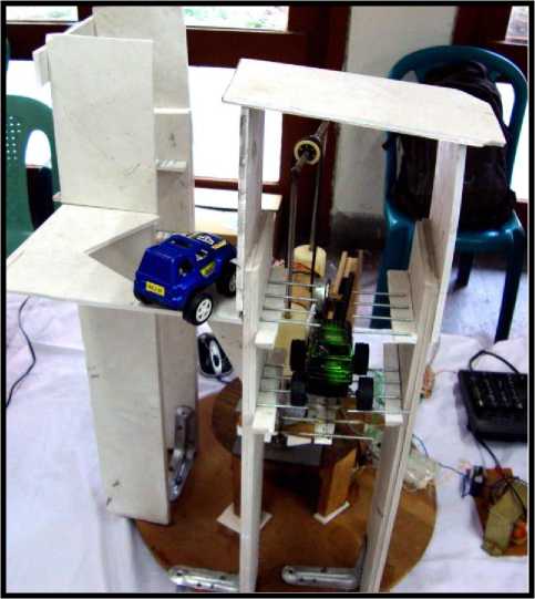
Fig. 2: Overall structure (prototype) of the parking system .
-
A. Rack and Pinion
A rack and pinion (Fig. 2) is a pair of gears which convert rotational motion into linear motion. The circular pinion engages teeth on a flat bar – the rack. Rotational motion applied to the pinion will cause the rack to move to the side, up to the limit of its travel. For example, in a rack railway, the rotation of a pinion mounted on a locomotive or a railcar engages a rack between the rails and pulls a train along a steep slope.
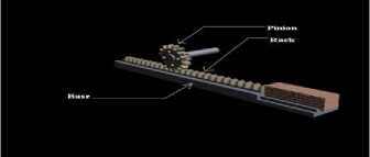
Fig. 2: Rack mechanism design with car compartment.
-
B. Timing Belt with Toothed Pulley
A Timing belts, (also known as Toothed, Notch, Cog, or Synchronous belts) are a positive transfer belt and can track relative movement. These belts have teeth that fit into a matching toothed pulley. When correctly tensioned, they have no slippage, run at constant speed, and are often used to transfer direct motion for indexing or timing purposes (hence their name). They are often used in lieu of chains or gears, so there is less noise and a lubrication bath is not necessary. Camshafts of automobiles, miniature timing systems, and stepper motors often utilize these belts. Timing belts need the least tension of all belts, and are among the most efficient. They can bear up to 200 hp (150 kW) at speeds of 16,000 ft/min.
-
C. Shaft and Plastic Wood
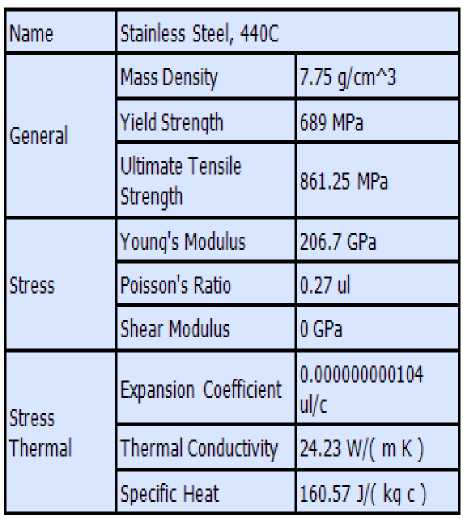
Two circular long shafts have been used to control the vertical movement of plate over which a steeper motor and a web cam have been attached .These shafts are made of Stainless steel. Stainless steel differs from carbon steel by the amount of chromium present. Carbon steel rusts when exposed to air and moisture. This iron oxide film (the rust) is active and accelerates corrosion by forming more iron oxide. Stainless steels have sufficient amounts of chromium present so that a passive film of chromium oxide forms which prevents further surface corrosion and blocks corrosion from spreading into the metal’s internal structure. Plastic wood has been used to make the main frame of our project. It is environment friendly and easy to give any complicated shape simply by cutting with anti- cutter. But it soaks up water as it is mixed with organic wood fibers. The major advantage of this category of materials is its ability to add another stage of upstream use to materials previously considered waste lumber.
-
D. Bearing and insulated copper wire
Here ball bearing is used. It’s been used in the crossing bar. It helps to rotate the shaft with the help of a motor. Insulated copper wire was used as the connecting wire. Two sets of spur gear-pinion were used for transmitting power from motor to shaft.
-
IV. ELECTRICAL ARRANGEMENT
Electrical arrangement is also very important for this system. The electrical system is briefly described here.
-
A. Stepper Motor
A stepper motor (or step motor) is a brushless, synchronous electric motor that can divide a full rotation into a large number of steps. The motor's position can be controlled precisely without any feedback mechanism (Open-loop controller) , as long as the motor is carefully sized to the application.
-
B. Optocoupler IC
A lot of electronic equipment nowadays are using optocoupler in the circuit. An optocoupler or sometimes refer to as optoisolator allows two circuits to exchange signals yet remain electrically isolated. This is usually accomplished by using light to relay the signal. The standard optocoupler circuits design uses a LED shining on a phototransistor-usually it is a n-p-n transistor. The signal is applied to the LED, which then shines on the transistor in the IC. The light is proportional to the signal, so the signal is thus transferred to the phototransistor.
-
C. Pressure Sensor
Pressure sensor is used for the safety of the smooth running of the system. Here the pressure sensor MPXV 5050gp is used to determine if there is any overweight vehicle. MPX5050GP piezoresistive transducer is a monolithic silicon pressure sensor (Fig. 3) that combines advanced micromachining techniques, thin–film metallization, and bipolar processing to provide an accurate, high level analogue output signal that is proportional to the applied pressure. The MPX5050/MPXV5050G series pressure sensor [5]-[6] operating characteristics and internal reliability and qualification tests are based on use of dry air as the pressure media.
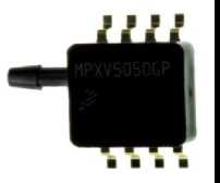
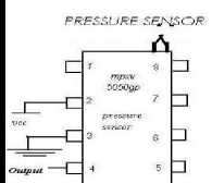
Fig 3: Pressure Sensor and Pin Diagram.
-
V. CONTROL SYSTEM
A well developed control system is necessary to combine all the process. The control system is designed as an integrated intelligence system. The control system contains code, to perform all the tasks.
-
A. Stepper Motor Control
We have a very simple circuit (Fig. 4). This circuit is used to move the motor as signaled from the computer. The circuit for a motor contains a ULN2803 and four optocouplers. The circuit is connected as shown in the
circuit diagram below. When a signal comes to first pin of the ULN2803, it amplifies the current and 12 volt pulse is supplied to the motor and it rotates one step of 1.8 degree. The next comes to the second pin, and causes another step rotation. As the ULN pin keeps getting sequential signal, the motor keep rotating. The number of is signal required is set by the program and the motor is controlled. The same thing is done for another motor. Two motors are used here. One is for the vertical movement of the platform and another for identifying the container.
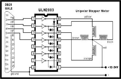
Fig. 4: Pin configuration of Stepper Motor Control with PC parallel port.
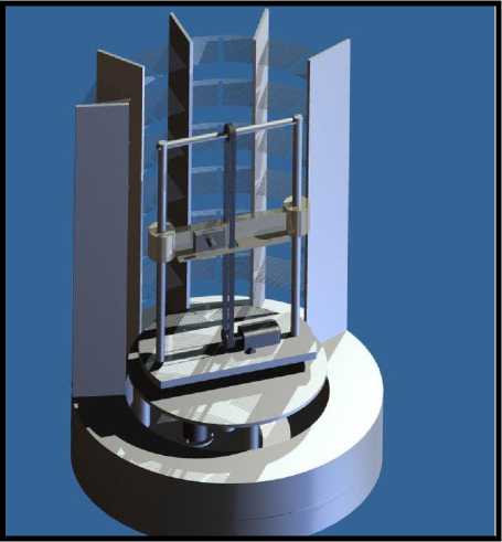
Fig. 5: Overall Design.
-
B. PC Parallel Port
The Parallel Port is the most commonly used port for interfacing. This port will allow the input of 5 to 8 bits or the output of 12 bits at any given time. The port is composed of 4 control lines (C0 to C3), 5 status lines (S3 to S7) and 8 data lines (D0 to D7). The others are ground. It's found commonly on the back of our PC as a D-Type 25 Pin female connector. There may also be a D-Type 25 pin male connector.
-
C. Pressure Sensor Control
A pressure bag is used here under the basement where the loads of the vehicles are measured. Whenever a vehicle stays on the stage it then gives a pressure to the pressure bag. The pressure bag which is filled with dry air is then compressed and gives the input of the pressure sensor. The pressure sensor was calibrated according to weight. Here the maximum allowable stress is calculated and by this overloaded vehicles are identified.
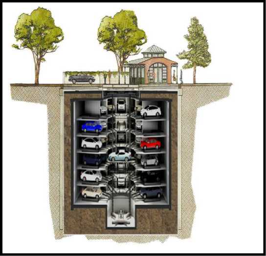
Fig. 6: Proposed Underground Design.
-
VI. SYSTEM EVALUATION
The mechanical (Fig.5 and Fig. 6) design and all the simulation was done in the software AUTODESK INVENTOR 2010 and COMSOL.The design is discussed here -
- A. Module 1:
Here the lifting mechanism is controlled by a stepper motor showing in the picture. The car compartments are arranged like a cylindrical shape so that the less space is required to park more cars (Fig. 7 and Fig. 8). The angle of rotation is controlled by another stepper motor setting under the base. It basically controls the base or the lifting structure to rotate to the orientation of the empty compartment.
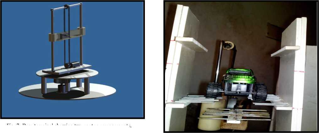
Fig. 7: Base terminal showing two motor arrangements.
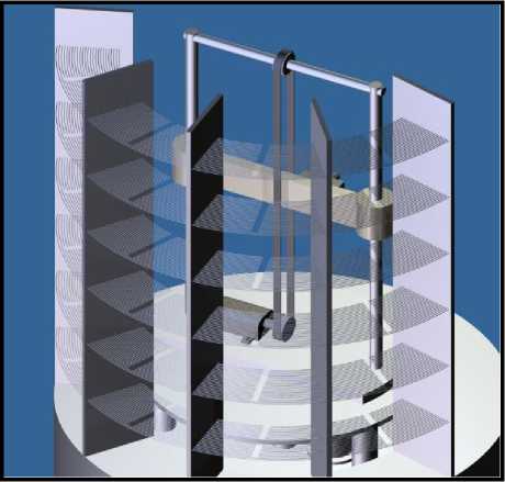
Fig. 8: Backside View of the design.
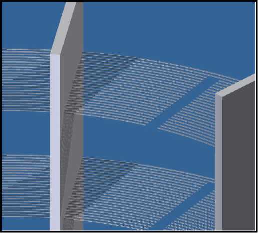
Fig. 9: Car compartment design.
-
B. Module 2:
To lift a car and place it on the empty compartments is a difficult task. Specially to place the (Fig. 9 and Fig. 10) car on the compartment generally robotic arm or gripping mechanism is introduced in the current parking systems. But here the compartments are designed in such a way so that no extra other mechanisms are needed. The third stepper motor which is on the moving base is used to control the rack-pinion mechanism to place the cars on the empty compartments. The compartments are designed (alternate of rack mechanism) such that the rack can easily place the car on the empty compartment and comes down between the empty paths of the compartment showing below-
Fig. 10: Car compartment arrangement for the rack-pinion mechanism.
-
VII. DESIGN and SIMULATION
Here a stress analysis simulation is also done to design the rack mechanism using commercially available software COMSOL 4.0a. The position and value of maximum stress, strain and displacement is also determined. The design is simulated for 1470kg force. The boundary condition of the mechanism is set for fixed-free support (Cantilever Beam). The simulated design and the input loads are shown in table I and table II.
Table I Input loads for simulation

Table II Mechanical Properties of Material
VIII. SIMULATON RESULT
From the analysis the maximum stress is determined 77.678 MPa (1st Principal Stress); displacement is 24.6615 mm. Von-Mises stress is 72.18 MPa Fig. 11 and Fig. 12. The minimum and maximum stress; strain and displacements are shown here in the table III.
Table III Result of the simulation
|
Name |
Minimum |
Maximum |
|
Von Mises Stress |
0.000417269 MPa |
72.18 MPa |
|
1st Principal Stress |
-24.8863 MPa |
77.678 MPa |
|
3rd Principal Stress |
-76.4564 MPa |
22.6821 MPa |
|
Displacement |
0 mm |
24.6699 mm |
|
Safety Factor |
9.54558111 |
15111 |
|
Stress XX |
-27.3378 MPa |
26.9857 MPa |
|
Stress XV |
-4.13356 MPa |
3.6326 MPa |
|
Stress XZ |
-10.2581 MPa |
11.544 MPa |
|
Stress YY |
-27.3378 MPa |
25.3366 MPa |
|
Stress YZ |
-14.6704 MPa |
9.69362 MPa |
|
Stress ZZ |
-73.9133 MPa |
77.3593 MPa |
|
X Displacement |
-0.0126924 mm |
0.0323036 mm |
|
Y Displacement |
-24.6615 mm |
0 mm |
|
Z Displacement |
-0.648518mm |
0.57778 mm |
|
Equivalent Strain |
0.00000000201846111 |
0.000306166111 |
|
1st Principal Strain |
-0.000000229037 ul |
0.000357837111 |
|
3rd Principal Strain |
-0.00030226111 |
0.0000000621333111 |
|
Strain XX |
-0.0000920026111 |
0.0000791572111 |
|
Strain XY |
-0.0000253973111 |
0.0000223193111 |
|
Strain XZ |
-0.0000630275111 |
0.0000709286111 |
|
Strain YY |
-0.000101309111 |
0.000080542111 |
|
Strain YZ |
-0.0000901372111 |
0.0000595592111 |
|
Strain ZZ |
-0.000301424111 |
0.000351943111 |
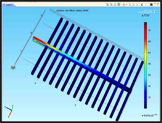
Fig. 11: Von-Mises stress distribution.
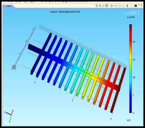
Fig. 12: Maximum deflection analysis.
IX. I MAGE P ROCESSING U SING OPTICAL CHARACTER RECOGNITION T ECHNIQUE
A complete image processing system is tried to develop here. Image processing software is developed by MATLAB software using template matching method. The templates of all the character will be define with some test point. The character which wishes to be recognized will be compare with those templates [7]-[12]. The template with the highest matched point will be the character appears in that image. The system is capable to recognizing car plate number automatically. After recognition, the plate number will be compared with the list of plate numbers in a database (fig. 13 and fig. 14).
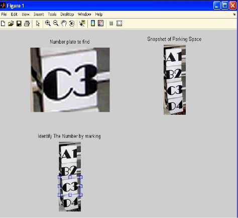
Fig. 13: Number plate Identification by blue Rectangle mark.
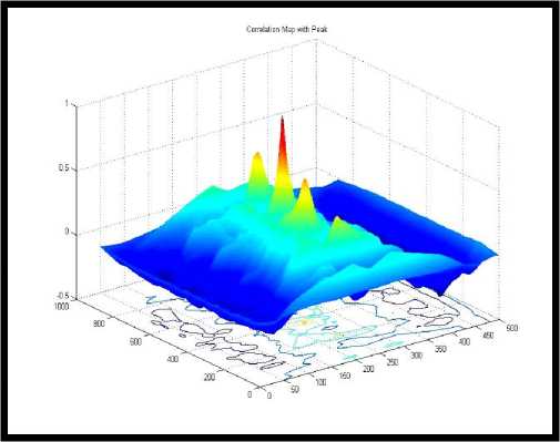
Fig. 14: Image processing after cropping and segmentation.
-
X. CONCLUSION
An advanced car parking system is fabricated and developed in this system using locally available material. The design is obviously an efficient one because compared to other existing design it can handle more cars in a limited space. The lifting mechanism is also simpler and cost effective. From the simulated result it can be shown that the structure can be designed and implemented for the parking of any type of vehicles.
ACKNOWLEDGEMENT
References Smart Parking System with Image Processing Facility
- M. Wada K.S. Yoon,H. Hashimoto, “Development of Advanced Parking Assistance System,” IEEE Transactions On Industrial Electronics, vol. 50, pp. 4-17, February 2003.
- E. S. Kardoss, K. Baliant, I. Wahl, “Design of a Semi-Aautonomous Park Assist System,” Proceedings of The European Control Conference,2009, pp. 497-516.
- J. Pohl1, M. Sethsson, P. Degerman, and J Larsson, “A semi-automated parallel parking system for passenger cars”, Proc. IMechE Vol. 220 Part D: J. Automobile Engineering, 2006, pp. 53.
- C. W. Cheng, S. J. Chang, and T. H. Li, “Parallel-parking control of autonomous mobile robot,” in Proc. Int. Conf. Industrial Electronics, and Control, and Instrumentation, Tokyo, Japan, 1997, pp. 1299–1304.
- T.L. Floyd, Digital Fundamentals, 8th ed.,2009, pp. 288-340.
- www.alldatasheet.com/MPXV5050 gp.
- M. Y. Idris, E. M. Tamil. Z. Razzak, N. M. Noor, “Smart Parking System Using Image Processing Techniques,” Journal of Information Technology, 2009, pp. 114-127.
- R.C. Gonzalez, R. E. Woods and S.L. Eddins, “Digital Image Processing Using Matlab,” 2nd ed., 2010, pp. 489.
- R. A. Lotufo, A. D. Morgan, and A. S. Johnson, “Automatic number plate recognition,” Inst. Elect. Eng.
- Colloquium on Image Analysis for Transport Applications, pp. 6/1–6/6, 1990.
- T. R. Cimmins, W. M. Brown, “Image Algebra and Automatic Shape Recognition,” IEEE Transaction Aerospace and Electronic Systems, vol AES-21 No. 1, January 1985.
- A. S. Johnson, B. M. Bird, “Number plate matching for automatic vehicle identification,” IEE Colloquium on Electronic Image and Image Processing in Security and Forensic, 1990.
- A.A. Rokoni, M.F. Ismail, M.O. Reza, M.A.R. Sarkar, “Development of an Image Processing Based Container Traffic Control System”, International Conference on Mechanical, Automotive and Aerospace Engineering-ICMAAE-2011, Paper ID-13, Kuala Lumpur, Malaysia, 17-19 May, 2011.
