SMS Tracking System with Doppler Radar to Enhance Car Security for Intelligent Transport System
Author: Subhankar Shome, Rabindra Nath Bera
Journal: International Journal of Intelligent Systems and Applications(IJISA) @ijisa
Article in issue: 2 vol.7, 2015.
Free access
The World report on road traffic injury prevention presents some assessments and conclusions regarding road traffic accidents, in which they state that more than 1.2 million deaths per year occur on the world’s roads and around 50 million more of injured people. To prevent this people are working for intelligent transport system (ITS). ITS is trying to make an intelligent car which will be able to avoid collation. In this paper we have tried to add a new goal in ITS system which will be activated in the intelligence fails. This SMS system will help to locate a car using GPS, if the car collides. Our total development work is divided into two parts. In first part we have tried to develop a system which will help the driver by providing the road scenario using dopple radar. Doppler radar will measure the velocity of the nearby car or passing by car, depending upon the information our car will be controlled. In second part of development we have developed a auto generated SMS sending system to a specific number if the Car collide. Both systems are described in details in next part of this article.
Doppler, ITS, Radar, GPS, GSM
Short address: https://sciup.org/15010659
IDR: 15010659
Text of the scientific article SMS Tracking System with Doppler Radar to Enhance Car Security for Intelligent Transport System
Published Online January 2015 in MECS
Heavy traffic condition and accident occurrence is the major problem in today’s world within our limited resources [1]. One solution of this problem is to increase the capacity by increasing the number of lane miles. At the present time, roads are being built at about two-thirds this rate [2]. A second option is to develop alternatives that increase capacity by improving the efficiency of the existing transportation system. This option focuses on building fewer lane-miles, while investing in Intelligent Transportation Systems (ITS) infrastructure [3][4].
In general the goals of ITS include the following: [5]
-
• Enhance public safety;
-
• Reduce congestion;
-
• Improved access to travel and transit information;
-
• Generate cost savings to motor carriers, transit operators, toll authorities, and government agencies; and
-
• Reduce environmental impacts.
After all above it is not ensured, that we can reduce 100% road collision, in this article we are considering on
50 million people who are getting injured on road, it is very much important to know the condition and mainly the car location, where this accident was happened for a quick rescue. Basically we are trying to add a point on ITS goal, which is location detection or information of damage car for family member and rescue team through a SMS service [6].
This development has two different angles, in fast part of this article we have concentrated on the collision avoidance using Doppler radar; in Section II we have discussed the Doppler radar part. In second part we have concentrated on car location detection using GPS and the location information sending through SMS, which is described in Section III. Section IV is discussed about the integrated system with Radar and tracking system, it is basically about the whole system and how it is working. In Section V we have shown all the results for all the experiments related Doppler radar and SMS tracking system. In Section VI we have concluded our work.
-
II. Car Detection Using Doppler Radar
A Doppler radar [7] is specialized radar that makes use of the Doppler Effect to produce velocity data about objects at a distance. It does this by beaming a microwave signal towards a desired target and listening for its reflection, then analyzing how the frequency of the returned signal has been altered by the object's motion. This variation gives direct and highly accurate measurements of the radial component of a target's velocity relative to the radar. Doppler radars are used in aviation, sounding satellites, meteorology, police speed guns, radiology, and bistatic radar (surface to air missile).
Partly because of its common use by television meteorologists in on-air weather reporting, the specific term "Doppler Radar" has erroneously become popularly synonymous with the type of radar used in meteorology. Most modern weather radars use the pulse-doppler technique to examine the motion of precipitation, but it is only a part of the processing of their data. So, while these radars use a highly specialized form of Doppler radar, the term is much broader in its meaning and its applications.
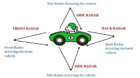
Fig. 1. Radar Systems in a Car
-
A) Doppler Effect
The Doppler effect (or Doppler shift) [8], is the difference between the observed frequency and the emitted frequency of a wave for an observer moving relative to the source of the waves. It is commonly heard when a vehicle sounding a siren approaches, passes and recedes from an observer. The received frequency is higher compared to the emitted frequency during the approach, it is identical at the instant of passing by, and it is lower during the recession. This variation of frequency also depends on the direction the wave source is moving with respect to the observer; it is maximum when the source is moving directly toward or away from the observer and diminishes with increasing angle between the direction of motion and the direction of the waves, until when the source is moving at right angles to the observer, there is no shift.
Since with electromagnetic radiation like microwaves frequency is inversely proportional to wavelength, the wavelength of the waves is also affected. Thus, the relative difference in velocity between a source and an observer is what gives rise to the Doppler effect.
-
B) Doppler Effect Associated with Moving Targets
For a fixed target, the relationship between the phases of the transmitted pulse and the echo pulse considered at the site of radar set remains the same for successive pulses. On the other hand, the relative phase of the echo signals received from a moving target continually changes relative to the phase of the transmitted pulse because of the continually changing distance of the target from the radar set [9]. Thus leta moving target move a distance R in time interval dt . This will cause the relative phase of the return edechoes to shift by an amount φ radians given by the following relation.
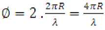
Where λ is the wavelength expressed in the same units as R. This continuous change in the phase of the echoes received from a radically moving target causes the frequency to the echoes to differ from that of the outgoing pulses. The shift fd in the frequency, referred to as the Doppler shift is given by the relation, fd = 2Л = 2/£Л (2)
Л с where,
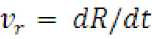
is the radial velocity (meters/seconds).
The rate of change of φ with time is the angular frequency ω d = 2π f d , where f d is the doppler frequency shift.
d0
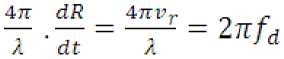
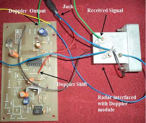
Fig. 2. Radar set up
-
C) Doppler Radar
Doppler radar was used to detect the object which sends out continuous wave signals. These signals were reflected back on hitting the target. The reflected signals were further processed in Matlab to extract the velocity with which the object was moving. Radar with a Doppler module has been shown in the Fig.2 which is used in the experiment for velocity estimation.
The output from the Doppler module is in terms of frequency domain and this is connected with a jack. This jack is connected to the audio in port in the PC (Personal Computer). This analog input can be seen in the Matlab with the help of win-sound command. The front view of the Radar with transmitter and receiver is shown in the Fig 3.
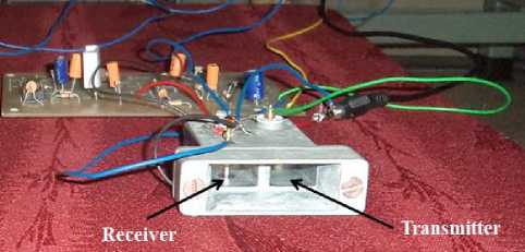
Fig. 3. Front view of Doppler radar
-
III. GPS Based SMS System
This part of works presents an automotive localization system using GPS and GSM-SMS services. This system is initiated by the radar signal. The system permits localization of the automobile and transmitting the position to the owner to a specific or predefine mobile phone as a short message service (SMS) automatically. The main aim of this project is to continuously monitor a moving vehicle and report the status of the vehicle on emergency. This tracking system is composed of a GPS receiver, Microcontroller and a GSM Modem. GPS
Receiver gets the location information from satellites in the form of latitude and longitude. The Microcontroller processes [10] this information and this processed information is sent to the user/owner using GSM modem. The proposed solution can be used in other types of application, where the information needed is requested rarely and at irregular period of time (when requested). This system interfaced with Vehicle airbag system. This enable it to monitor the accident situations and it can immediately alerts the police/ambulance service with the location of accident [11].
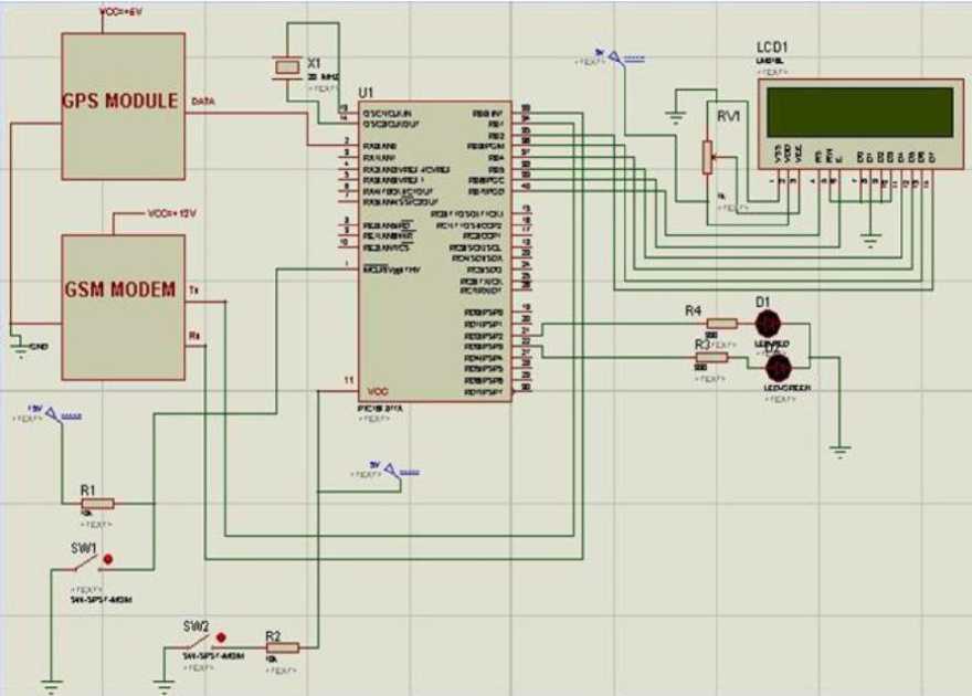
Fig. 4. Circuit Diagram of SMS based system
-
A) Circuit Diagram
The below circuit diagram of GPS and GSM based [12] Vehicle tracking System explains the interfacing section of each component with micro controller and GPS module for the location which is to be identified. The GPS receiver is connected to microcontroller in such way that one pin of GPS is connected to the pin number 2 of the microcontroller. As known the GPS receiver take the Information/signal from the GPS satellite .The output of GPS receiver is in the serial form, in the serial communication baud rate is important consideration to extract the serial information in parallel form. In our case the baud rate for GPS receiver is 4800. The GPS receiver has three terminals namely VCC, GND and DATA lines. GPS receiver requires +5 as VCC to operate normally. The GSM modem is connected to microcontroller in such way that two pins of GSM connected to the 33rd and 344th pins of microcontroller .In this article the main role
of the GSM modem is to send the text message to the another GSM mobile. The output of GSM modem is in the serial form; in the serial communication baud rate is important consideration to extract the serial information in parallel form. In our project the baud rate for GSM modem is 9600.The GSM modem has four terminals namely Tx, Rx, Gnd. The Switch is connected to microcontroller in such way that one pin of switch connected to the Ground and another pin is connected to resistor one end .Another end of resistor is connected to 32nd of microcontroller as shown in figure 4. Whenever this is made ON text message will send through GSM Modem to another mobile messaging that vehicle is crashed at particular latitude and longitude. The LCD is connected to microcontroller. LCD is interfaced in the 4 bit mode, so only four pin carry data from microcontroller to LCD. LCD is used to show latitude and longitude which is obtained from GPS receiver. [13]
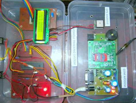
Fig. 5. Designed Circuit of SMS based system
V. Results & Discussion
A) Processing of audio signal to extract velocity
The received audio signal is fed to the PC with the help of microphone in port as shown in the Fig 2. This audio signal is processed in the Matlab to extract the velocity. The audio signal with target and without target has been shown in the fig 7 and 8 respectively. When there was no object in front of the radar, the audio signal was almost uniform without any fluctuation. But when there was a moving target in front of the radar, there was observable fluctuation in the audio signal which proved the sensing of the moving object. The fluctuations in the signal are due to the phenomenon of Doppler effect. This audio signal is further processed to extract the velocity of the moving object by estimating the Doppler shift.
-
IV. Flow Chart of Whole Concept
In this flow chat we have described the total system flow working together, as our work is divided into two parts; one is Radar and another SMS tracking system. Our prime job is to initialize both the system to get inputs from the environment. Our SMS tracking system is working based on the Radar data so First Radar will start it operation and measure all the nearby or passing by Car data for Car assistance, If in any case a nearby or passing by car distance is very low or the Car will collide in the road, and in by any chance the air bags of the car are open, then at that moment the SMS tracking system will take the GPS coordinate of the Car and will SMS the information to a specific Mobile number, so that a person can take emergency action at the earliest. Our whole system is designed on the above concept and which is show through this Figure 6 flow chart [14] [15].
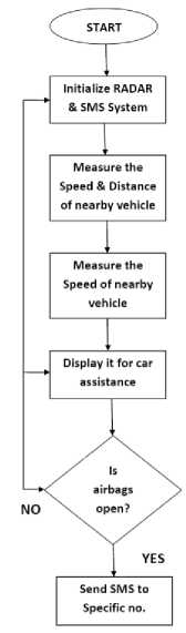
Fig. 6. Flow Chart of implemented system
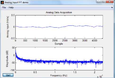
Fig. 7. Audio signals without any moving object
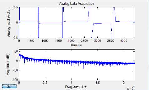
Fig. 8. Audio signals due to moving object.
:09:25
lent has send - velocity = 0 km/hr at 12-05-2012 13:09:26
lent has send - velocity = 0 km/hr at 12-95-2012 13:69:27
lent has send - velocity = 25.454572 km/hr vehicle count = 13 at 12-65-2912
:69:28X lent has send - velocity = 6 km/hr at 12-95-2612 13:09:29\ lent has send - velocity = 0 km/hr at 12-95-2012 13:09:39\ lent has send - velocity = 0 km/hr at 12-95-2912 13:09:31 Vehicle detected lent has send - velocity = 6 km/hr at 12-95-2912 13:99:32
Lent has send - velocity = 0 km/hr at 12-95-2912 13:09:33
lent has send - velocity = 9 km/hr at 12-05-2912 13:09:34
lent has send - velocity = 0 km/hr at 12-05-2012 13:09:35 Vehicle detected lent has send - velocity = 6 km/hr at 12-95-2012 13:09:36/
Lent has send - velocity = 0 km/hr at 12-95-2012 13:09:37/
Lent has send - velocity = 0 km/hr at 12-95-2012 13:09:38
Lent has send - velocity = 23.826663 km/hr vehicle count = 14 at 12-65-2012
:09:39
Lent has send - velocity = 6 km/hr at 12 95 2012 13:09:49
Fig. 9. Valid reception of the vehicle velocity crossing the radar
-
B) Static Condition Implementation
In this case the vehicle containing the radar was kept in a static position as shown in the fig 10 and the radar was placed near the glass window and the velocity of the vehicles passing by along with the vehicle count was obtained. When there was no vehicle on the highway the radar did not sense anything and thus the resultant velocity was zero. But when there was a moving vehicle passing by radar, it sensed the vehicle and velocity of the vehicle was estimated along with the vehicle count and the time at which the vehicle crossed the radar. The valid reception of the vehicles speed and the vehicle count is shown in the fig 11.
For the static condition successful results were obtained as it sensed all the vehicles which crossed the radar having velocity greater than 15km/hr. The false alarm in this case was nearly zero and satisfactory results were obtained for this case.
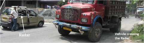
Fig. 10. Test bed at NH-31A
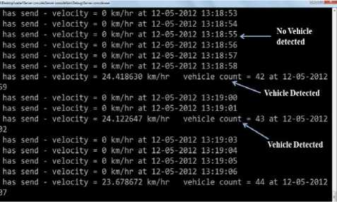
Fig.11. Detection of vehicle without any false alarm
-
C) Moving Condition Implementation
In this case the vehicle containing the radar was in motion as shown in the fig. 12 and the velocity of the vehicles passing by along with the vehicle count was obtained. Since the vehicle was in motion, the static objects in the surrounding like lamppost, trees, etc. had relative motion with respect to the vehicle. This relative motion sometime affected the sensing of the radar causing many false alarms. These lamppost and trees are also known as clutters which get added with the received signal. If the cluttering problem can be estimated and resolved, RADAR can be used effectively in the implementation of ITS. The estimated velocity and the vehicle count will give an idea to the driver of the number of vehicles on the highway along with their speed and can take certain actions to avoid collision.
-
D) Front Vehicle Detection
In this case the Radar was kept facing the front vehicle and detection of that front vehicle was tried to be estimated. The radar used in the experiment is operating at a frequency of 10.69 GHz which can detect the vehicles in the range 1.5m. When the front vehicle was not in that range, the radar was not able to detect the vehicle and the velocity of that vehicle was not estimated. Successful results were not obtained in this case but if the radar signals can be amplified or is replaced by some other radar operating at a frequency of 24GHz or 77GHz then the same algorithm can be used to detect even the front vehicles.
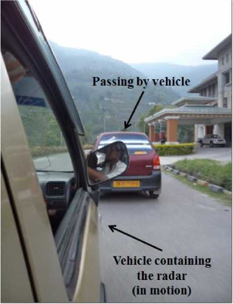
Fig. 12. Real-time implementation of RADCOM in moving condition
-
E) Results from SMS tracking System
In this article GPS and GSM based Vehicle tracking System was designed such that the location and the position of the vehicle is transmitted to the owner on his mobile phone as a short message (SMS) time using GPS and GSM modems when car airbags are open. This system also enables to monitor the accident situations and can immediately alert the police/ambulance service with the location of the accident.
-
VI. Conclusion
Overall the real time experiment of Radar with SMS tracking system was a successful one. It can be used in ITS to provide safety and to avoid collision with other vehicles also to provide information if the car collide. It can also be concluded that the collisions from three sides i.e. right-side, left-side and back-side can be prevented using the above technique. Three such radars can be placed on three sides of the vehicles and detection of any vehicle from these three sides can be sensed through the radar and the information can be displayed on the screen for the assistance of the driver. The driver can take preventive measures to avoid collision from the three sides and the number of collisions can be reduced to a great extent. For the detection of front vehicle a 77GHz Radar has to be used. Total System is tested in two parts, SMS based system is tested without airbags system of Car. Airbag systems are replaced by a switch which is producing a pulse top initiate the SMS system and a SMS is send after activating of the system in a specific number.
Referances
-
[1] World Health Organization (WHO), “World report on road traffic injury prevention”, Geneva, 2004.
-
[2] Lelitha Vanajakshi, Gitakrishnan Ramdurai and Asha Anand, “Intelligent Transportation Systems” Synthesis Report on ITS including Issues and Challenges in India, Dec. 2010.
-
[3] Qasim Siddique, “Intelligent Car System” 2009, Vol. VII fasc. 2
-
[4] ETSI TR 102 698, “Intelligent Transport Systems (ITS), Vehicular Communications; C2C-CC Demonstrator; Use Cases and Technical Specification”. V1.1.1 (2009‐06)
-
[5] Stephen Ezell, “Intelligent Transportation Systems” January 2010.
-
[6] Khondker Shajadul Hasan, Mashiur Rahman, Abul L. Haque, M Abdur Rahman, Tanzil Rahman and M Mahbubur Rasheed, “Cost Effective GPS-GPRS Based Object Tracking System”, Proceedings of the International MultiConference of Engineers and Computer Scientists 2009 Vol I IMECS 2009, March 18 - 20, 2009, Hong Kong
-
[7] Joacim Dybedal, ”Doppler Radar Speed Measurement Based On A 24 GHz Radar Sensor”, Norwegain University of Science and Technology
-
[8] http://en.wikipedia.org/wiki/Doppler_effect
-
[9] Abhinav Singh, Vaibhav Shah, Anurag Sarnaik “Moving Target Indication Radar”, International Journal of Student Research in Technology & Management Vol 1 (1), pg 2738.
-
[10] Stuart R. Ball.P.E., Embedded microprocessor systems: Real world design, embedded technology series, third edition.
-
[11] Alberto Martin, Hector Marini and Sabri Tosunoglu, “ Intelligent vehicle / highway system: a Survey” PART-1, 1999.
-
[12] Mohammad A. Al-Khedher, “Hybrid GPS-GSM
Localization of Automobile Tracking System”,IJCSIT, Vol 3, No 6, Dec 2011.
International Journal of Computer Science and Network Security, VOL.8 No.7, July 2008
References SMS Tracking System with Doppler Radar to Enhance Car Security for Intelligent Transport System
- World Health Organization (WHO), “World report on road traffic injury prevention”, Geneva, 2004.
- Lelitha Vanajakshi, Gitakrishnan Ramdurai and Asha Anand, “Intelligent Transportation Systems” Synthesis Report on ITS including Issues and Challenges in India, Dec. 2010.
- Qasim Siddique, “Intelligent Car System” 2009, Vol. VII fasc. 2
- ETSI TR 102 698, “Intelligent Transport Systems (ITS), Vehicular Communications; C2C-CC Demonstrator; Use Cases and Technical Specification”. V1.1.1 (2009‐06)
- Stephen Ezell, “Intelligent Transportation Systems” January 2010.
- Khondker Shajadul Hasan, Mashiur Rahman, Abul L. Haque, M Abdur Rahman, Tanzil Rahman and M Mahbubur Rasheed, “Cost Effective GPS-GPRS Based Object Tracking System”, Proceedings of the International MultiConference of Engineers and Computer Scientists 2009 Vol I IMECS 2009, March 18 - 20, 2009, Hong Kong
- Joacim Dybedal, ”Doppler Radar Speed Measurement Based On A 24 GHz Radar Sensor”, Norwegain University of Science and Technology
- http://en.wikipedia.org/wiki/Doppler_effect
- Abhinav Singh, Vaibhav Shah, Anurag Sarnaik “Moving Target Indication Radar”, International Journal of Student Research in Technology & Management Vol 1 (1), pg 27-38.
- Stuart R. Ball.P.E., Embedded microprocessor systems: Real world design, embedded technology series, third edition.
- Alberto Martin, Hector Marini and Sabri Tosunoglu, “Intelligent vehicle / highway system: a Survey” PART-1, 1999.
- Mohammad A. Al-Khedher, “Hybrid GPS-GSM Localization of Automobile Tracking System”,IJCSIT, Vol 3, No 6, Dec 2011.
- R.Ramani, S.Valarmathy, N.SuthanthiraVanitha, S.Selvaraju, M.Thiruppathi, R.Thangam,"Vehicle Tracking and Locking System Based on GSM and GPS", IJISA, vol.5, no.9, pp.86-93, 2013. DOI: 10.5815/ijisa.2013.09.10
- Ayeni K. Bakare and Sahalu B. Junaidu, “Integration of Radar System with GPS-Based Traffic Alert and Collision Avoidance System (TCAS) for Approach Control Separation”, Journal of Aviation Technology and Engineering 2:2 (2013) 56–62.
- Prof.N.K.Srinath, Dr.Ramakanthkumar.P, Mr. G.Prabhushankar, “Evaluation of GPS and RADAR data for Analysis of Target Tracking System”, IJCSNS International Journal of Computer Science and Network Security, VOL.8 No.7, July 2008.
