Stability analysis of individual blocks during excavation of the rock massif for a hydrotechnical facility

Author: Zafirovski Zlatko, Papikj Jovan, Peshevski Igor
Journal: Строительство уникальных зданий и сооружений @unistroy
Article in issue: 5 (32), 2015.
Free access
Purpose of the present article is to introduce an unused analyze methodology for excavation of surge tank enlargement of HEC MATKA1. Paper exposes the explanation of the way which combines the analyzing methods of non-continual and continual media. The information about existing geological and geotechnical properties presents for the numerical and analytical analyses as a basis. Several results from the stability analyses of structural controlled instabilities during the excavation of water tank are also given. The newly secondary stress- deformation state as a result from enlargement (excavation) is analyzed with program Z-SOIL. The analyze of newly secondary stress-deformation state, which is the result from enlargement (excavation), was performed with Z-SOIL program.
Water tank, excavation, rock massif, stability analysis, geotechnical properties, stress-deformation state
Short address: https://sciup.org/14322247
IDR: 14322247 | UDC: 69
Анализ устойчивости отдельных блоков во время разработки горного массива для гидротехнического объекта
Данная статья знакомит с новой, еще не вошедшей в использование, методологией анализа (HEC MATKA1) работ по выемке грунта с целью увеличения уравнительного резервуара. В статье представлены пояснения к методу анализа, объединяющему методы анализа непрерывных и дискретных данных. В основе численного и аналитического анализа лежит информация о геологических и геотехнических свойствах. В статье также приведены некоторые результаты расчета устойчивости ситуаций контролируемой потери устойчивости конструктивных решений во время выемки грунта с целью устройства водосборника. С помощью программы Z-SOIL анализируется новое вторичное состояние деформации от перенапряжения в результате увеличения (при исполнении работ по выемке грунта). Анализ нового вторичного состояния деформации от перенапряжения в результате увеличения (при исполнении работ по выемке грунта) был проведен при помощи программы Z-SOIL.
Text of the scientific article Stability analysis of individual blocks during excavation of the rock massif for a hydrotechnical facility
The arch dam Matka on a river Treska in R.Macedonia is one of the oldest constructions in a Balkan region, constructed during the beginning of 20 century after First World War. (Fig. 1) It is still an example of well designed and constructed object. During the last years, there are some ideas to improve the efficiency of all system in a term of larger production of electricity. Beside other analyses, the design of larger surge tank is necessary, which means that new excavations shall be prepared very close to the slope surface, as well as to the zone of arch dam. Having in mind the specific surroundings, the main goal of this analysis is to introduce adequate methodology for excavation of surge tank enlargement of HEC MATKA1. In this analysis information’s from the geological, geophysical and geotechnical investigations are used, and additional, some specific structural measurements are prepared in order to collect data about the joint set properties and orientation. The project analyses includes slope stability of the pre-cut, stability analyses of individual blocks during excavation, and newly secondary stress – deformation state as a result from enlargement was analysed. Finally, an adequate support system is designed [1-18].
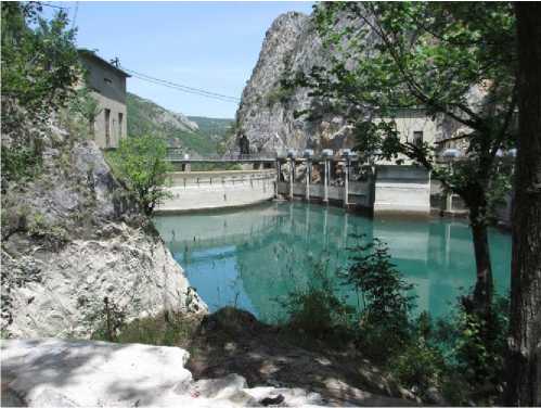
Figure1. The arch dam Matka on a river Treska
Basic geological and geotechnical data
In a frame of Project solution, the input data for geological and geotechnical properties are analyzed in order to insure reliable data for analytical and numerical analyses. An approach where a combination of the methods for analyzing of discontinued (jointed) and quasi- continual media is used. So, from the results of investigations, the following can be underlined:
The Rock Masses in an area of future excavation is built up of platy (foliated) gray to white marbles, locally with mica component concentrations.
All necessary joint properties are defined with structural-geological measurements, as a basis for analyze of structurally controlled instabilities. The range of value for marbles expressed with Rock Quality
Designation parameter is from RQD =66-82%.
Uniaxial compressive strength (for intact parts) is in a dependence of the direction of testing, and the anisotropy is evident (the strength normally to foliation planes is in a range from sc=78-86 MPa, while parallel to foliation in a range from sc=44-65 MPa. According to the Rock Mass Rating (Bieniawski,1989), the rock masses are in a class III with a value of RMR=43-49. The value of Geological Strength Index after Hoek and Brown classification is in a range GSI=50-59. The shear strength parameters and the deformability after the Hoek and Brown modified strength criteria, for different input parameters are in a following range:
-
a) Modulus of deformation Em=3354-7152 MPa
-
b) Cohesion C=166-379 kPa
-
c) friction angle fm=43-50o
The look of the zone for future excavation, as well as the existing shape of the thank is given in a figure 2.
Construction of Unique Buildings and Structures, 2015, №5 (32)
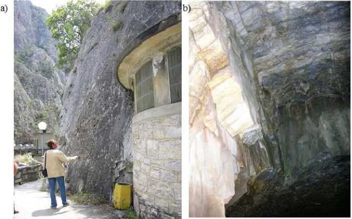
Figure 2. а) A look of the Rock Masses at the zone of future pre-cut; b) a look inside the excavation
Methods of stability and used software
In a first phase, the methods of stability analyses related to the discontinual Rock Mass media are analyzed with a help of software for wedge and plane analyses (the software packages SWEDGE and ROCPLANE are used).
For the structurally controlled instabilities in an underground, the program UNWEDGE is used. The software packages are design to incorporate different possible influences as simulation of water pressure along joints; earthquake influences etc, according to the principles of limit equilibrium methods. The additional loads as influences of blasting and earthquake are incorporated with a help of quasi-static analyses, where the dynamical forces are simulated with a help of horizontal component as a results of coefficient of horizontal acceleration (a,) as a percent of ground accelerations (g). In some cases, the input parameters are used with some variations, in order to see the effect on the factor of safety (F). Just for an illustration, a stability conditions for the enlarged excavations are given on a figure 3.
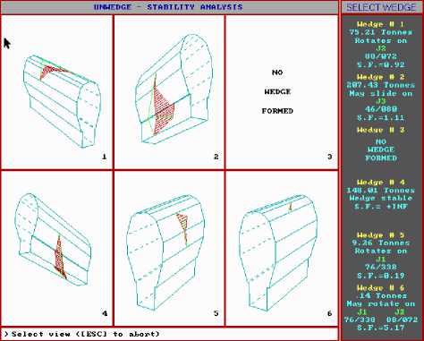
Figure 3. An overview of the stability conditions of individual wedges on a roof and sides for a case up to the final phase of excavation
Analysis of stress-deformation state in the rock massif and temporary lining with fem.
Based on detailed analyses, it was concluded that for secure excavation of surge tank enlargement, temporary lining will be used. This lining is consist of shotcrete with thickness d=8- 10cm, C-25 reinforced with welded mesh Q-335 500/560MPa, and adhesion anchors “SN” – Ø25mm, 4 meters long La=4m, at spacing ap/an=2.5/2.5m.
For numerical modelling of excavation and temporary lining of surge tank enlargement Finite Element Method (FEM) is used, incorporated in ZSOIL software produced by ZACE SERVICES Ltd (Switzerland).
The rock massif is modelled with quadrilateral FE with elastic-plastic behaviour and Mohr- Coulomb constitutive model, the existing intake tunnel with FE with elastic behaviour, and the temporary lining with beam elements.
Following parts are incorporated in the numerical model:
-
- Shotcrete lining;
-
- Concrete lining of existing Intake Tunnel;
-
- Fresh (non-weathered) Rock Mass ate the lower zones bellow surface ;
-
- Zone of altered marbles with 3.5m thickness;
-
- Excavation disturbed zone with 1.5m thickness.
As critical section from aspect of load intensity, one section at the end of the surge tank is analyzed where the overburden is Hn≈23.5m. The horizontal distance from the top arch to the surface in this section is ≈7.7m. Numerical model is presented on the following figure 4:
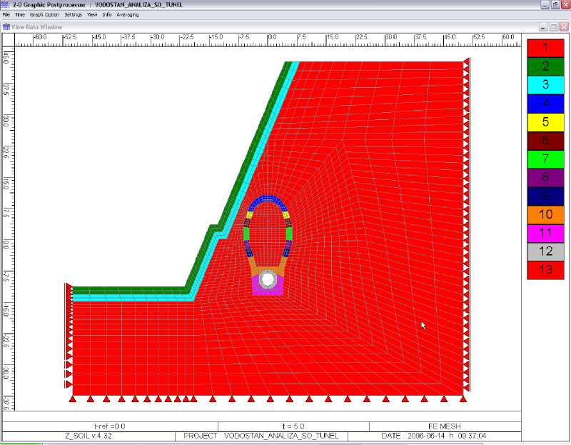
Figure 4 Numerical models for surge tank enlargement
The excavation of surge tank enlargement will be made in 8 phases. As beginning (zero step) in the analysis, the primary stress state is taken into account which exists in the rock massif before any excavation was made. At this stage in the massif primary stresses exists, and deformation are equal to zero, because they are already execute. As a result of excavation of certain phase, disturbance of primary stress state arise, and secondary stress - deformation state appears, which acts as load in the moment of setting the primary lining.
Phase excavation is modelled with introduction of Existing Functions, and Unload Functions on the parts of the numerical model where excavation was made. From the moment of excavation to the time of primary lining setting some certain time passes, and during this time certain deformations are executed, which means that surrounding rock material take over some part of the loads. According to ZSOIL recommendations, 30% of the total deformations are executed when the primary lining start to take over the loads.
Results
In the part below in graphical form, only some of results from the analysis are given. Deformed state of the model as total displacements due to excavation (without displacements from the primary stress state which are already executed), as well as internal forces in the primary lining of the surge tank are shown on the following figure:
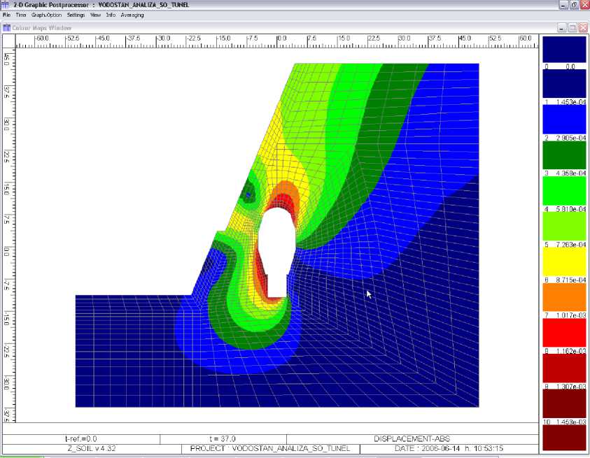
Figure 4. Total displacements of the model due to excavation of surge tank
Most important internal forces for dimensioning of shotcrete lining at the final stage of excavation are summarized in the following Table 1.
Table 1 Most inviolable internal forces in the shotcrete lining
|
Section |
N[KN] |
M [KNm] |
|
1 |
-221 |
0.7 |
|
2 |
90 |
0.2 |
|
3 |
86 |
1.7 |
In Table 2, the ultimate internal forces multiplied with partial safety coefficient (γu = 1.7), and dimensioning of shotcrete lining with thickness d=8cm, C-25MPa, reinforced with steel mesh MA 500/560 MPa, are given.
Table 2. Ultimate internal forces and dimensioning of shotcrete lining
|
Section |
Nul [KN] |
Mul [KNm] |
Necessary Reinforcement [cm2] |
|
1 |
-376 |
1.2 |
Atop=0 ; Abot =0 |
|
2 |
153 |
0.3 |
Atop =1.53 ; Abot =1.53 |
|
3 |
146 |
2.9 |
Atop =2.55 ; Abot =0.64 |
References Stability analysis of individual blocks during excavation of the rock massif for a hydrotechnical facility
- Final Report of the geotechnical investigations and laboratory tests at the location of plant Matka's powerhouse in Skopje (2004) DGR Geotehnika-ADG Pelagonija, Skopje, 895 p.
- Geophysical and seismological characteristics of the site for new tunnels and machine hall of HEC"Matka" (2005) Report MacHydro Project AD-Skopje, Skopje, 281 p.
- Bieniawski Z.T. Classification of rock masses for engineering: the RMR system and future trends In: Comprehensive Rock Engineering (1993) Pergamon Press, Vol. 3, 553-573, pp. 561-572.
- Hoek, E., Carranza C., Corcum B., Hoek-Brown failure criterion-2002 Edition, Manual from program ROCKLAB (2002) Rockscience Inc., Toronto, Canada, 428 p.
- Usmanov, R., Rakocevic, M., Murgul, V., Vatin, N. Problems of sub-mountain area development associated with collapsing loess soils (case of Tajikistan) (2014) Applied Mechanics and Materials. Vols. 633-634 pp. 927-931
- Kovačič, B., Kamnik, R., Premrov, M. Deformation measurement of a structure with calculation of intermediate load phases (2011) Survey Review, 43 (320), pp. 150-161.
- Usmanov, R., Vatin, N., Murgul, V. Highly compacted and reinforced soil beds as an efficient method to build artificial foundation based on weak soils. (2014) Applied Mechanics and Materials. Vol. 680 pp 474-480
- Premrov, M., Špacapan, I. Solving exterior problems of wave propagation based on an iterative variation of local DtN operators (2004) Applied Mathematical Modelling, 28 (3), pp. 291-304.
- Lukić, D.Č., Prokić, A.D., Brčić, S.V. Stress state around cylindrical cavities in transversally isotropic rock mass (2014) Geomechanics and Engineering, 6 (3), pp. 213-233.
- Kovačič, B., Kamnik, R., Kapović, Z. Mathematical analysis of measured displacements with emphasis on polynomial interpolation (2009) Geodetski List, 63 (4), pp. 315-327.
- Premrov, M., Umek, A., Spacapan, I. An iterative FEM for solving elastodynamics in infinite domains (2000) ZAMM Zeitschrift fur Angewandte Mathematik und Mechanik, 80 (4 SUPPL. 3), pp. S749-S750.
- Kovačič, B., Kamnik, R. Accuracy of trigonometric heighting and monitoring the vertical displacements (2007) International Journal for Engineering Modelling, 20 (1-4), pp. 77-84.
- Kovačič, B., Supej, B. The making of road body visualization for spatial verification (2004) Geodetski Vestnik, 48 (1), pp. 40-49.
- Xuan, X., Jian-Hong, W., Stamatovic, B. Iterative selection of unknown weights in direct weight optimization identification (2014) Mathematical Problems in Engineering, 2014, art. no. 572092
- Kovačič, B. Geodetical and theoretical methods for determination of movements with an emphasis on gross error detection (2004) Geodetski Vestnik, 48 (1), pp. 32-39.
- Strokova L.A. Prognoz osedaniya zemnoy poverkhnosti pri stroitelstve gorodskikh tunneley Vestnik MGSU. 2009. Vol. 4. Pp. 238-241.
- Kupriyanov A.O. Geodezicheskoye obespecheniye pri stroitelstve trassy tunneley Nauki o Zemle. 2013. Vol. 1 (9). Pp. 032-038.
- Strokova L.A. Ustanovleniye parametrov dlya prognoza osadki poverkhnosti pri stroitelstve tunneley Ekologiya urbanizirovannykh territoriy. 2009. Vol. 4. Pp. 93-99.
