Статистический энергетический метод для расчета излучения звука оконечными отверстиями систем вентиляции

Автор: Грушецкий Игорь Викторович
Журнал: Техническая акустика @ejta
Статья в выпуске: т.3, 2003 года.
Бесплатный доступ
В статье представлено применение статистического энергетического метода для расчета звуковой мощности, излучаемой оконечными отверстиями систем вентиляции. Метод позволяет рассчитать плотности энергии реверберационных звуковых полей в прямых участках воздуховодов, которые возникают в них, как в ограниченных объемах, при наличии источника звука. Показано, как составляется система уравнений энергетического баланса для системы вентиляции с произвольным числом прямолинейных участков, поворотов, разветвлений, скачков площадей поперечных сечений, оконечных отверстий. При расчете полной мощности, излучаемой из оконечного отверстия, суммируется излучение, связанное с оттоком части энергии из реверберационного поля в оконечной трубе, и излучение, обусловленное распространением из оконечного отверстия бегущих от источника звуковых волн. На примере расчета для типичной системы вентиляции показано, что уровни реверберационной составляющей излучаемой звуковой мощности могут оказаться выше уровней бегущей составляющей и, следовательно, определять шумоизлучение из оконечного отверстия.
Короткий адрес: https://sciup.org/14315987
IDR: 14315987
Sea and sound radiation from ventilating system terminations
Statistical energy analysis (SEA) application for computing of sound radiation from terminations (terminal orifice) of ventilating systems is presented. Reverberating sound field arises in air ducts as in any other enclosed space. Energy density of the reverberating sound field in terminate duct is calculated using SEA. It is demonstrated how to define power balance equations for duct system with arbitrary number of straight ducts, bends, branchings and terminations. Total sound power radiated from termination is calculated as sum of radiation of traveling waves from sources and radiation from reverberating sound field in terminal duct. As an example radiation from termination of typical ventilation system is calculated. It is shown that radiation from reverberating field in terminate duct may occur higher than radiation which comes with traveling waves from sources.
Текст научной статьи Статистический энергетический метод для расчета излучения звука оконечными отверстиями систем вентиляции
Electronic Journal «Technical acoustics»
Terminations (terminal orifice) of ventilating systems are the appreciable noise sources in human environment. Standing procedure [1] for calculation sound power radiated from terminations is based on assumption that the sound energy, radiated by fan into duct, is decreased as it propagates along ducts to termination because of dissipation, transmission via duct walls, reflection from bands, narrowings, expansions, branchings and terminal orifices, and the reflected energy is fully absorbed in ducts. However reflected energy is partly consumed to reverberating sound fields formation in ducts and finally radiated via terminations.
It was shown [2] that radiation caused by reverberating sound fields may be higher when compared to radiation induced by traveling waves from sources and standing procedure gives underestimated results. This conclusion was made after consideration of sound radiation from straight duct with one orifice and sound source at the opposite closed duct end. Ventilation systems typically consist of a lot of straight ducts, bends, branchings, narrowings, expansions, and terminations. For calculation of sound radiation from orifices of such ventilation systems statistical energy analysis (SEA) can be applied as for other complex systems as vehicles, buildings etc. [3].
ENERGY BALANCE EQUATIONS FOR DUCT SYSTEM
Let us consider duct system consisting of n straight duct, where sound energy propagates from source (fan) to terminations (only sound propagation in pipeline inner media is considered). Sound power radiated from terminations, which should be defined, less than sound power of source because of dissipation when energy propagates along ducts. Some part of total energy, reflecting from obstacles, is consumed for generation of reverberant sound fields in ducts. Some part of reverberant field energy goes from terminal orifices in outer media. Energy balance equation for duct j is the following
Wjd + ∑ Wjo = Wjs + ∑ Wji , (1) where Wjd is the sound energy dissipating in duct j ; ∑ Wjo is the energy which goes from the duct into attached ducts, Wjs is the energy which consumed for reverberant field generation and comes with traveling waves from source, ∑ Wji is the energy that comes from reverberant fields in attached ducts.
The left part of the equation describes energy outflow from duct, including inconvertible losses, the right part describes energy inflow. Absorption and energy exchange are proportional to energy of reverberant field in ducts.
Absorbing energy is equal to
Wjd = ωη jEj = ωη jVjuj = β juj , (2)
where Ej is the reverberant field energy in duct, η j is the loss factor of media oscillation inside duct, ω is the circular frequency, u j is the energy density Vj is the inner volume of duct, β j is the coefficient, which describes sound absorption in duct.
The loss factor of media oscillation inside duct can be calculated using data on decreasing of noise levels per meter when sound power propagates along duct. One can find proper information in standing procedure for fan noise calculation [1]. The formula for calculation is
∆ L p η = 2ln10 20 c ω
∆ Lp
= c ln10 20 π f , (3)
where ∆ Lp is the decreasing of noise levels per meter in straight duct, dB, c is the sound speed in media in duct.
Energy inflow and outflow are represented as
K j ∑ W j o = u j c ∑ τ kj S kj ;
K j ∑ W j i = c ∑ u k τ jk S jk , k = 1
k = 1
where τ kj and τ jk are the nondimensional coefficients of energy propagation from duct j into duct k and in the opposite direction, Sjk = Skj is the duct contact area (lesser area of cross sections of ducts j and k ), Kj is the total number of ducts attached to duct j .
Nondimensional coefficient of energy propagation from duct into another one takes into account energy reflection in junction and energy distribution between ducts in junction with branches:
bar
Tkj = TkjTkjTkj , где тЬ — transmission factor when energy propagates from duct j into duct k via band, Tkj is the transmission factor when ducts cross section area changes in junction, Trkj is the distribution factor between ducts in junction with branches. One can calculate all the factors or get ones from handbooks, for example [1].
After replacing a kj = T kjcSkj and aJk = T jkcSjk we obtain
K j
X W j = U j X a kj ;
k = 1
K j
X W j = X U k a jk , k = 1
where a kj , a jk are the dimensional (m3/c) factors describing energy propagation from duct j into duct k and in opposite direction.
Substituting ( 6) and ( 2) in ( 1) , the following equation is obtained
( Kj j
Pj+Xa uj
V
k - I
K j
- X U k a jk = W S .
k = 1
The energy entering in duct via traveling waves and expended in reverberant field formation, Wjs , is defined as
N wj = wj‘- wd -Xwni, n=1
where Wjti is the energy in traveling waves that enters into duct j , Wjd is the energy
N absorbed in duct j when traveling waves propagate in the duct, X Wnti is the energy that n=1
entered in ducts following directly after duct j , N is the number of ducts in junction after duct j .
Values Wjti , Wjd , Wnti can be calculated using well known procedures [1].
If one of duct ends is the terminal orifice then one-way energy outflow into outer media should be included in energy balance equation
(
V
K j л
Pe +Xake + a k =1 >
Kj ue -X ukaek = We , k=1
where index « е » means duct with terminal orifice, a e is the factor describing energy propagation from reverberant field in duct j into outer media.
The energy expended on reverberant field formation in duct with terminal orifice is defined as
Wes = Weti - Wed - Weto , ( 10 )
where Weto is the energy that radiated from terminal orifice via traveling waves.
Total radiated power from terminal orifice is the sum of the power radiated when traveling waves propagate out of terminal orifice, Weto (traveling part), and the power outflow from reverberant sound field in terminal duct, Wero (reverberant part).
When the traveling part of radiated power, Weto , is calculated, all losses on the way from source to orifice are taking into account:
Weto = Ws - ∑ ∆ Wd - ∑ ∆ Wr - ∑ ∆ Wrb - ∑ ∆ Wre -∆ Wro , (11)
where W s is the source radiated power, ∑ ∆ W d is the sum of inconvertible losses when traveling waves propagate along airway (transformation sound energy into heat and outflow through duct walls). ∑ ∆ W r is the sum of the losses caused by energy distribution at junctions with branches, ∑ ∆ Wrb is the sum of the losses at duct bands, ∑ ∆ Wre is the sum of the losses at drastic changes of cross section area , ∆ W ro is the losses connected with reflection from terminal orifice.
All types of losses can be calculated.
Sound power outflow from reverberant sound field in terminal duct, Wero , is calculated by the formula
W e ro = τ e ocS e u e , (12)
where τ e o is the transmission factor of energy propagation from duct into outer media, Se is the cross section area of orifice.
Density of reverberant energy in terminal duct ue depends on energy density in the rest ducts of airway. It is determined from a set of equations like ( 7) or ( 9) for all ducts of airway.
Let us give some examples.
EXAMPLES OF ENERGY BALANCE EQUATIONS FOR AIRWAYS
Energy balance equation for one duct with one terminal orifice and sound source at closed end is
( β + α o ) u = Ws - Wd - Wto . (13)
Analytical solution of this equation has been presented in [2].
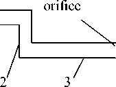
Set of energy balance equations for airway composed of three ducts (fig. 1a) is the following
( в 1 + а 21 ) и 1 - а 12 и 2 = W 1 ;
— а 21 и i + ( в 2 + a i2 + а з2 ) и 2 — а 23 и 3 = W 2 ; (14)
—а 32 и з + (вз + а 23 + а o )и 3 = W3, where W1 KW3 is the energy expended for reverberant field formation in ducts 1…3, which is entered by traveling waves.
а)
b)
c)
sound source


sound
source
sound


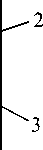
Рис. 1. Typical examples of ventilation airways
source
Right parts of the equations denoted as W 1 K W 3 are determined as follows
W 1
sdt sd sdb b
1 2 1 1 22
W2 = Ws — W1 d — W22)— W2 — Wt=
sdb d sdbdbb
1 2 2 1 2 2 33
w3 = (ws — w1 d — w2 — w2d — w3b)— w3d — w3o= sdbdb d sdbdbdee
1 2 2 3 3 1 2 2 3 3 33
where W 2 b ,3 is the power loss in traveling waves caused by reflections at bands to ducts 2 and
3, W 3 e is the power loss caused by reflection from terminal orifice of duct 3. Thus the energy that is consumed on reverberant field formation in a duct is equal to the energy reflected from “obstacle” at the end of duct, which is far from source. These losses and consequently right parts of equations can be calculated [1].
Set of equations ( 14) can be represented in a matrix form:
в 1 + а 2i
— а 21
— а 12 в 2 + а 12 + а 32
— а 32
— а 23 в 3 + а 23 + а 3
Y и 1 1
u 2
u к 3 7
2 Wi]
W 2
W, \ 3 7
or ( A - a ) U = W , where A is diagonal matrix describing energy losses in ducts, including energy outflow into attached ducts and ambient space, α is the matrix describing energy inflow into ducts. U is the column of unknown reverberant energy densities, W is the column describing the energy which enters into ducts with traveling waves.
For branching airways, presented at fig. 1(b, c), energy balance equations in matrix form are the following в1 + a 21 + a 31
- a 21
. - a 31
a i2
P 2 + « 12 + a 32 + a o
— a 32
- a 13
Y u 1
- a 23
в + a 13 + a 23 + a 3
u 2
^ u 3
A
( W '}
W 2
W.
\ 3 7
where s d t t s d s d br s d br
1 1 23 1 1 2 23
sd sdbrsdbr rr r r 1 \r г *’1 *’2 *’3/ y’ *’1 *’3 *’2 / = srrdbb bb r r । r r 2 । * ’ 3 ' * ’ 1 ' * ’ 2 ' * ’ 3 = ’ ’2’ 3 w2 = (ws - W1 d - wbr)- w2 - we =
- W 22 ) = W 2 ;
s d br d s d br d
12 2122
W3 = (ws - W1 d - Wbr)- W3d - W3e = s d br d s d br d ee
1 3 3 1 3 3 33
where W 2 br is the power loss in traveling waves at bend to duct 2 including losses caused by reflection at band to duct 2 ( W 2 b ) and losses caused by energy outflow into duct 3 ( W 3 r ), W 3 br is the power loss at bend to duct 3 including losses caused by reflection at band to duct 3 ( W 3 b ) and losses caused by energy outflow into duct 2 ( W 2 r ).
COMPUTATIONAL EXAMPLE AND DISCUSSION OF THE RESULTS
Let us calculate sound power radiated from terminal orifice of airway presented at fig. 1a. Input data are the following: diameter of cylindrical ducts is 100 mm, each duct length is 3 m, sound power of source (fan) radiated into duct is 100 dB at all frequencies. Calculations were also carried out with silencer in ducts 1, 2 or 3. Efficiency of the typical silencer of 1 m length used for calculation is given in the table.
Efficiency of the silencer used for calculation
|
frequency, Hz |
63 |
125 |
250 |
500 |
1000 |
2000 |
4000 |
8000 |
|
efficiency, dB |
2 |
5 |
13 |
17 |
12 |
10 |
8 |
7 |
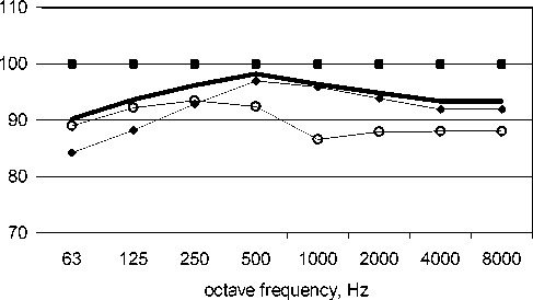
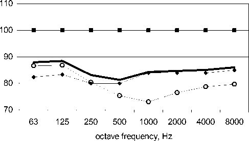
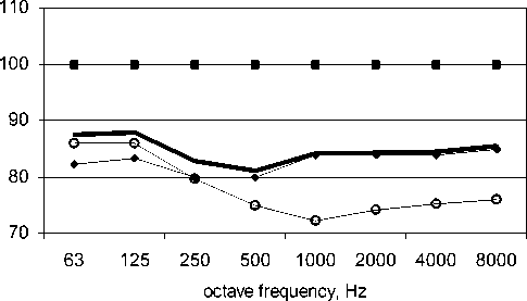
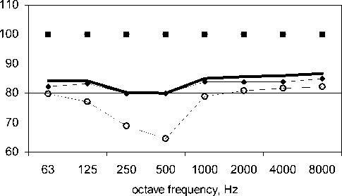
Computing results are presented in fig. 2– 6. One can see from the figures that reverberant part of sound power radiated from orifice is higher than traveling part at low frequencies (63 and 125 Hz) even if silencer is placed in duct 1 or 2. Only if silencer is placed in terminal duct, the reverberant part levels is less than traveling one at all over the frequency range 63–
8000 Hz (fig. 5). Thus, reverberant part should be taken into account in calculation of sound radiation from terminal orifices of ventilation system.
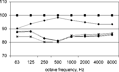
Placing the silencer in terminal duct close to terminal orifice is most efficient at low frequencies. For instance, when nominal efficiency of the silencer 1 is 2 dB at frequency 63 Hz, total decreasing of sound power from orifice is about 2 dB if the silencer is placed into duct 2 or 3, but total decreasing is 6 dB, when the silencer is placed into duct 3. The reason of higher realizable efficiency is the following. When the silencer is placed into duct 3, not only traveling power decreases, but also reverberant part of sound field in terminal duct decreases significantly. When the silencer is moved away from the terminal duct, influence of the silencer on reverberant field in this duct becomes lower.
—♦— traval.
reverb.
total
—■— fan
Fig. 2. Sound power (dB) radiated from terminal orifice of airway presented at fig. 1а when there is no silencer in airway: traveling, reverberant part, total, and fan sound power radiated into duct
—♦— travel.
reverb.
total
—■— fan
Fig. 3. Sound power (dB) radiated from terminal orifice of airway presented at fig. 1а when silencer is placed in duct 1: traveling, reverberant part, total, and fan sound power radiated into duct
—♦— travel.
reverb.
^^^^м total
—■— fan
Fig. 4. Sound power (dB) radiated from terminal orifice of airway presented at fig. 1а when silencer is placed in duct 2: traveling, reverberant part, total, and fan sound power radiated into duct
—♦— travel. reverb. total
—■— fan
Fig. 5. Sound power (dB) radiated from terminal orifice of airway presented at fig. 1а when silencer is placed in duct 3: traveling, reverberant part, total, and fan sound power radiated into duct
—♦— no silencer
—▲—1
—■— fan
Fig. 6. Total sound power (dB) radiated from terminal orifice of airway presented at fig. 1а when there is no silencer and silencer is placed in duct 1, 2 or 3 and also fan sound power radiated into duct
CONCLUSION
Reverberant sound fields in terminal ducts of ventilation airways are significant sources of radiation from terminal orifices. Sound energy density in reverberant field, which forms in terminal duct, depends on sound energy density in all other airway ducts and can be defined using statistical energy analysis (SEA). Calculation for typical ventilating system shows that sound power caused by outflow from reverberant field in terminal duct may be higher than sound power caused by traveling waves propagating from source (fan) via airway. Thus, standing procedure for sound radiation from terminal orifices may give underestimated results. Calculation also shows that for decreasing of reverberant part of radiation it is most efficient to place silencer close to terminal orifice (in terminal duct).
The method and main conclusions are apparently valid for any other duct systems: exhaust pipeline, various fluid and gas piping etc.
