Step Response Enhancement of Hybrid Stepper Motors Using Soft Computing Techniques

Author: Amged S. El-Wakeel, A. A. Sarhan
Journal: International Journal of Intelligent Systems and Applications(IJISA) @ijisa
Article in issue: 6 vol.6, 2014.
Free access
This paper presents the use of different soft computing techniques for step response enhancement of Hybrid Stepper Motors. The basic differential equations of hybrid stepper motor are used to build up a model using MATLAB software package. The implementation of Fuzzy Logic (FL) and Proportional-Integral-Derivative (PID) controllers are used to improve the motor performance. The numerical simulations by a PC-based controller show that the PID controller tuned by Genetic Algorithm (GA) produces better performance than that tuned by Fuzzy controller. They show that, the Fuzzy PID-like controller produces better performance than the other linear Fuzzy controllers. Finally, the comparison between PID controllers tuned by genetic algorithm and the Fuzzy PID-like controller shows that, the Fuzzy PID-like controller produces better performance.
Hybrid Stepper Motor, Soft Computing Techniques, Fuzzy Controller, PID Controller, Genetic Algorithm
Short address: https://sciup.org/15010566
IDR: 15010566
Text of the scientific article Step Response Enhancement of Hybrid Stepper Motors Using Soft Computing Techniques
Published Online May 2014 in MECS
Stepper motors are a type of electromagnetic mechanical devices which can convert discrete electric impulses into angular displacement or linear displacement. Their output angular displacement is directly proportional to the amount of the input pulses, and their speed of rotation is directly proportional to the frequency of the input pulses [1] . These motors possess all the advantages of standard permanent magnet (PM) synchronous machines while their cost is much lower [2] . Stepping motors are the ideal choice for those applications where power is small (less than 100 watt) while position control must be sharp and fast, such as in robotics, aerospace applications, machine tools, printers, scanners, and servos [3] .
Stepper motors have several merits such as great output torque, small inertia, and high frequency response. These features contribute to the wide usage in the industry nowadays, especially in measurement and control applications [1] . Stepper motors have also some demerits such as step response with overshoot and relatively long settling time. Besides, loss of synchronism appears when steps of high frequency are given. It is thus necessary to develop control schemes to improve the performance of stepper motors [4] .
Recently, the positioning systems are being implemented using stepper motors instead of traditionally DC motors [5] . This is because, for high speed repetitive motion, the brushes in DC motors are subject to excessive mechanical wear and consequently lead to a decrease in performance. Also, since there is a winding on the rotor of DC motors, the rotor copper loss and hence the heat does not have a direct path to the outside environment, but instead must be dissipated through the stator. Another important aerospace application of the stepper motors is that, in order to achieve uniform performance throughout the life span of more than 10 years and to avoid unpredictable and intolerable disturbances to the satellite, the stepper motors are required to deliver a constant torque [6, 7] .
In this paper, the mathematical model of the hybrid stepper motor is presented in section II. Section III reviews briefly the different FL controllers available in practice. Section IV describes the GA as a global optimization technique that can be used to tune parameters of the PID controller. The application of the different controllers to enhance the step response of the hybrid stepper motor is detailed in section V.
-
II. Mathematical Model for Hybrid Stepper
Motor
Basically, the model of the hybrid stepper motors can be expressed in forms of equations as follows [4, 8-10] :
di
L- a = - Ri a + K c ® sin(Nr 0 ) + V a dt
L ^b = - Ri + K ю cos( N д') + v dt b c r b
J d m = - i aKc Sin( N r G ) + i b K c COS( Nr G ) - T L (3)
dt dG m = dt
where v and i are the voltage and current in phase ( a ) respectively, v and i are the voltage and current in phase (b ) respectively, ω is the rotor speed, θ is rotor position angle, R is the resistance of the phase winding, L is the inductance of the phase winding, B is the friction coefficient, J is the rotor inertia, K is the motor torque constant, τ is the load torque, and N is the number of rotor teeth.
In this paper, MATLAB software is used to solve, simulate, study and investigate the motor performance subject to different conditions. The motor model [10] is shown in Figure 1.
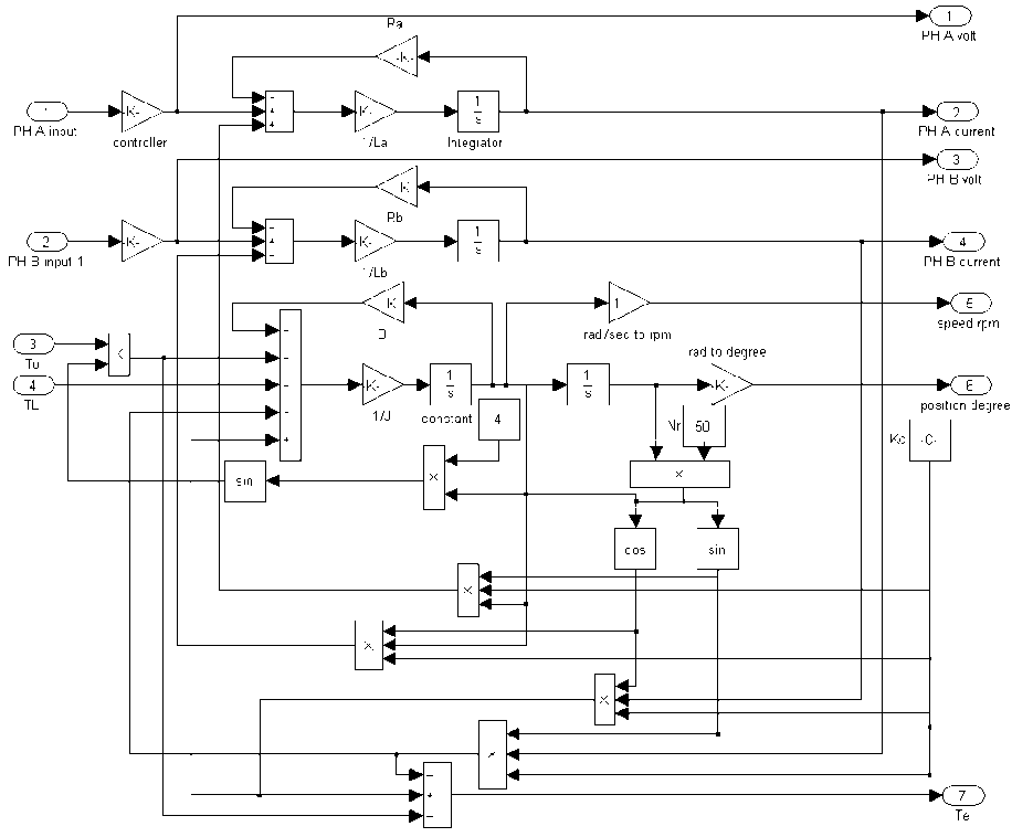
Fig. 1. Hybrid stepper motor model using MATLAB toolbox
-
III. Fuzzy Logic Controller (FLC)
The FLC provides an algorithm, which converts the linguistics control based on expert knowledge into an automatic control strategy. Therefore, the FLC algorithm is much closer in spirit to human thinking than traditional logical systems [11] . FLC provides a formal methodology for representing, manipulating, and implementing a human's heuristic knowledge about how to control a system [12] . The block diagram in Figure (2) shows a Fuzzy control embedded in a closed-loop control system. The plant output is denoted by y ( t ), its input is denoted by u ( t ), and the reference input to the Fuzzy controller is denoted by r ( t ). As shown in Figure 2, the Fuzzy control has four main components: the rule-base, the inference mechanism, the fuzzification interface, and the defuzzification interface.
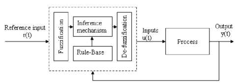
Fig. 2. Fuzzy controller architecture
The "rule-base" holds the knowledge, in the form of a set of rules (if-then rules), of how best to control the system. There are at least four main sources for finding control rules [13]: expert experience and control engineering knowledge, operator's control actions, Fuzzy model of the plant, or based on learning. The inference mechanism evaluates which control rules are relevant at the current time and then decides what the input to the plant should be. The fuzzification interface simply modifies the inputs so that they can be interpreted and compared to the rules in the rule-base. The defuzzification interface converts the conclusions reached by the inference mechanism into inputs to the plant. In brief, FLC is designed using certain steps mentioned below [14]:
-
• Define the characteristics of the plant from the operator.
-
• Apply conventional control simulation to study the system performance.
-
• Define the control variables (position, torque, speed .........etc.).
-
• Identify the input and output of FL controller.
-
• Define the universe of discourse of each input and output.
-
• Define universe of discourse, Fuzzy sets and their inputs and outputs membership functions for inputs and outputs.
-
• Determine the rules-Table (look-up Table) and the corresponding scaling factors for inputs and outputs.
-
• Simulate the system using FL controller and observe performance.
-
• Iterate the rule Table, membership functions (mfs) until the performance is satisfactory.
-
• Implement the FL controller for real time.
There are several types of linear FLC [12] : Fuzzy Proportional (FP), Fuzzy Proportional-Derivative (FPD), Fuzzy Proportional-Derivative-plus-Integral (FPD+I), Fuzzy Incremental (FI), and Fuzzy PID-like controller.
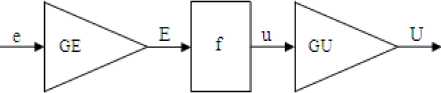
The FP controller is derived from the PID controller with the I-action set to zero — = 0 and the D-action set IT. J to zero (T = 0) where, T and T are the integral and derivative time constants, respectively. As shown in Figure 3, FP controller acts on the error ( e ), and its control signal is (U ). The FP controller has two tuning gains: error gain ( GE) and output gain ( GU ), where the crisp proportional controller has just one, K . The control signal U(n), at the time instant ( n ) is generally a nonlinear function of the inpute(n).
U ( n ) = f (GE . e( n )) . GU (5)
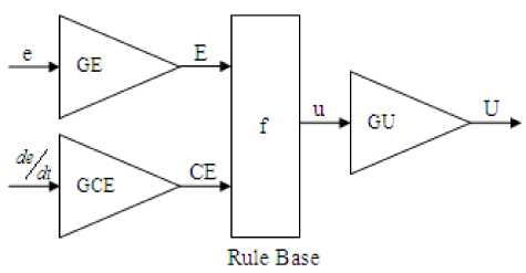
Fig. 4. FPD Controller
The control signal U ( n ), at the time instant ( n ), is a nonlinear function of error and change in error is:
U ( n ) = f (GE.e( n ), GCE.e(n)).GU (6)
where GCE is the change of error gain.
If the closed-loop system exhibits a sustained error in steady state, integral action is necessary. The integral action will increase (or decrease) the control signal if there is a positive (or negative) error, even for small magnitudes of the error. Thus, a controller with integral action will always return to the reference in steady state. A Fuzzy PID controller acts on three inputs: error, integral error, and change in error. A rule base with three premise inputs can be a problem. To overcome this problem, a simple design is to combine crisp integral action and a Fuzzy PD rule base in the Fuzzy PD+I (FPD+I) controller as in Figure 5.
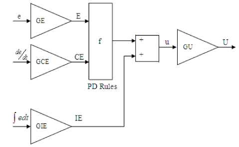
Fig. 5. FPD+I Controller
Rule Base
Fig. 3. FP Controller
The control signal U ( n ) at the time instant ( n ), is a nonlinear function of error, change in error, and integral error as:
n
U ( n ) =
f ( GE . e ( n ), GCE e ( n )) + GIE £ e ( j T
. GU (7)
The FPD type control generates control output from error and change of error as shown in Figure 4. Derivative action helps to predict the future error, and the PD controller uses the derivative action to improve closed-loop stability.
where T is the sampling time and GIE is the integral error gain.
The Fuzzy incremental controller in Figure 6 is of almost the same configuration as the FPD controller except for the added integrator. The conclusion in the rule base is now called change in output ( cu ), and the gain on the output is, accordingly, GCU.
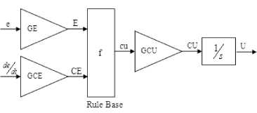
Fig. 6. Fuzzy Incremental Controller
The control signal U(n) at time instant (n ) is the sum of all previous increments and can be expressed as:
n
U ( n ) = ^ ( cu ( j ) ■ GCU - T )
j = 1
n
= £ ( f ( GE - e ( j ), GCE - e ( j )) - GCU - T )
j = 1
A Fuzzy PID-like controller is a fuzzified PID controller. It acts on the same input signals, but the control strategy is formulated as Fuzzy rules. A Fuzzy PID-like controller structure is simply formed by connecting the FPD type and FIC together in parallel as shown in Figure 7.
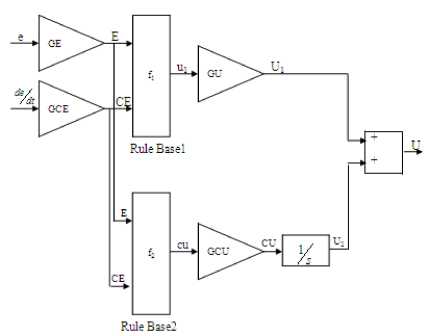
Fig. 7. Fuzzy PID-like controller Fuzzy
The control signal U ( n ), at the time instant ( n ), is the sum of U and U .
U ( n ) = U + U
= f ( GE - e ( n ), GCE - e ( n )) - GU + (9)
X ( f 2 ( GE - e ( j ), GCE - e ( j )) - GCU - Ts )
-
IV. Genetic Algorithm (GA)
GA is simple, powerful, general-purpose, derivative-free, stochastic global optimization methods inspired by the laws of natural selection and genetics. These algorithms are derivative-free, which means that they do not need functional derivative information to search for a set of parameters that minimize (or maximize) a given objective function. Instead, they exclusively rely on repeated evaluations of the objective function, and the subsequent search direction after each evaluation follows certain heuristic guidelines. In particular, the optimum solution is obtained by investigating new solutions which incorporate three genetic operations: reproduction, crossover, and mutation in a selective environment where the fittest survive [15]. There are three main steps for genetic algorithm, random initialization of population, evaluation of fitness function and finally generation of new population.
In random initialization of population, the initial population is created randomly with even number ( N ) of individuals. An individual is characterized by a fixed-length binary bit string, which is called a chromosome. In evaluation of fitness function all the individuals of the initially created population are evaluated by means of a fitness function ( f ). The fitness function is then used in the next step, to create a genetic pool. After evaluating the fitness of the individuals of the initial population, a new population is created. The creation of a new generation is performed basically in three stages, reproduction, crossover and mutation. The overall goal of this step is to obtain a new population with individuals which have high fitness values.
In reproduction stage, the individuals are selected among the population with probabilities proportional to their fitness values. In this way, individuals with lower fitness values are eliminated whilst others are copied to the next generation one or more times, and some are not copied at all. The population after reproduction stage is called mating pool.
In crossover stage, a genetic crossover operator is applied to the mating pool to generate new individuals. Thus individuals of the mating pool are paired randomly, and genetic couples are obtained. There are many crossover operators can be used but the most basic crossover operator is the one-point crossover operator, in this case a crossover point in the string bits of the selected pair is randomly chosen, and the bits of the two parents are interchanged at this point as shown in Figure 8. In two-point crossover operation, the two crossover points are selected in the binary strings of the pair under consideration and between these points the bits are swapped as shown in Figure 9. This crossover process is similar to the mating process in a biological system, where parents pass segments of chromosomes to their offspring and thus offspring can outperform their parents if they get ‘good’ genes from both parents.
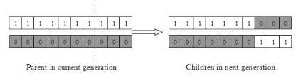
Fig. 8. One-point crossover
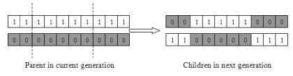
Fig. 9. Two-point crossover
The crossover process is followed by a mutation process, which introduces further changes to a bit string. This is required, since if the population does not contain all the encoded information required to solve a specific problem, no amount of gene mixing can provide a satisfactory solution. By applying the mutation operator, it is possible to produce new chromosomes. This can be implemented in various ways, and the most common technique is to change a randomly chosen bit in the bit string of the individual to be mutated. Thus certain bit is changed from 1 into 0 or from 0 into 1. Finally, it can be said that the crossover and mutation together give genetic algorithms most of their searching power [16, 17] .
-
V. Simulation Results
The hybrid stepper motor with data given in Table 1 is used in the simulation [18] . While control rules for FLC are shown in Table 2. Tables 3-5 show the control rules for self tuning of the PID controller.
Table 1. Hybrid stepper motor parameters
|
Motor phase A resistance ( Ω ) |
Ra =10 |
|
Motor phase A inductance (H) |
La =0.001 |
|
Motor phase B resistance ( Ω ) |
Rb =10 |
|
Motor phase B inductance (H) |
Lb = 0.001 |
|
Machine torque constant (Nm/A) |
KC = 0.113 |
|
Applied DC phase voltage (V) |
Vs =5 |
|
Friction coefficient (Nm S/rad) |
B = 0.00 |
|
Inertia constant (kgm2) |
J = 0.00005 |
|
Number of rotor teeth |
Nr =50 |
Table 2. Control Rules of FLC.
|
e e |
NB |
NM |
NS |
ZR |
PS |
PM |
PB |
|
NB |
NB |
NB |
NB |
NB |
NM |
NS |
ZR |
|
NM |
NB |
NB |
NB |
NM |
NS |
ZR |
PS |
|
NS |
NB |
NB |
NM |
NS |
ZR |
PS |
PM |
|
ZR |
NB |
NM |
NS |
ZR |
PS |
PM |
PB |
|
PS |
NM |
NS |
ZR |
PS |
PM |
PB |
PB |
|
PM |
NS |
ZR |
PS |
PM |
PB |
PB |
PB |
|
PB |
ZR |
PS |
PM |
PB |
PB |
PB |
VB |
Table 3. Rule base for determining the gain K
|
e e |
NB |
NS |
ZE |
PS |
PB |
|
NB |
VB |
VB |
VB |
VB |
VB |
|
NS |
B |
B |
B |
MB |
VB |
|
ZE |
ZE |
ZE |
MS |
S |
S |
|
PS |
B |
B |
B |
MB |
VB |
|
PB |
VB |
VB |
VB |
VB |
VB |
Table 4. Rule base for determining the gain K
|
e e |
NB |
NS |
ZE |
PS |
PB |
|
NB |
M |
M |
M |
M |
M |
|
NS |
S |
S |
S |
S |
S |
|
ZE |
MS |
MS |
ZE |
MS |
MS |
|
PS |
S |
S |
S |
S |
S |
|
PB |
M |
M |
M |
M |
M |
Table 5. Rule base for determining the gain K
|
e e |
NB |
NS |
ZE |
PS |
PB |
|
NB |
ZE |
S |
M |
MB |
VB |
|
NS |
S |
B |
MB |
VB |
VB |
|
ZE |
M |
MB |
MB |
VB |
VB |
|
PS |
B |
VB |
VB |
VB |
VB |
|
PB |
VB |
VB |
VB |
VB |
VB |
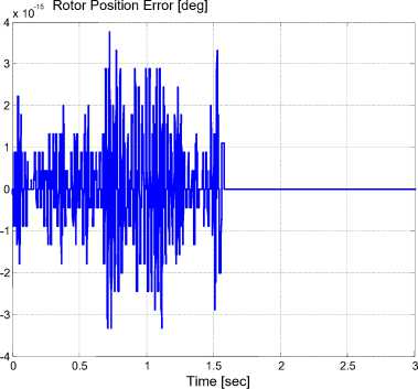
(a) Rotor position error
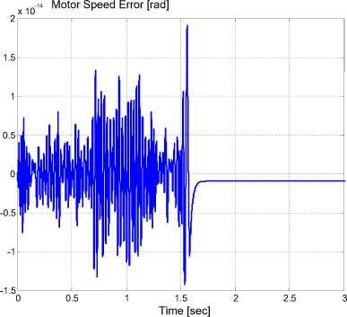
(b) Motor speed error
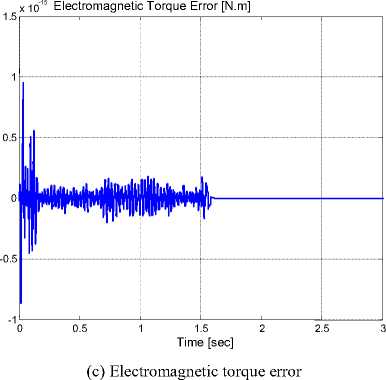
Fig. 10. Results for new model verification
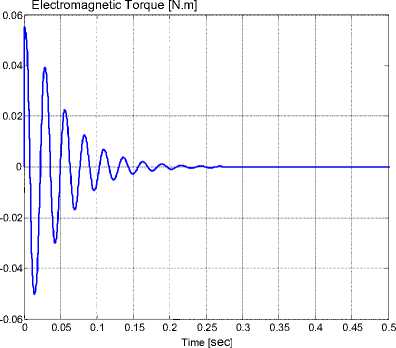
(c) Electromagnetic torque
Fig. 11. Full-step motor performance
First of all, the model is verified by comparing its response with the built-in hybrid stepper motor model obtained in MATLAB simulink toolbox. The comparison results are shown in Figure 10. It is clear from the comparison that the error in the rotor position, motor speed, and electromagnetic torque is too small and can be neglected.
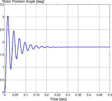
(a) Rotor position angle
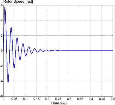
(b) Rotor speed
The hybrid stepper motor is investigated on open loop control. This investigation includes the study of the motor position, rotor speed, and electromagnetic generated torque on the shaft as shown in Figure 11.
The motor performance using PID controller with different tuning methods is compared. The tuning of the PID controller by GA is carried out using a MATLAB built-in routine so called Simulink Response Optimization (SRO) Toolbox. The SRO, automatically, formulates an optimization problem and calls a GA and direct search toolbox, as an optimization routine to solve the problem [18] . It is clear from Figure 12 that, PID controller with GA provides better performance. The three types of PID controller have no overshoot and no steady state error. PID controller with GA has the least rise time and settling time.
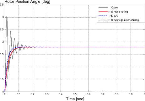
Fig. 12. Comparison between PID controllers with different tuning methods
The motor performance using different Fuzzy controllers is compared. It is clear from Figure 13 that, the best performance is obtained from Fuzzy PID-like controller. The different types eliminate the oscillation around final position, overshoot, and the steady state error. The least rise time and settling time obtained from Fuzzy PID-like controller.
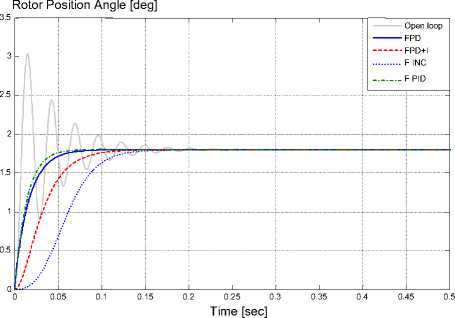
Fig. 13. Comparison between different Fuzzy controllers
Finally, the motor performance using PID with GA and Fuzzy PID-like controller is compared. It is clear from Figure 14 that, the Fuzzy PID-like controller produces better performance.
The model with Fuzzy PID-like controller is tested to verify the controller capability to follow a reference position, and the results are shown in Figure 15.
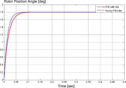
Fig. 14. Comparison between PID with GA and Fuzzy PID-Like Controller
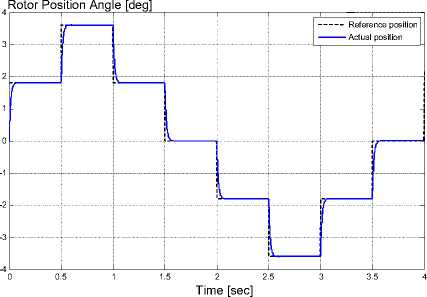
Fig. 15. Motor performance with Fuzzy PID-like controller following position trajectory
-
VI. Conclusion
Different soft computing techniques including Fuzzy logic and Genetic algorithm have been applied to improve the step response of hybrid stepper motors. The linear Fuzzy controller algorithms for closed-loop control of hybrid stepper motors have been discussed. The numerical simulations by a PC-based controller show that, the Fuzzy PID-like controller produces better performance than the other linear Fuzzy controllers.
In addition, both Genetic algorithm and Fuzzy logic are used to tune the PID controller gains. The numerical simulations show that, the PID controller tuned by Genetic algorithm produces better performance than that tuned by Fuzzy logic.
The comparison between PID controllers tuned by Genetic algorithm and the Fuzzy PID-like controller shows that, the Fuzzy PID-like controller produces better performance.
Acknowledgments
The authors would like to thank the anonymous reviewers for their careful reading of this paper and for their helpful comments.
References Step Response Enhancement of Hybrid Stepper Motors Using Soft Computing Techniques
- Zhaojin Wen; Weihai Chen; Zhiyue Xu; Jianhua Wang, "Analysis of Two-Phase Stepper Motor Driver Based on FPGA," presented at the IEEE International Conference on Industrial Informatics, August 2006.
- W. D. Chen; K. L.Yung ; K.W. Cheng, "A Learning Scheme for Low-Speed Precision Tracking Control of Hybrid Stepping Motors," IEEE/ASME Transactions on Mechatronics, vol. 11, pp. 362-365, June 2006.
- A. Bellini; C. Concari; G. Franceschini; A. Toscani, "Mixed mode PWM for high performance stepping motors," presented at the 30th Annual Conference of IEEE Industrial Electronics Society, IECON November 2004.
- Ja. Alvarez-Gallegos; E. Alvarez-Sanchez; R. Castro Linares, " Experimental setup for sensorless rotor position control of a permanent magnet stepper motor " presented at the 9th IEEE International Power Electronics Congress , CIEP 2004, , October 2004.
- M. Zribi and J. Chiasson, "Position control of PM stepper motor by exact linearization," IEEE Transactions on Automatic Control, vol. 36, pp. 620-625, May 1991.
- K. R. Rajagopal; M. Krishnaswamy; Bhim Singh; and B. P. Singh, " An Improved High-Resolution Hybrid Stepper Motor for Solar-Array Drive of Indian Remote-Sensing Satellite," IEEE Transactions on Industry Applications, vol. 33, July/August 1997.
- K.R. Rajagopal; N. Kannan; B. Singh; B. P. Singh, "An Optimized Module-type Hybrid Stepper Motor for Spacecraft Solar Array Drive," presented at the International Conference on Power Electronics and drive Systems, May 1997.
- A. Selk Ghafari and A. Alasty, "Design and Real-Time Experimental Implementation of Gain Scheduling PID Fuzzy Controller for Hybrid Stepper Motor in Micro-Step Operation," IEEE International Conference on Mechatronics, pp. 421-426, June 2004.
- J. Persson; Y. Perriard, "Steady state Kalman filtering for sensorless control of hybrid stepper motors," presented at the IEEE International Electric Machines and Drives Conference, IEMDC'03, June 2003.
- A. Sarhan; Amged El-Wakeel; A. B. Kotb, "Analysis and control of Hybrid Stepper Motor for Automatic SunTracking System," presented at the 13th International conference on Aerospace Sciences & Aviation Technology, ASAT13, Cairo, Egypt, 26-28 May 2009.
- F. Betin; D. Pinchon; G. A. Capolino, "Fuzzy Logic Applied to Speed Control of a Stepping Motor Drive," IEEE Transactions on Industrial Electronics, vol. Vol. 47, June 2000.
- Kevin M. Passino and Stephen Yurkovich, Fuzzy Control: Addison Wesley Longman, California, 1998,.
- Jan Jantzen, Foundations of Fuzzy Control: John Wiley, England, 2007.
- Hamdy Abd El-Halim Mohammad, "ANALYSIS AND POSITION CONTROL OF STEPPER MOTOR USING ARTIFICIAL INTELLEGENCE," PhD thesis, Al-Azhar University, Cairo, Egypt, 2006.
- Werner Leonhard, Control of Electric Drives: Springer, 2001.
- A. S. EL-WAKEEL, A. E. ELAWA, and Y. EL-KOTESHY, "POSITION CONTROL OF A SINGLE ARM MANIPULATOR USING GA-PID CONTROLLER, "International Journal of Electrical Engineering & Technology (IJEET), vol. 4, pp. 120 - 135, 2013.
- Yasser Said Mohmoud, "Modern Control Strategies of Electric Machines," Master of Science, M.Sc., Military Technical College, MTC, Cairo, Egypt, 2009.
- Amr Ahmed Sarhan, "Design Analysis and Simulation of Satellite Solar Cell Tracking System," Master of Science, M.Sc., Military Technical College, MTC, Cairo, Egypt, 2011.
