Studies on the performance of a GaInP/GaAs tandem solar cell at elevated temperatures

Author: Debashish Pal, Rabi Adhikary
Journal: International Journal of Engineering and Manufacturing @ijem
Article in issue: 1 vol.9, 2019.
Free access
In this paper theoretical studies have been performed on a multijunction GaInP/GaAs based tandem solar cell. The top GaInP cell and the bottom GaAs cell were investigated separately. At an operating temperature of 300K, the current matching condition is fulfilled when the top cell and bottom cell base doping concentration and thickness are set to 5x10¹⁵/cm3, 1µm, and 2x10¹⁷/cm3, 0.127µm respectively. For the purpose of the investigation, a wide operating temperature range was chosen from 25ºC to 100ºC. The optimized tandem solar cell structure having a thickness of 1.847 microns is found to have VOC=2.2996V, ISC=0.0136Amp/cm2, FF=87.61% and ɳ=27.4% under AM1.5G one sun illumination. Studies have also revealed that when the cells are analyzed separately the current mismatch is less significant at low temperatures with the difference becoming notable at higher temperatures. Simulations of the solar cell were performed using PC1D.
AM 1.5, Fill Factor, GaAs/GaInP, Open Circuit Voltage, Reverse Saturation Current, Short Circuit Current
Short address: https://sciup.org/15015872
IDR: 15015872 | DOI: 10.5815/ijem.2019.01.04
Text of the scientific article Studies on the performance of a GaInP/GaAs tandem solar cell at elevated temperatures
solar cells are lattice matched layers of different semiconductors, each layer responding to different wavelengths of the solar spectrum based on their energy bandgap [5]. The layers are so arranged such that the material with the highest bandgap is at the top with the successive layers having decreasing bandgaps. This arrangement ensures that the cell is able to respond to most of the photons having a range of energy values incident on its surface. A very important criterion of current matching must be satisfied by such tandem cells and because such tandem cells are composed of a series connection of multiple cells the total current is limited by the minimum current among the cells.
The choice of the materials for epitaxial growth plays a very significant role in determining the performance of a multijunction solar cell. Lattice-mismatched materials are detrimental to the performance of a solar cell as they result in dislocation of the atoms promoting non-radiative recombination reducing the carrier lifetimes [6,7]. ^
The theoretical temperature dependences of solar cell output parameters have been investigated in a number of different articles [8,9,10,11]. An increase in the temperature of a semiconductor affects its terminal characteristics namely the open circuit voltage (VOC), short circuit current (JSC), fill factor (FF) and the efficiency (ɳ) [12].
The electrical parameters that determine the performance of the solar cell are as follows. The External Quantum Efficiency (EQE) is defined as the ratio between the number of collected charges and the number of incident photons for each wavelength. The short-circuit current density Jsc depends on the useful absorption fraction EQE(λ) integrated over the whole spectral range and weighted by the incident spectral power density per unit area P(λ):
Jsc= q JEQE (X) p (X) X dX
where q is the electron charge, h Planck’s constant, c the speed of light.
The open-circuit voltage Voc is the voltage measured for a perfect balance between photo-generated current and dark current in a cell:
V = v OC
-------lnl q V J 0 n
+1
where k is the Boltzmann constant, T the temperature, q the elementary charge, ɳ, and J 0 are respectively the ideality and the reverse saturation current (dark current) of the diode. The Voc is thus intrinsically defined and limited by the dark current in a cell which is given by:
J о = q
where ni is the intrinsic carrier concentration, Na and Nd are the acceptor and donor atom concentrations, Dn and Dp the diffusion constants, Ln and Lp the diffusion lengths of the electrons and holes.
The fill factor FF relates the maximum power Pmax obtainable from the cell to the product of the open-circuit voltage Voc and short-circuit current Isc of the cell.
FF =
P max
sc oc
The efficiency of the solar cell is the ratio between its electrical power output and the incident power of the light entering the device.
П =
IscVocFF
Pin
-
2. Design and Optimization
-
3. Results and Discussion
The device is optimized keeping the doping concentration and thickness of the base layers in both the subcells as the variable parameters. It is found that the exact current match is obtained for the top and the bottom subcells for a base thickness and doping concentrations of 1µm, 0.127µm and 5x10¹⁵, 2x10¹⁷/cm3 respectively. The Fig.2 (a) and (b) show the current-voltage relationship and the power-voltage relationship of the top and the bottom cells. The values of the terminal parameters obtained from the results of the simulation are listed in Table 1.
This study investigates a multijunction solar cell structure having four layers in the top and the bottom subcell. The top subcell is a Ga0.5In0.5P (Eg=1.9 eV) based solar cell having three junctions with an Al0.8Ga0.2As window layer. The bottom subcell is made of GaAs(Eg=1.424 eV) based material with a Ga0.5In0.5P window and a BSF layer. The bottom subcell is mounted on a GaAs substrate and the two subcells are separated by a tunnel junction. The choice of Ga0.5In0.5P and GaAs as the materials for the proposed device allows us to optimize the absorption of the solar energy.^
For the purpose of optimization of the solar cell, the top-down approach is used. The thickness and the doping concentration of the top cell are first varied to determine the values for which it has the highest efficiency. In order for the current matching condition to be fulfilled, it should be ensured all the junctions must generate the same number of charge carriers. Therefore the values of the doping concentrations and the thickness for different layers in the bottom subcell are then varied to satisfy this criterion. The modeling and simulations were performed using PC1D simulation software. The operating temperature was chosen to be 25ºC with a device area of 1cm2. The optimization of the subcells was performed under AM1.5G one sun illumination condition having an intensity of 0.1W/cm2. The schematic diagram of the proposed tandem solar cell is shown in the Fig.1.
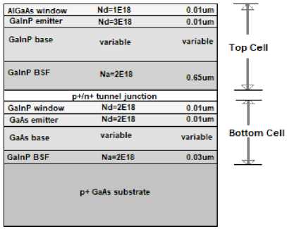
Fig.1. Schematic of the Multijunction Tandem Cell
Table 1. Summary of the results for the Optimized Cell at 25ºC
|
Cell/ Characteristics |
V OC (Volts) |
I SC (Amps/cm 2 ) |
FF |
ɳ |
|
Top Cell |
1.3450 |
0.0136 |
0.8856 |
0.0162 |
|
Bottom Cell |
0.9546 |
0.0136 |
0.8627 |
0.0112 |
|
Tandem Cell |
2.2996 |
0.0136 |
0.8761 |
0.0274 |

Fig.2. (a) I-V Characteristics (b) P-V Characteristics (25ºC)
-
3.1. Effect of Temperature
After the optimization of the solar cell, the effect of temperature on the top and the bottom cells were independently analyzed. The operating temperature was varied from 25ºC to 100ºC with a device area of 1cm2. The simulations were performed under AM1.5G one sun illumination. The temperature dependence of the material parameters for GaInP and GaAs were taken into consideration before the simulations were performed [13,14]. The objective was to identify the dependence of the performance of the tandem cell for each of the electrical parameters already described.
The temperature dependence of bandgap in semiconductors can be described by [15]:
E TA = E (0) - OT— (6)
g ( ) g( ) (T+в) ()
Where
E g (T) is the bandgap at a particular temperature
E g (0) is the bandgap at 0K
α and β are constants for a particular semiconductor.
The temperature dependence of V OC can be calculated from equation (2) as:
dVOC dT
-
V^ KT f dJ dJ„ )
OC SC 0
An expression for the FF without considering the resistive losses is given as [11]:
FF =
v oc - ln ( voc + 0.72 )
voc
+1
where voc is the normalized value of VOC with respect to the thermal voltage.
The variation of the FF with temperature is governed by the equation (8) which can be derived from equation (7):
OC OC
^~
-o^ - 0.28
- FF
v
10^ + 0.72 KT
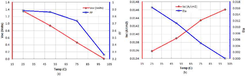
Fig.3. (a) VOC and FF (b) I SC and ɳ fort Different Temperatures (Top Cell)
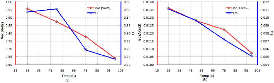
Fig.4. (a) VOC and FF (b) I SC and ɳ fort Different Temperatures (Bottom Cell)
The Fig.3(a) and 4(a) indicates that the VOC decreases almost linearly for the top and the bottom cells. This decrease in VOC is because of the increase in the dark current density in the cells and is governed by the term J0 in the equation (7). The increase in the value of the dark current is primarily due to the temperature dependence of the intrinsic carrier concentration (n i ) in the cell as evident from the equation (3). The V OC decreases by 17.3 and 4.27mV/ºC rise in temperature for the top and the bottom cells respectively. Also the FF in general decreases for both the top and the bottom cell with increasing temperature because of the decrease in V OC . However, there is an increase in the FF in the bottom cell from 25 to 50ºC. This variation in the FF can be attributed to its independence on the I SC for the case of the top cell and to its dependence on I 0 for the bottom cell (25ºC-50 ºC). The anomaly in the nature of the FF curve (increasing) in the temperature range of 25 ºC-50ºC can be described in terms of its dependence on the reverse saturation current (J0). This may be attributed to the fact that with the increase in temperature the intrinsic carrier concentration (ni) decreases because of increased recombination of the excess charge carriers. This results in a decreased value of J0 and increase in the FF. At temperatures over 50ºC, the generation rate exceeds the recombination rate resulting in the expected decrease in the FF curve. The FF decreases by 0.83% and 0.16%/ºC rise in temperature for the top and the bottom cell respectively.^
The I SC increases for the bottom cell with an increase in the temperature, however for the bottom cell the I SC decreases with the increase in temperature as apparent from the Fig.3(b) and 4(b) respectively. The reason for the increase in I SC for the top cell can be ascribed to the increase in the intrinsic carrier concentration at higher temperatures. In contrast for the bottom cell, the I SC decreases with the increase in temperature because of the higher doping concentration present in the base layer resulting in increased recombination of the excess charge carriers and lower collection probability at the terminals. For the top cell and the bottom cell the ISC increases and decreases by 0.013 and 0.038mA/ºC rise in temperature respectively. It can also be observed that the ɳ of the top and the bottom cell decreases with the increase in temperature. From equation (5) it can be observed that the efficiency depends on all the other electrical parameters in a solar cell. Therefore since the FF initially increases for the bottom cell and no similar trend is observed in ɳ, it can safely be concluded that the effect of the FF on the efficiency is insignificant. The efficiency decreases by 0.213% and 0.08%/ºC rise in temperature for the top and the bottom cell respectively. These results are summarised in Table 2.
Temp (С)
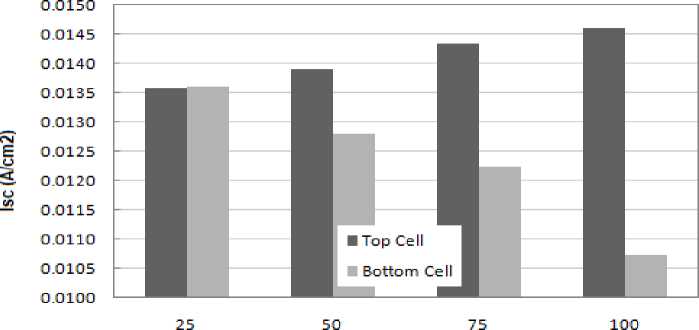
Fig.5. Difference in I SC of the top and the Bottom Cell at Different Temperatures
The Fig.5 emphasizes the results obtained after simulation suggesting that the short circuit current for top cell rises and for the bottom cell reduces with the increase in temperature with the difference getting progressively higher. It is also evident from the result presented in the Fig.5 that the current mismatch between the top and the bottom cell is greater at a higher temperature. It can also be noted that the variation in the current for the top cell is smaller compared to the variation in the current for the bottom cell. Therefore for the current match condition to be satisfied the tandem cell ISC is strongly dependent on the ISC value in case of the top cell.
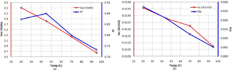
Fig.6. (a) VOC and FF (b) I SC and ɳ fort different temperatures (Tandem Cell)
For the tandem solar cell, the V OC is the sum of the open circuit voltages for the top and the bottom cells. Because the current equality criterion is to be fulfilled, the I SC is the short circuit current for the top or the bottom cell depending on whose value is lower. The efficiency of the tandem cell is simply the sum of the ɳ for the top and the bottom cells. The results obtained after simulation of the tandem solar cell is represented graphically in the Fig.6 (a) and (b).
Table 2. Variation of the Different Parameters with Respect to Temperature
|
Parameter variation /ºC rise in temperature |
∆V OC /∆T (mV/ºC) |
∆I SC /∆T (mA/ºC) |
FF (%) |
ɳ (%) |
|
Top cell |
-17.3 |
+0.013 |
-0.83 |
-0.213 |
|
Bottom cell |
-4.27 |
-0.038 |
-0.16 |
-0.08 |
|
Tandem cell |
-22.6 |
-0.027 |
-0.187 |
-0.293 |
|
Table 3. Performance of GaInP/GaAs tandem cell |
||||
|
Parameter |
V OC (Volts) |
I SC (mA/cm 2 ) |
FF (%) |
ɳ (%) |
|
25ºC |
2.3 |
13.6 |
87.3 |
27.3 |
|
100ºC |
0.6 |
10.7 |
73.3 |
5.1 |
|
Variation |
-73.9% |
-21.32% |
-16.03% |
-81.31% |
Table 3 indicates the variation in the parameters of the proposed GaInP/GaAs based tandem solar cell. It suggests that for the proposed structure the percentage variation in the open circuit voltage and the efficiency of the solar cell is significantly greater than the variation in the short-circuit current and the fill factor.
-
4. Conclusion
In this paper, investigations have been performed on a GaInP/GaAs based stacked series connected tandem solar cell. The effect of temperature (25ºC-100ºC) on each of the two cells has been studied independently to determine the performance of the resulting multijunction tandem solar cell. Studies have revealed that for the tandem cell the variation in the I SC is firmly dependent on the variation in I SC for the bottom cell. However, the performance of the tandem cell is majorly dependent on the performance of the top cell at higher temperatures. The increase in temperature results in a decrease in V OC , FF, and ɳ of the solar cell. For the proposed structure the I SC of the top cell and the bottom cell increase and decrease with temperature respectively. Because of the series connection, the efficiency of the tandem solar cell is limited by the solar cell that registers the lower current.
References Studies on the performance of a GaInP/GaAs tandem solar cell at elevated temperatures
- Sleiman, Adam, and Mahieddine Emziane. "P/N/P Double-Junction GaAs/Ge Solar Cell Devices for PV and CPV." In Sustainability in Energy and Buildings, pp. 629-636. Springer Berlin Heidelberg, 2012.
- Emziane, M., and A. Sleiman. "Multi-junction solar cell designs." In 2011 IEEE GCC Conference and Exhibition (GCC).
- Yamaguchi M. Multi-junction solar cells and novel structures for solar cell applications. Physica E, 2002, 14(1): 84.
- King R R, Law D C, Edmondson K M, et al. 40% efficient metamorphic GaInP/GaInAs/Ge multijunction solar cells. Appl Phys Lett, 2007, 90: 183516.
- M. Bosi, C. Pelosi, “The Potential of III-V Semiconductors as Terrestrial Photovoltaic Devices”, Prog. Photovolt: Res. Appl, vol. 15, pp. 51-68, 2007.
- M. Yamaguchi, T. Takamoto, K. Araki, and N. Ekins-Daukes, “Multi-junction III-V solar cells: current status and future potentials,” Sol. Energy, vol. 79, pp. 78-85, 2005.
- F. Dimroth and S. Kurtz, “High-efficiency multijunction solar cells,” MRS Bull., vol. 32, pp. 230-235, 2007.
- S. Nann, K. Emery, Spectral effects on PV-device rating, Sol. Energy Mater. Sol. Cells. 27 (1992) 189–216. doi:10.1016/0927-0248(92)90083-2.
- S. Yoon, V. Garboushian, Reduced temperature dependence of high-concentration photovoltaic solar cell open-circuit voltage (Voc) at high concentration levels, Proc. 1994 IEEE 1st World Conf. Photovolt. Energy Convers. - WCPEC (A Jt. Conf. PVSC, PVSEC PSEC). 90505 (1994) 1500– 1504.
- J.J. Wysocki, P. Rappaport, Effect of temperature on photovoltaic solar energy conversion, J. Appl. Phys. 31 (1960) 571–578.
- M.A. Green, Solar cells: operating principles, technology, and system applications, Prentice-Hall, Englewood Cliffs, NJ, 1982.
- Geoffrey A. Landis, Danielle Merritt, Ryne P. Raffaelle, and David Scheiman, “High temperature solar cell development,” 18th Space Photovoltaic Research and Technology Conference, 2005, pp. 108-115.
- A. Mc. Evoy, T. Markvart, L. Castaner, Practical Handbook of Photovoltaics Fundamentals and Applications, Second Edition, Elsevier Ltd, 2012.
- P. Basmaji, M. Guittard, A. Rudra, J.F. Carlin, P. Gibart, “GaAs tunnel junction grown by metalorganic vapor-phase epitaxy for multigap cascade Solar cells”, Journal of Applied Physics, vol. 62, pp. 2103-2106, 1987.
- Y.P. Varshni, Temperature dependence of the energy gap in semiconductors, Physica 34 (1967) 149–154.
