Study of heat transfer in the original design of electric heaters used for technological operations in the manufacturing of parts from VT6 alloy

Author: Stepanenko N.Yu., Stepanenko A.D., Demchenko M.V., Kim K.V.
Journal: Nanotechnologies in Construction: A Scientific Internet-Journal @nanobuild-en
Section: The results of the specialists’ and scientists’ researches
Article in issue: 5 Vol.17, 2025.
Free access
Introduction. This paper examines the original design of a high-temperature tubular electric heater cartridge designed for heating industrial tooling used in the production of VT6 alloy parts. The process requires maintaining stable high temperatures exceeding 1000 °C. Without proper heat treatment after welding, cracks form in the components, which can lead to subsequent failure. This becomes especially critical when the structure of the weld and base metal is highly heterogeneous, ranging from nanoscale to coarse-grained. Furthermore, undesirable thermal effects on tooling components require additional costs for cooling and monitoring. The aim of the research is to evaluate the heat transfer of the original design of electric heaters used in the production of parts from VT6 alloy. Methods and Materials. The heat transfer study of the proposed heater design was performed using the finite element method in the Ansys software package, using the Transient Thermal calculation module. To validate the calculated values, a test rig was developed that reproduced the simulation results. A qualitative analysis of the temperature fields confirmed the hypothesis of uniform operation of the proposed heater design. Results and discussion. A quantitative analysis reflected the heating conditions of the VT6 alloy. The temperature modeling results at tooling control points were experimentally confirmed, ensuring that the target temperature of 1000 °C was achieved in a localized zone. The error was ± ≈ 70 °C. The microstructure of VT6 titanium alloy samples was examined in various zones after heat treatment. Conclusion. Based on the conducted research, recommendations are proposed for selecting optimal operating conditions for high-temperature tubular electric cartridge heaters of this design, and their potential applications are described.
Tubular heating element, titanium alloy VT6, modeling, finite element analysis, nanostructure
Short address: https://sciup.org/142246080
IDR: 142246080 | DOI: 10.15828/2075-8545-2025-17-5-609-617
Text of the scientific article Study of heat transfer in the original design of electric heaters used for technological operations in the manufacturing of parts from VT6 alloy
Original article
Степаненко Н.Ю., Степаненко А.Д., Демченко М.В., Ким К.В. Исследование теплопередачи оригинальной конструкции электронагревателей, применяемых для технологических операций изготовления деталей из сплава ВТ6. Нанотехнологии в строительстве. 2025;17(5):609–617. – EDN: IRXSFB.
The most common and widely used source of electrical heat for industial applications is the tubular electric heater (TEH). A distinctive feature of cartridge or finger electric heaters (Electric Cartridge Tubular Heaters) is the ability to create a significant heat flow from their surface. They are used in thermal forming machines, for welding, soldering, or attaching to tanks and pipes, as well as in heated molds, combined air/liquid heaters, and furnaces. Tubular electric heaters have the following operating characteristics: voltage from 12 V to 380 V, power from 100 W
to 25 kW, temperature up to 1200 °C depending on the sheath material, diameter from 6 mm to 22 mm (nonstandard diameters are possible), and length from a few centimeters to several meters.
In order to improve the performance characteristics of tubular heaters, various design techniques are used in known technical solutions that facilitate an increase in heat transfer without increasing energy costs: a heater body of a special shape or with external ribbing, for example, a metal strip, ribs, a spiral, plates [1–8], a body with double walls, the gap between which is filled with a substance that ensures the maintenance of a given
THE RESULTS OF THE SPECIALISTS’ AND SCIENTISTS’ RESEARCHES temperature (the use of two layers of insulating materials facilitates operation at high voltage, quartz [3], copper [4], polytetrafluoroethylene or polyetheretherketone and a metal sleeve [6, 7] are used as the material for the internal element of the body), heating elements of various shapes (double spiral, flat spiral), made of various materials with high specific resistance, placed in a different environment [9–14]. Achieving the desired resistance requires a small heating wire diameter or a significant coil length. Reducing the diameter of the heating wire reduces corrosion resistance and increases the surface load required for efficient thermal energy emission. Scaling up the coil length increases cost and creates packaging issues. In [14], coils with an insulating oxide film on the surface were used. In [13], a wave-shaped electric heating element was proposed. The stretchable element can effectively reduce and absorb the mechanical load caused by alternating thermal stress through deformation.
Many cartridge heaters fail due to poor connections between the heating coil and the contact pins. In [15], electrical contact between the electric heating element and the power cable conductors is achieved through a connecting pin. In [16], the cartridge-type electric heater uses short strips of conductive tape to connect the ends of the heating coil to the contact pins.
The key parameter when calculating the heating element (coil) size is the specific power. The specific power of the element will determine the temperature of the heater shell and the temperature of the coil. Several factors must be considered when determining the optimal specific power. Overheating the surface can be unacceptable for many materials, as this can lead to deformation or melting. Since gases, including air, are poor conductors of heat, it’s important to ensure effective heat dissipation from the heater housing surface. This will help prevent overheating when operating at rated power, which can degrade the tubular heater’s thermal conductivity and shorten its service life. If the heating element is used in an aggressive environment, its housing may oxidize or become coated with a coating, reducing its efficiency. The resistance tolerance is also important. According to GOST 13268-83 [17], the power deviation at the operating temperature should be no more than plus 5% minus 10% of the nominal power for heating elements with an active resistance over 10 ohms and ± 10% for heating elements with an active resistance of 10 ohms or less. When selecting the appropriate specific power, the following factors are taken into account: overheating of the surface can cause deformation or melting of materials; it is necessary to ensure sufficient heat dissipation from the surface of the heater housing (gases, including air, are poor conductors of heat); an aggressive environment leads to oxidation or plaque formation on the housing.
The proposed technology and device, which incorporate tubular heaters, eliminate the need for standard furnace heat treatment (FHT) in the production cycle of large-scale metal structures in an electric furnace, as it allows for the targeted reduction of residual mechanical stresses in the metal that arise during manufacturing operations. For example, during welding, deformations arising in the metal are associated with the heterogeneity of the forming structure in the weld-affected zone [18, 19]. For titanium alloys, rapid cooling results in the formation of a finely dispersed structure within a narrow weld zone, with average plate thicknesses reaching into the nanoscale range [20]. Meanwhile, the original coarse-grained structure is retained around the weld. Due to the heterogeneity of the structure, the deformation magnitude can exceed maximum permissible values and, without proper heat treatment, lead to crack formation and subsequent failure of the structure. This also creates the problem of undesirable thermal effects on tooling components, requiring additional costs for their cooling and control.
The aim of the study is to evaluate the heat transfer of the original design of electric heaters used for technological operations in the manufacture of parts from VT6 alloy.
MATERIAL AND METHODS
The research portion of the study was performed on VT6 alloy specimens (GOST 19807-91) measuring 135× 60×15 mm (Fig. 1). VT6 alloy is a typical representative of the class of two-phase titanium alloys, and the results obtained on it can be applied with a reasonable degree of certainty to other alloys.
The initial microstructure of the VT6 alloy is shown in Fig. 2. The microstructure is of a mixed type, consisting of equiaxed grains of the α-phase and transformed lamellar β-phase. The volume fraction of the α-phase is 7±1%, and the grain size of the α-phase is 3±0.5 µm.
Microsections were prepared for metallographic studies. The microsections were cut from three zones of the
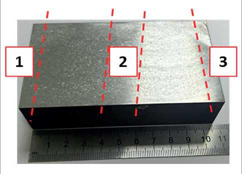
Fig. 1. External appearance of a sample made of VT6 alloy and the area of cutting into microsections
THE RESULTS OF THE SPECIALISTS’ AND SCIENTISTS’ RESEARCHES
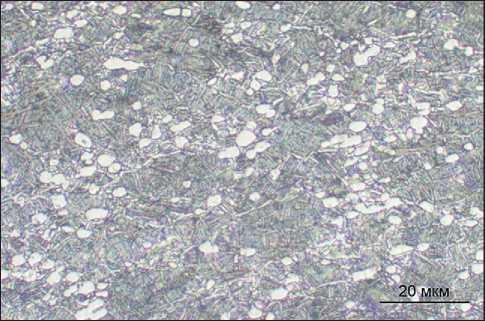
Fig. 2. Microstructure of VT6 alloy in as-delivered condition
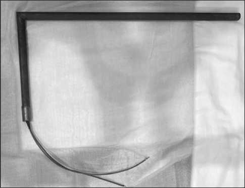
Fig. 3. Tubular heater of the proposed design
titanium alloy sample in accordance with Fig. 1. Etching to reveal the structure of the VT6 alloy samples was carried out chemically in an aqueous solution of hydrofluoric and nitric acids for 10-15 seconds using the dipping method [21]. The microstructure was examined using an Olympus GX51 optical microscope.
A pair of tubular heaters with single-ended currentcarrying contacts of an L-shaped design, each rated at 1390 W, was used in the study (Fig. 3). The heater body is made of 12KH18N10T steel, the coil is made of KX23YU5T alloy, and the filler is NB boron nitride powder.
A distinctive feature of the proposed design is its angular shape. The length of the unheated areas at the ends of the heated leg is determined by the length of the current-carrying contacts. The length of the unheated leg is determined based on the dimensions of the tooling and the design of the tooling and equipment in which the heaters are installed. The cross-section of the resistive heating element is determined based on the specific power rating of the material under the given operating conditions. The current-carrying contacts are angled rods. The heater body is welded and consists of two parts. This allows the current-carrying elements to be placed in the cooling zone, where they will not heat up. The currentcarrying contacts are insulated at the junction with the electrical wires using a high-temperature sealant. This protects against moisture absorption and loss of the dielectric heat-conducting material.
The finite element method (FEM) is used to model the heat treatment process. To study the transient heat transfer from tubular heaters to the fixture and then to the sample, it is advisable to use the transient thermal analysis (TTA) method.
At the modeling stage, the properties of the materials of the test bench elements were specified, and a grid of a three-dimensional model of the installation was constructed (Fig. 4).
The boundary conditions were set for the heat flux for each tubular heater (indicated by blue arrows on the
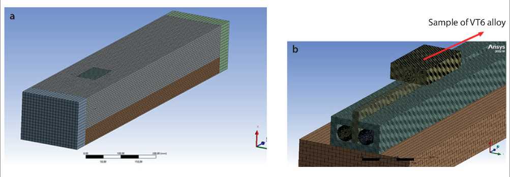
Fig. 4. Three-dimensional model of the contact heat treatment unit for a VT6 alloy sample: a – general view; b – view without the top thermal insulation coating
THE RESULTS OF THE SPECIALISTS’ AND SCIENTISTS’ RESEARCHES inner surface of the heater housings in Fig. 5a), as well as the solver parameters (process duration). The process parameters (temperatures in different parts of the sample) were recorded on four surfaces: the top of copper plate No. 4, the center of the bottom of sample No.1, the center of sample No. 2, and the upper right corner of sample No. 3 (indicated by numbers in Fig. 5b).
To validate the calculations performed using the ANSYS software package, a test rig for the thermal testing of a flat specimen was designed and manufactured (Fig. 6). It consists of an internal box measuring 827×80×45 cm, made of 12KH18N10T steel, containing electric heaters with a heated section length of 580 mm. A copper plate was positioned between the tubular heaters, transferring heat from the heating elements to a VT6 alloy specimen located above the heating elements. The entire structure was covered with thermal insulation material (thermal insulation boards at the base and ends; 20 mm thick fibrous thermal insulation covering material
(in two 40 mm thick layers) was used for the front and rear of the rig.
A VT6 alloy sample had 4 mm diameter holes drilled into them, with three thermocouples (No. 1–3) attached at the edges and in the center (Fig. 6). Thermocouple No. 4 was attached to a copper plate. A reference thermocouple was mounted on the surface of one of the heaters. Four thermostats were installed in the lower section, one of which controlled the heating process, while the other three read the temperature of the reference thermocouples. The thermocouple and heater temperatures were recorded in the SCADA system.
The measurement error of the thermostat is ±0.5% (range from –200 to +1300 °C).
RESULTS
Fig. 7a shows the results of the temperature field simulation, and Fig. 7b shows the heat flow distribution.
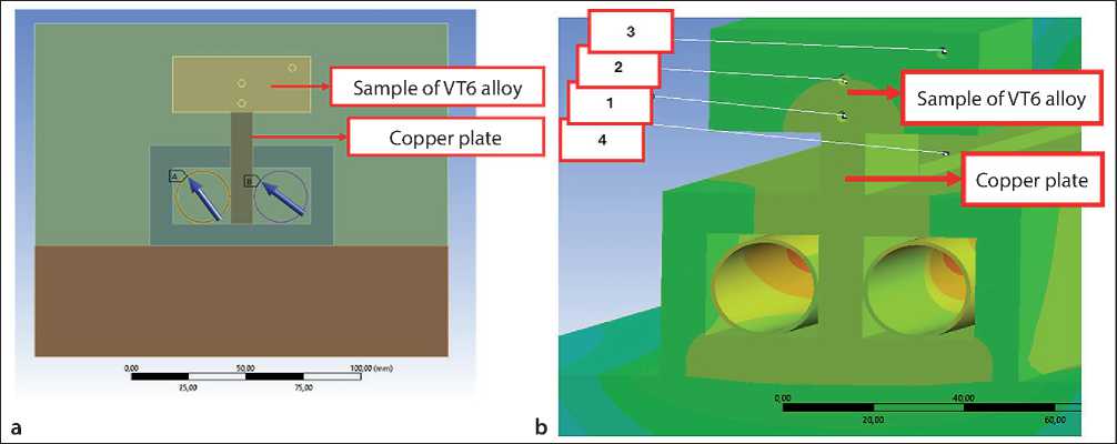
Fig. 5. Boundary conditions: a – control points; b – heat flow assignment
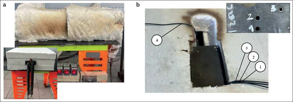
Fig. 6. Test rig: a – general view of the rig; b – location of holes in the sample for thermocouples
THE RESULTS OF THE SPECIALISTS’ AND SCIENTISTS’ RESEARCHES
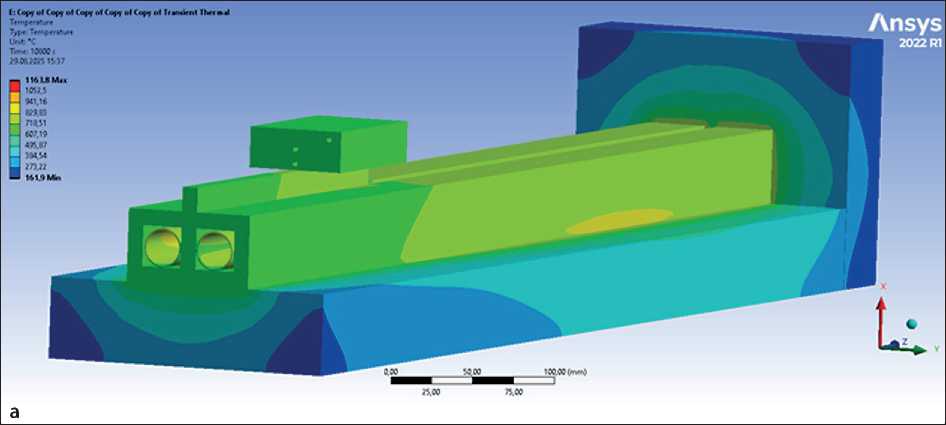
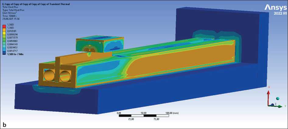
Fig. 7. Distribution map (view without covering thermal insulation): a – temperature fields, °C; b – heat flow, W/mm2
The maximum temperature recorded on the heater surface was 1164 °C. A qualitative analysis of the temperature distribution and heat flow maps demonstrates the uniformity of operation of the proposed heater design. The long leg contains the resistive heating element and is heated, while the short leg allows the current-carrying wires to be routed away from the hot zone of the heated fixture.
The results of modeling and experimental study of temperatures at four control points are presented in Fig. 8.
Heating mode simulation in Ansys demonstrated uniform linear heating at all studied points of the VT6 alloy specimen. The maximum experimental heating temperature was Theat = 972 °C at thermocouple No. 4 (copper plate) with a heating time of t = 180 minutes. The difference between the experimental temperature values on the copper plate (thermocouple No. 4) and the calculated value (No. 4_Ansys) indicates assumptions in the modeling of this material. The maximum temperature on the surface of the VT6 alloy specimen was recorded by thermocouple No. 1: Theat = 685 °C. In the central part of the specimen, the temperature was recorded by thermocouple No. 2 and amounted to T = 648 °C. The lowest heating temperature was recorded by thermocouple No. 3 in the upper right corner of the specimen: Theat = 604 °C.
Heating at all points of the VT6 alloy sample is uniform. The experimental temperature is approximately 70 °C lower than the theoretical value, which is explained by the properties of the porous dielectric [22], which were not taken into account in the modeling.
The results of a study of the VT6 alloy microstructure after heat treatment in various zones are shown in Fig. 9. The maximum temperature on the sample surface, as noted above, was 685 °C, which is significantly lower than
THE RESULTS OF THE SPECIALISTS’ AND SCIENTISTS’ RESEARCHES
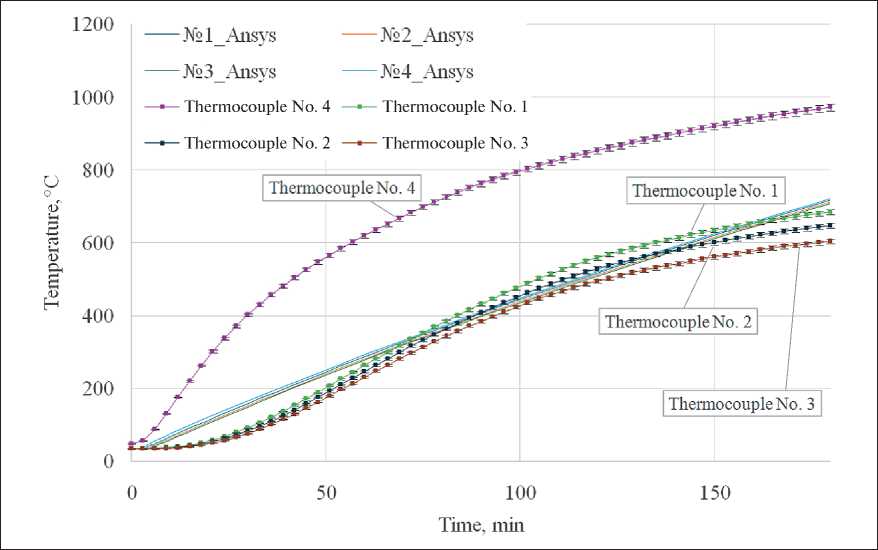
Fig. 8. Graphs of calculated and experimental temperature values in four measuring thermocouples
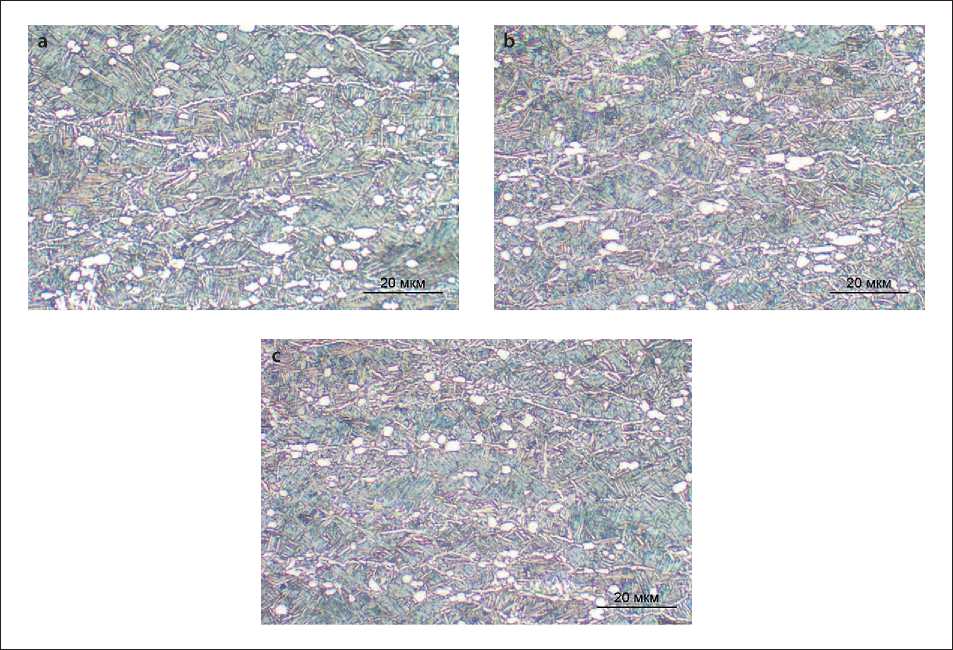
Fig. 9. Microstructure of VT6 alloy: a – zone 1; b – zone 2; c – zone 3
THE RESULTS OF THE SPECIALISTS’ AND SCIENTISTS’ RESEARCHES the onset temperature of the polymorphic transformation for the VT6 titanium alloy. No significant changes occur upon heating to this temperature (Fig. 9), which is confirmed by the results of quantitative metallography (Table 1). The structure remains mixed and is uniform in all zones of the sample, confirming the uniformity of heating.
Thus, the implementation of this localized heat treatment technology and the design of heaters and tooling in the production process will reduce the risk of defects by improving their quality, which is especially important for large-scale structures. This ensures more uniform heat distribution and reduces the likelihood of metal overheating, thereby ensuring the required product strength by minimizing unwanted changes in the material’s structure.
It is worth suggesting that this thermal treatment technology may be of interest as a post-processing option for welded joints in components produced by deformation welding. When joining components made of two-phase titanium alloys using linear friction welding, a narrow zone of the formed weld undergoes phase transformations due to subsequent accelerated cooling, forming a finely dispersed martensitic αʹ structure. The thickness of the αʹ-phase plates can reach the nanoscale range [23, 24,
-
25] . To achieve a uniform structure throughout the entire volume of the joined components, the implementation of the local technology described in this paper is particularly relevant.
CONCLUSION
-
1. The results of heat flow simulation made it possible to evaluate the heat transfer efficiency of the design of the equipment, which allows simulating the desired result of the heat treatment process;
-
2. Experimental studies on a test bench confirmed the hypothesis of uniform heating by the proposed design of the heating element during heat treatment of a sample made of titanium alloy (convergence of about 2% relative to the target temperature after the expected time has passed).
-
3. The results of a metallographic study of a VT6 alloy sample confirmed the uniform heating of the proposed heating element design.
The proposed thermal treatment technology and tubular electric heater design may be of interest for localized heating of industrial equipment used to manufacture VT6 alloy parts.
