
Study of the flow characteristics of a shut-off and control device for generating a controlled gas flow
Журнал: Nanotechnologies in Construction: A Scientific Internet-Journal @nanobuild-en
Рубрика: System solutions for technological problems
Статья в выпуске: 5 Vol.18, 2026 года.
Бесплатный доступ
Introduction. Industrial pipeline valves are among the most important elements of energy metering, both within common gas distribution systems and as a precision control element directly acting on an actuator or mechanism. The most specific requirements apply to shut-off and control devices (SCDs) used in high-risk industries, as well as in precision high-tech critical manufacturing. The ability to change and regulate the flow characteristic, as well as the response time of the element separating the two parts of the communicating system, play a significant role. The use of SCDs to shape an inert gas flow, according to the established law, is a key requirement for actuators in systems for manufacturing parts (the material of which is, as a rule, in a nanostructured state) using superplastic forming (SPF). The requirements for the actuator of a gas distribution system to perform the SPF operation are determined by a graph based on the part geometry. A bellows shut-off needle valve is adopted as the actuator unit, as it is optimal in design due to the seal used, as well as a metering needle that allows changing the flow cross-section of the channel. Methods and Materials. Modeling and finite element (FE) analysis to determine the flow characteristics of a bellows shut-off needle valve in a gas distribution system were performed using a specialized software package for scenarios of control rod handle rotation at 10°, 45°, and 90°, taking into account the required boundary conditions. Full-scale tests to verify the finite element method (FEM) calculations were carried out on a test bench using a bellows shut-off needle valve with the required parameters of the test bench elements. Results and Discussion. The article presents the results of finite element analysis (FE) and full-scale bench tests to verify the modeling results. The research revealed that the dependence of the working fluid flow rate on the angle of rotation of the control rod handle is not linear. In the range of handle rotation angles from 0° to 40°, a stable increase in flow rate is observed. With a further increase in the handle opening angle from 40° to 60°, the nature of the change in the working fluid flow rate changes. Abrupt changes are observed, which can be explained by a relatively large opening of the housing seat. This leads to phenomena (stalls, flow swirls, etc.), causing flow rate fluctuations. After reaching a rotation angle of 60°, the flow rate graph becomes oscillatory. In this section, the flow is constantly exposed to significant turbulent phenomena and becomes unstable, which complicates the accurate determination of the working fluid flow rate. Conclusion. A combination of finite element modeling and a full-scale experiment allowed us to verify the flow characteristic obtained through FEM calculations in a specialized software package with data from full-scale bench tests of a bellows-sealed shut-off needle valve. The discrepancy between the FE analysis results and those obtained during full-scale tests is within 5%, allowing the method described in this article to be used to obtain sufficiently accurate and reliable results.
Короткий адрес: https://sciup.org/142249024
IDS: 142249024 | DOI: 10.15828/2075-8545-2026-18-5-701-712
Текст научной статьи Study of the flow characteristics of a shut-off and control device for generating a controlled gas flow
Original article
Степаненко Н.Ю., Чертовских С.В., Рубцов А.В., Иванов Н.Е. Исследование расходной характеристики запорно-регулирующего устройства для формирования управляемого потока газа. Нанотехнологии в строительстве. 2026;18(5):701–712. – EDN: EPTGEW.
Shut-off and control valves (SCVs) play a vital role in many industrial processes. The safety and quality of the processes in which they are used depend on the characteristics and precision of their operation. Commonly used in industry are dampers, gate valves, ball valves, and other types of shut-off valves. These valves have a relatively simple design, but they have a short service life under continuous, high-cycle conditions and lack the ability to smoothly regulate flow. Various types of pressure valves and regulators are among the most suitable for smooth control. Compared to shut-off valves, these devices have a more complex design and are less suitable for complete flow shut-off due to their poorer sealing properties due to their specific design.
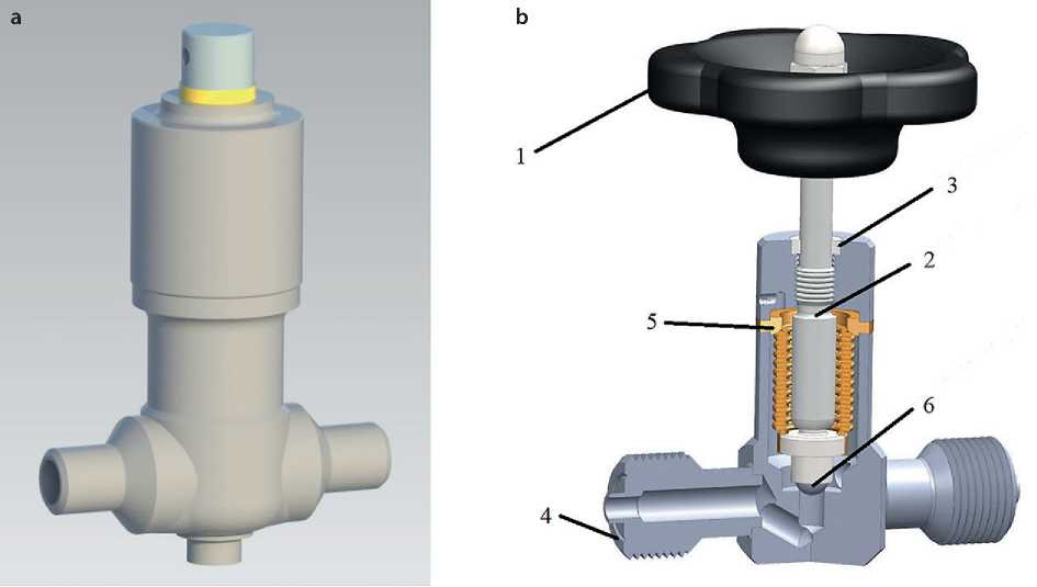
One type of shut-off switchgear is the bellows-type shut-off needle valve (Fig. 1). It is a high-tech device designed for precise regulation and hermetically sealed shut-off of the flow of the working medium in various engineering systems [1–3].
Thanks to its special design, this valve can operate under high pressure and temperature conditions, which can be harsh on common industrial materials. These advantages allow these valves to be used in various gas distribution systems, including as part of the SPF process complex for the process of forming parts, the material of which, as a rule, is in a nanostructured state.
The valve consists of a handle 1, which is connected to a control stem 2, at the end of which is a metering needle 6, a stainless steel body 3, gas line connections 4, and a metal bellows 5.
When the handle 1 is rotated, the control rod 2 moves along the thread of the body 3. When the valve is closed, the control rod 2 moves downwards and thereby inserts the metering needle 6 into the seat located in the body 3. This seals the channels connecting the connection points of the gas main. When the valve is opened, the control rod 2 rises, removing the metering needle 6 from the seat. In this case, the metering needle 6 and the seat of the body 3 are designed in such a way that when the metering needle 6 is raised, the flow between the channels occurs along a variable cross-section, adjusted depending on the height of the metering needle 6. Bellows 5, connected to the body 3 and the control rod 2, is necessary to ensure the tightness of the valve body and protect the control rod 2 from the effects of the working medium on it [4–5].
In many technological processes, the control of bellows valves is automated using various devices (e.g., servo drives), which allows for increased speed and accuracy of process control. The initial parameter for writing a control program for valve operation corresponding to the technological process is the flow characteristic (the dependence of its flow area on the angle of rotation of the control rod). The flow characteristic is also necessary to ensure the quality of a large number of technological processes
а
b
Fig. 1. Bellows shut-off needle valve: 1 – handle; 2 – control stem; 3 – body; 4 – gas line connections; 5 – bellows; 6 – metering needle; a) – 3D model; b) – design
Nanotechnologies in construction
Нанотехнологии в строительстве
2026; 18 (5): 701–712
Nanob
SYSTEM SOLUTIONS FOR TECHNOLOGICAL PROBLEMS
[1–3, 6]. Thus, in the SPF operation, the quality of the manufactured part directly depends on the accuracy of the forming gas supply.
A current method for obtaining the flow characteristics of bellows valves is mathematical modeling of the working fluid flow in valves under various operating conditions. The study of mathematical modeling of bellows valve operation is driven by the need to improve the efficiency and accuracy of technological processes (e.g., SPF), as well as to reduce the costs of experimental research. Modeling allows for the prediction of valve flow characteristics, which subsequently makes it possible to optimize process parameters [7–8].
Thus, the aim of this work is to model (with the implementation of FE analysis) the flow characteristics of a bellows valve in various operating modes with verification of calculations using bench tests.
METHODS AND MATERIALS
The FE analysis portion of the study was conducted using a specialized software package.
To calculate the flow characteristics, a model of a bellows-sealed needle valve section was used, consisting of: – the working fluid inlet section;
– the metering needle and body seat, which regulate the valve flow area;
– the working fluid outlet section.
The position of the metering needle relative to the body seat (i.e., the height of the metering needle’s lift from the seat) corresponds to the n-th angle of rotation of the valve handle. This lift is determined by converting the pitch of the body thread along which the control stem moves and the angle of rotation of the stem handle. The calculated air flow model is shown in Fig. 2.
The simulation was performed using the finite element method (FEM) using a specialized software package [2, 9–17]. To confirm the accuracy of the FEM analysis results, several calculations were performed using points obtained during the blowdown, specifically, rotating the control rod handle by 10°, 45°, and 90°.
The valve flow area between the metering needle and the body seat for various calculation options is shown in Fig. 3.
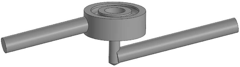
Fig. 2. Calculation model of air flow in a section of a bellows-type shut-off needle valve
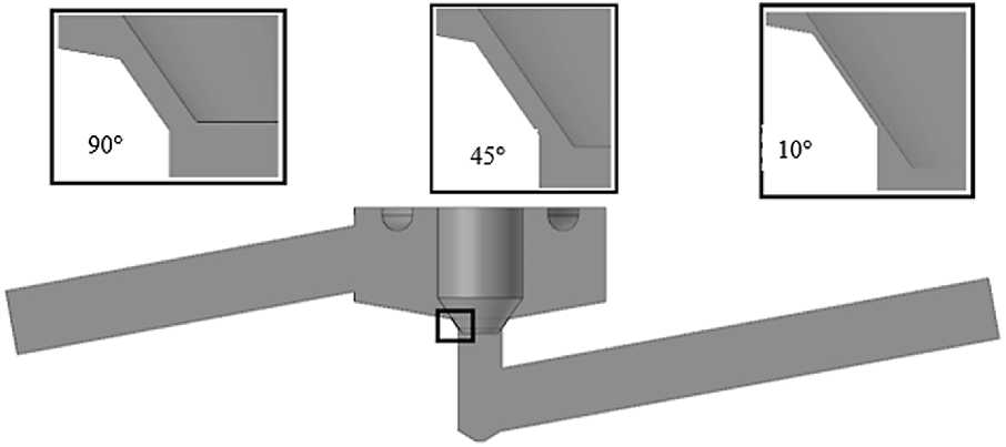
Fig. 3. Cross-section of the air flow model in a bellows shut-off valve when the handle is opened by 10º, 45º and 90º
Nanotechnologies in construction
Нанотехнологии в строительстве
2026; 18 (5): 701–712
Nanob
SYSTEM SOLUTIONS FOR TECHNOLOGICAL PROBLEMS
The mesh model in all calculation variants has a finer mesh at the point where the working fluid passes between the metering needle and the body seat, as well as prismatic layers near the walls on long straight sections of the working fluid’s entry and exit from the valve. The mesh model for calculating air flow in a bellows shut-off needle valve, using the example of a variant with the handle opened by 10°, is shown in Fig. 4.
The boundary conditions for the calculation were:
– total pressure at the valve inlet – 1.42 MPa;
– free flow to the atmosphere – patm = 101325 Pa, Tatm =
15 °C;
– working fluid – air;
– turbulence model – k–ε.
The k–ε turbulence model was chosen because, in this problem, we are concerned not with losses in the wall air flow, but with the parameters of the main flow. This turbulence model has also been successfully applied in numerous studies of hydraulic flow characteristics [9, 18]. The computational model with boundary conditions is shown in Fig. 5.
Full-scale tests to verify the FEM calculations were conducted on a test bench using a bellows-sealed shut-off needle valve, the design of which is shown in Figure 1b. The technical characteristics of the test valve are presented in Table 1.
The stand for determining the flow characteristics of the valve is an installation, the diagram of which is shown in Fig. 6 [2, 12].
In this case, the device supplying the working fluid (air) is a compressor with a large-volume receiver. Using a preset pattern, the operator rotates the flow regulator
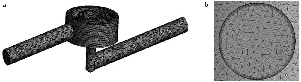
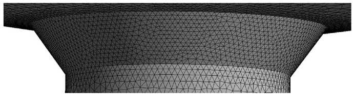
Fig. 4. A grid model for calculating air flow in a bellows-type shut-off needle valve, using the example of a handle opening of 10°: a) – mesh model of air flow in a bellows shut-off needle valve; b) – prismatic layers in the section of the inlet/outlet of the working medium in the mesh model; c) – the result of mesh refinement in the place where the working medium passes between the metering needle and the body seat
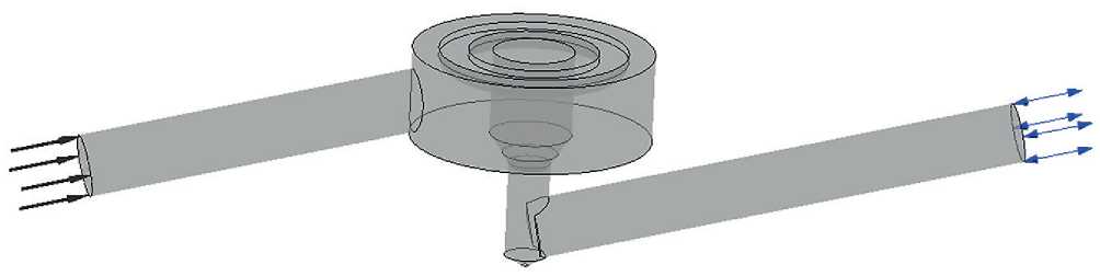
Fig. 5. Calculation model with boundary conditions
Nanotechnologies in construction
Нанотехнологии в строительстве
2026; 18 (5): 701–712
Nanob
SYSTEM SOLUTIONS FOR TECHNOLOGICAL PROBLEMS

Table 1. Technical characteristics of the tested valve
|
Parameter |
Value |
|
Nominal diameter, DN, mm |
10 |
|
Working fluid temperature, °C, max |
350 |
|
Working fluid pressure, MPa, max |
20 |
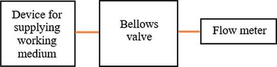
Fig. 6. Diagram of the stand for determining flow characteristics
of the bellows-type shut-off needle valve to the required angle. A flow meter measures the flow of the working fluid at the valve outlet. The air is released into the atmosphere.
Parameters of the test bench components:
– the compressor supplies compressed air at a pressure of pвх = 1.42 MPa;
– the position template of the bellows shut-off needle valve flow regulator allows for precise setting of the angular position of the regulator handle in 5° incre-mentsl;
– the flow meter measures the flow rate of the working medium at the valve outlet with an accuracy of ±1%. Blowing on the stand was carried out according to the following law: turning the handle of the control rod in 5° increments and holding for one minute to equalize the flow indicators.
The error calculation was carried out using the relative error method, according to the following formula:
δ = ∆/ x ист.•100%, (1)
where ∆ – limits of permissible absolute error;
x – the value of the measured quantity at the input (output) of the measuring instrument.
RESULTS AND DISCUSSION
The results of determining the flow velocity vectors in the valve, as well as the results of the total pressure distribution in the valve cross-section (Pa) when the control rod handle is opened by 10°, 45°, and 90° during the FE analysis are presented in Fig. 7–12.
The obtained results show that, with a sufficiently large valve opening (45° and 90°), turbulent phenomena (swirl, flow mixing, etc.) arise and continue to grow, the impact of which on the flow significantly exceeds the impact of similar phenomena when the valve is opened by 10°. Subsequently, it is these phenomena that play a key role in the occurrence of pulsations in the flow rate of the working medium, shown in Fig. 13.
Table 2 shows the experimental data obtained as a result of bench tests of a bellows shut-off needle valve.
Based on the results obtained during the FE analysis, as well as the results of bench tests, the dependence of air flow on the angle of rotation of the handle of the control rod of the bellows shut-off needle valve was established, which is presented in the form of a graph in Fig. 13.
Analysis of the results obtained during the blowdown test shows that the flow rate of the working fluid is not linearly related to the valve handle angle. A steady increase in flow rate is observed over a range of handle angles from 0° to 40°. This indicates that, with a relatively small valve opening, the working fluid flows through the valve without significant disturbances.
As the handle opening angle increases further from 40° to 60°, the flow rate pattern changes. The graph shows abrupt changes, which can be explained by the relatively large opening of the valve seat. This leads to phenomena (flow stalls, turbulence, etc.), causing flow rate fluctuations on the graph [9].
After reaching a 60° rotation angle, the flow rate curve becomes oscillatory. In this section, the flow is constantly and significantly affected by turbulence and becomes unstable, making it difficult to accurately determine the air flow rate.
Table 3 provides a comparative analysis of the air flow rates obtained from the finite element analysis and from the results of full-scale rig tests.
Having analyzed the results presented in Table 3, we can conclude that the discrepancy between the air flow values obtained during the FEM calculation and during bench tests, depending on the value of the valve handle rotation angle, is no more than 5%, which confirms the required accuracy and correctness of the FEM analysis.
CONCLUSION
Based on the data obtained from the research conducted, the following main conclusions were formulated:
-
1. It has been shown that the design of the bellows shut-off needle valve allows it to be used as a high-quality shut-off switchgear in critical industries with high operating environment parameters (pressure, temperature and flow).
-
2. A rig test of the bellows valve was conducted, which resulted in its flow characteristic being determined. The test results revealed that, due to the geometry of the working channel, flow stalls and turbulence occur at large opening angles, leading to an oscillatory
Nanotechnologies in construction
Нанотехнологии в строительстве
2026; 18 (5): 701–712
Nanob
SYSTEM SOLUTIONS FOR TECHNOLOGICAL PROBLEMS
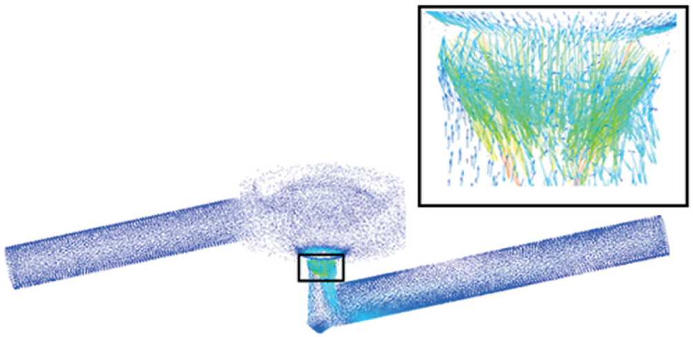
Fig. 7. Flow velocity vectors of the medium flowing through the valve when the control rod handle is opened by 10°
Total Pressure
Contour 1
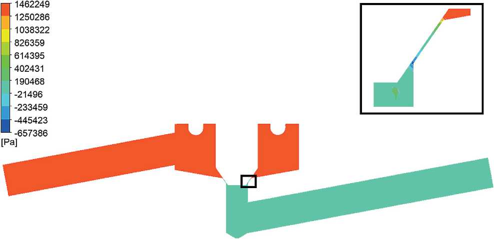
Fig. 8. Distribution of total pressure in the cross-section of the valve (Pa) when the control rod handle is opened by 10º
Nanotechnologies in construction
Нанотехнологии в строительстве
2026; 18 (5): 701–712
Nanob
SYSTEM SOLUTIONS FOR TECHNOLOGICAL PROBLEMS
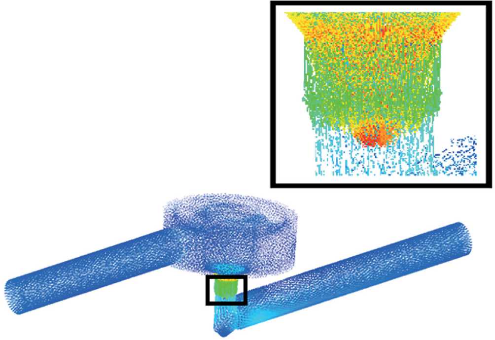
Fig. 9. Low velocity vectors of the medium flowing through the valve when the control rod handle is opened to 45°
Total Pressure
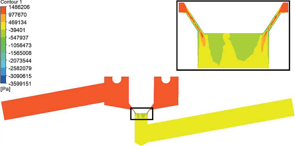
Fig. 10. Distribution of total pressure in the cross-section of the valve (Pa) when the control rod handle is opened by 45º
Nanotechnologies in construction
Нанотехнологии в строительстве
2026; 18 (5): 701–712
Nanob
SYSTEM SOLUTIONS FOR TECHNOLOGICAL PROBLEMS
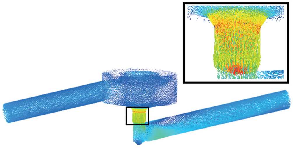
Fig. 11. Flow velocity vectors of the medium flowing through the valve when the control rod handle is opened to 90°
Total Pressure
Contour 1
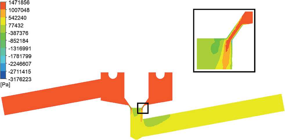
Fig. 12. Distribution of total pressure in the cross-section of the valve (Pa) when the control rod handle is opened by 90º
Nanotechnologies in construction
Нанотехнологии в строительстве
2026; 18 (5): 701–712
Nanob
SYSTEM SOLUTIONS FOR TECHNOLOGICAL PROBLEMS
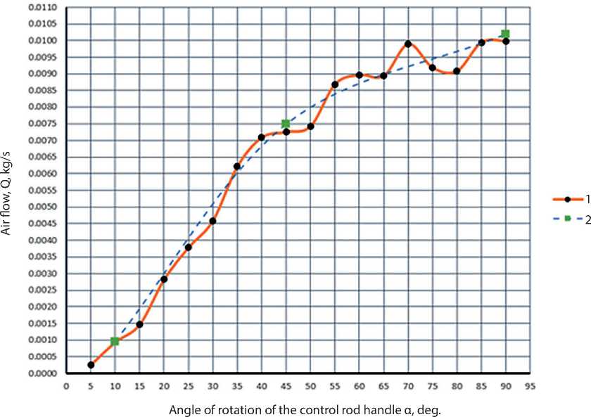
Fig. 13. Graph of air flow versus handle rotation angle of a bellows-sealed needle valve: 1 – experimental results; 2 – simulation results
Table 2. Experimental data obtained from bench tests of a bellows shut-off needle valve
|
Angle of rotation of the control rod handle α. deg. |
Air flow. Q. kg/s |
|
5 |
0.000255 |
|
10 |
0.000934 |
|
15 |
0.001468 |
|
20 |
0.002823 |
|
25 |
0.003778 |
|
30 |
0.004588 |
|
35 |
0.006216 |
|
40 |
0.007087 |
|
45 |
0.007250 |
|
50 |
0.007424 |
|
55 |
0.008687 |
|
60 |
0.008962 |
|
65 |
0.008936 |
|
70 |
0.009894 |
|
75 |
0.009180 |
|
80 |
0.009084 |
|
85 |
0.009949 |
|
90 |
0.009978 |
Nanotechnologies in construction
Нанотехнологии в строительстве
2026; 18 (5): 701–712
SYSTEM SOLUTIONS FOR TECHNOLOGICAL PROBLEMS
Nanob
flow characteristic after the valve’s control stem handle is opened more than 60°.
3. The FE method for analyzing the flow of the working medium in the valve allows us to determine the air flow through the valve at a certain opening angle of the control rod handle with an error of no more than 5% compared to full-scale tests on a bench.
Thus, data on the flow characteristics of bellows valves, obtained using mathematical modeling using the FE analysis method, will allow the creation of control programs for these valves for the required technological process, improving the quality of manufactured products and process safety, as well as minimizing the time of pilot testing of technological systems in which these valves are used.
Table 3. Comparative analysis of air flow values obtained from the results of the FE analysis, as well as from the results of full-scale tests on the stand
|
Calculation/ Parameter |
Airflow obtained as a result of FE analysis, Q, kg/s |
Airflow obtained as a result of full-scale tests, Q, kg/s |
Discrepancy between results obtained by FE analysis and full-scale tests, % |
|
Opening the valve handle by 10° |
0,96·10-3 |
0,93·10-3 |
3,2 |
|
Opening the valve handle by 45° |
7,49·10-3 |
7,25·10-3 |
3,3 |
|
Opening the valve handle by 90° |
10,2·10-3 |
9,98·10-3 |
2,2 |