Study on the Impact Breakup Model of the Space Target Based on the Thin Plate

Author: Weijie Wang, Huairong Shen, Yiyong Li
Journal: International Journal of Information Technology and Computer Science(IJITCS) @ijitcs
Article in issue: 2 Vol. 3, 2011.
Free access
In the paper, an engineering model for the im-pact breakup of the space target is studied based on the thin plate. The average fragment size model for the impact breakup of the thin plate is established depending on the strain rate, according as Poisson statistic fragments are discrete and distribution model is figured out. On the foundation of the constitution analysis for the target and projectile, the target equivalent model based on the thin plate is established, and projectile equivalent model is also given. The length and velocity degraded model are set up against the cylindrical projectile. The simulation case is analyzed and the result indicates that the paper model is effective, flexible and has important engineering reference value.
Space Target, Thin Plate, Impact Breakup model, Strain Rate, Projectile
Short address: https://sciup.org/15011616
IDR: 15011616
Text of the scientific article Study on the Impact Breakup Model of the Space Target Based on the Thin Plate
Published Online March 2011 in MECS
-
I. Introduction
With the increase of the space object (including active spacecraft and space debris) and development of kinetic energy weapon, the risk that space target encounters to be hypervelocity impacted is enhancing, e.g. the accidental collision between US and Russian satellite in 2009 [1], and the USA-193 deliberate space weapon test in 2008 [2], the fragment along with impact breakup of the space target has become the primary source and the collision breakup model also becomes a hotspot of study.
Since 1970s, a series of the impact breakup model has been established, namely historic model, Battelle breakup model, and US National Aeronautics and Space Administration standard collision breakup model (NASA model). Historically, the breakup models currently in use developed over a long period in time. One of the most fundamental works in this context is a publication by Bess originating from 1975 [3]. Many subsequent publications refer to this paper, partly modifying parameters of the model or introducing model extensions. The first version of the breakup model designated as “Battelle” model in this context was developed by a Battelle-led team under the European Space Operations Centre
-
* Corresponding author Address: Huairou 3380 mail box No.171 Beijing China, 101416.
(ESOC) contract between 1990 and 1993 in the wake of the observed disruption of the Spot 1 ARIANE 4 upper stage in November 1986 [4]. In 1998, NASA released a revised breakup model, which later has been implemented into the new version of NASA’s current space debris evolution model, EVOLVE 4.0 [5], and European Space Agency (ESA) further modified the NASA model in 2006 [6], thus, the NASA model acting as the representative of this field is widely used nowadays.
However, all of these models are experiential statistic, only a few of facts are taken into consideration, the spectrum of applicability is limited and couldn’t satisfy the demand of damage effect assessment for the impact of projectile on space target. The essence of hypervelocity impact breakup is the stress wave (including shock, plastic, elastic wave) which is induced by hypervelocity impact and diffusing both in the target and projectile, so the characteristic of space target impact breakup can be studied in terms of stress wave. The paper considers the realistic constitute characteristic both the target and projectile, the fragment average size model for the impact breakup of thin plate is established depending on strain rate, the fragments are discrete according to Poisson statistic and fragment distribution model is figured out, the target is equivalent to a system consisting with some thin plates; the length and velocity degraded model is set up against the cylindrical projectile; the typical case is simulated and analyzed in order to validate the effectiveness of the models. The simulation case indicates the related models established in the paper have important engineering reference value.
-
II. Breakup Model for Thin Plate
The plate that the stress and stain have not gradient distribution along the direction of plate thickness during impact body penetrating process is namely thin plate [7], the plate that its thickness is less than characteristic length of projectile is also called thin plate.
-
A. Impact Model of Projectile on Thin Plate
In the current model, only the case for cylindrical projectiles impacting at normal incidence on thin plate is considered. Fig. 1 shows the sketch map for the normal
Figure 1. Sketch map of projectile impact the thin plate
impact of projectile on thin plate, the body of projectile is cylindrical shape, the head of projectile takes on semi-sphere with radius of R , the P 0 is contacting face pressure during impacting instantaneously, the P' is hole wall pressure, the domain confined by hole radius r 0 is normal impact domain. Except for the normal impact domain, the stress wave in the thin plate plane induced by projectile hypervelocity impact can be regarded as cylinder wave, the intensity of stress wave decides the failure extent of the thin plate, according to the Ref. [7], when r0 < r < 2.21 r 0 , namely the domain confined by r is the large plastic distortion domain; when 2.21 r 0 < r < 3.64 r 0 , namely he domain confined by r 2 is the small plastic distortion domain; when r > 3.64 r 0 , thin plate occurs elastic distortion and doesn’t produce fragment. The domain confined by r 1 and r 2 is uniformly called no-normal impact domain.
A large number of penetration models, mostly empirical and some based on mechanics, have been developed for the prediction of hole-diameter in a thin target plate impacted by spherical projectiles at hypervelocity, for the cylindrical projectile, referencing these models to characterize the relationship between projectile radius and radius of hole. Most of these models are of the form [8]
p 1 p 2 p 3
r L- rP^L I I V l_ I V L
^ 1 I II I
R Ip t JI c t J I c p J
Where p p and p t are the projectile and target density respectively; cp and ct are projectile and target bulk sound speed respectively; vI is the impact velocity; Tt is the target thickness, namely the thickness of thin plate; p 1~ p 4 , C 1 and C 2 are all constant, different models have variant parameter specified in Table 1, in the paper , the Sawle model parameter is chosen. Note that all variable’s unit in the paper is international standard unit.
TABLE I.
P arameters of P enetration M odel
|
Model |
Model Parameter |
|||||
|
C 1 |
C 2 |
p 1 |
p 2 |
p 3 |
p 4 |
|
|
Maiden |
2.4 |
0.9 |
0 |
1 |
0 |
2/3 |
|
Sawle |
2.6 |
1 |
0.22 |
0.22 |
0 |
2/3 |
|
Hill |
3.309 |
0 |
0.022 |
0.298 |
0.033 |
0.359 |
|
Chant |
V2П |
1 |
0.5 |
0.5 |
0 |
1 |
-
B. Fragment Average Size Model
The failure mechanism of thin plate in hypervelocity impact can be classified into three kinds according to the strain rate magnitude, correspondingly for the breakup of thin plate, its average fragment size Lc (fragment size Lc will be defined below) can be depicted as the function of strain rate and determined in three different breakup regimes, these are [9]:
Failure model 1: facture toughness dominated failure (low strain rate)
। У24 K c Г v P t c t ^ J
(2-1)
Failure model 2: yield strength dominated failure (medium strain rate)
L c —

(2-2)
Failure model 3: surface tension dominated failure
(high strain rate)
L c —

(2-3)
Where K c is the target fracture toughness; s is the stain rate; Yt is the target yield strength, the stress which induces material such as aluminum alloy to take on 0.2% plastic strain is acted as yield index; у is the surface tension. Strictly, K c , Yt , and у are depending on material temperature as following.
t -'o n Y
TT 0
T -T I
Tm T O 7

T-T
TT 0

1 -
T m
Y — ^o

Where the variables with subscript “0” is the reference value; T is temperature, Tm is the melt temperature, Tc is critical temperature; nY , mY , nK and n a are constants, for the 7075-T6 aluminum alloy, these constants are 1.5, 0.02, -1 and 1.33 respectively. Considering the paper objective is to establish an engineering calculation model, so the material temperature influence on these variables is neglected.
Model 1 and 2 are fit for the breakup fragment of the material solid region, comparing with the Ref. [7]’s content, these fragments can be uniformly treated as the produce of material plastic distortion, Ref. [10] gives the transition equation between failure modes 1 and 2
& 0.003 p c,4 Y3
s ' = U К 4
Kc
According (3) K c , Yt are depending on material temperature, so it is very complex to calculate s,, and the temperature influence has been neglected, whereas if computing s t with the parameters of normal temperature, large error will be produced. Reference [10] thinks the transition between failure modes 1 and 2 occurs at strain rates of approximately 104s-1 for the aluminum, however if letting s t = 10 4 s1, in the instance of simulation case of Part V, namely impact velocity v , = 9000m/s , the radius of projectile R = 0.19m, calculating by (5), the max strain rate S = 7.1 x 10³s - 1, according to Ref. [10] in this circumstance, model 2 will fail, obviously this doesn’t match with the fact, by large calculation, letting the transition strain rate s, = 1.0 x 10³s - 1 in the paper.
Model 3 is fit for the fragment of the material liquid region, is used when material temperature is higher than its melting point. For the target and projectile consisting of aluminum alloy, when impact velocity is above 8km/s, the material will appear melting, taking the 7075-T6 aluminum alloy with the example, its surface tension Y = 1.188N/m , density p t = 2800kg/m3, the strain rate is commonly above 10 6 s - 1 when material is liquefied, according as these parameter, the average fragment size is on the order of 10 - 5m. Evidently, the risk of the fragment produced by model 3 to spacecraft is limited and the liquefied material is few part of the target through simulation analysis, so the paper doesn’t consider the fragment produced by model 3.
C. Solution Model of Strain Rate
Equation (2) indicates that average fragment size is the function of strain rate, the way to solve the strain rate is essential to calculate the average fragment size.
1. Solution Model for Normal Impact Domain
Normal impact domain suffers the effect of shock wave which is the discontinuous wave. Reference [10] considers the complexity of the shock wave diffuse and gives an engineering model to solve the strain rate
'
s,
d v d r
v
■ e = _ r
Where s r and se are the radial and hoop component of strain rate, so the strain rate s = s 2 +s g ; v is the radial particle velocity. It can be seen the way to calculate v is key to solve strain rate, whereas v depends on impact parameter.
When projectile impacts target, the initial pressure P0 can be acquired by conservation of mass and momentum. According to the one-dimensional shock wave theory [11], the initial conservation equations of mass and momentum for the thin plate are in the following form p,D, = p'(D, - v3 (7-1)
( p D , ) D , = [ p‘ ( D , - v ‘ )]( D , - v 3 + P (7-2)
Where v ‘ and p’ are the article velocity and density behind the shock wave; Dt is the velocity of shock wave in the target, according to Ref. [9], to first order, Dt can be replaced by bulk sound speed ct , considering the engineering applicability, the paper refers to this way, bringing (7-1) into (7-2), obtaining
P =p , c , v ' (8-1)
Likewise, for the projectile, there is
P =p p C p ( v, - v D (8-2)
Combining (8-1) and (8-2), expunging v ‘ , so
_ ppcpp,c, 10 vI p pcp +p,c,
Radial particle velocity v and initial pressure P 0 have following relationship [12]
v = ^ Pr ^y (10)
p , c ,r
Where r is the variable of the equation, consequently ,
s = fE — s 2 R
2 P0r0 sg , p ,С,Г
Where factor f . < 1 is used to fit experimental data, may be f . = 0.3 . For the strain rate of normal impact domain, the paper refers to this model.
-
2. Solution Model for No-Normal Impact Domain
No-normal impact domain suffers plastic wave effect to produce fragment, by the characteristic of cylinder wave, the strain rate of this domain can be solved. In the polar coordinate, the strain rate model of cylinder wave is
Therefore
2 P 0 r 0
r 3 .
p ,c,r
P 0 r 0 2 V r 4 + 4
p , C ,r 3
D. Fragment Distribution Model
The strain rate is continuous with r and needs to be dispersed into some bins, then the distribution characteristic of fragment is depicted by average fragment size of every bin, Ref. [9] regards the fragment distribution of single bin as Poisson statistic, the disposed fragment data is consistent with experimental data, the paper refers to Ref. [9] and processes the fragment discretely.
The strain rate is divided into N0 bins, the target mass of ith bin is mi , the fragment size is Li , the data is arranged in order of increasing average fragment size, so L < Li+1. According to the characteristic of the Poisson statistic, in ith bin, a probability distribution of finding a fragment of mass ц within a tolerance dц given by dP (ц) =1 e-цГц d ц (12)
Ц
Where ц is the mean value of the fragment mass in the bin. Integrating from 0 to ц and multiplying by the total mass m of the bin gives the cumulative mass of fragments of mass less than or equal to ц in the bin
M ( ц ) = m , [1 - e ] d ц (13)
There is certain relationship between fragment mass and size, Ref. [9] assumes that the mass of the fragment is related to the cube of the fragment size (such as for cubic or spherical particles), and establishes the relationship model in the following

However if given fragment size Lc , the fragment mass ц can be figured out only on condition that fragment is cubic or spherical, for the breakup fragment of the thin plate, except very small particles, most fragments will take on shape of sheet , actually NASA model also gives up the assumption that fragment is spherical and adopts the “characteristic length” to specify the fragment shape, the characteristic length is defined as the mean length of fragment three main axes as Fig. 2 shows.
Figure 2. Fragment characteristic length
Referring to the NASA model, the paper adopts the characteristic length or fragment size to characterize the shape of fragment, namely
x + y + z
L =-------. Meanwhile c3
by large calculations the following empirical equation is given to describe the relationship between size and mass against the fragment with the shape of sheet.
T ц = (T- + 0.1) L 3p t
L
For the fragments produced by same thin plate, assuming that (14) still satisfies (12).
Therefore, in the bin i , the cumulative mass of fragments having a size less than or equal to Li is
M (ц) = m , [1 - e "( Lc^ ]
Finally, the total cumulative mass of all fragments in all bins have a size less than or equal to Li is
N 0 3
M T ( L c ) = £ m , [1 - e ~( LjL‘) ] (17)
i = 1
The fragment mass distribution is given, actually the fragment number distribution can be figured out by substituting fragment population Ni for mi in (16) and (17), where the fragments population in the bin i is N , = m , /ц о The fragment population transition from average size to Poisson statistic is depicted in Fig. 3. Note that although the distribution is exponential in mass, it is exponential in the cube of the size leading to the character of the statistical distribution in Fig. 3(b).
-
III. Space Target and Projectile Model
In the paper, space target is orbiting satellite, therefore, modeling target is modeling satellite.
-
A. Target Characteristic Analysis
The mass of satellite mainly consists of three type of material: metal material, the representative is aluminum alloy, the density is about 2800kg/m3; composite material, the representative is Carbon Fiber Reinforced Plastics (CFRP), the density is 1760~1800kg/m3; propellant, the representative is hydrazine, the density is 1008kg/m3; The density of US spacecraft launched from 1987~1984 is between 20~172kg/m3, mean is 79 kg/m3. Reference [14] gives the relationship between satellite volume V and wet weight Mw (namely including propellant mass):
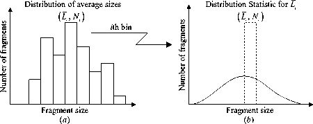
Figure 3. Fragment distribution transition
V = 0.01 M„
w
According to this equation, the density of satellite wet weight is only 100 kg/m3. In conclusion, there is large spacing inside the satellite. On the structure, satellite usually adapts cabin constitution [15], every cabin includes many faceplates. Fig. 4 shows a typical satellite model which is utilized in the hypervelocity impact test by NASA [16]. Reference [17] studies the damage effect for the hypervelocity impact of Projectile on the Tactical Ballistic Missile (TBM), the target is equivalent to a system consisting of seven steel plates with a thickness of 5mm, referring to this reference and considering the characteristic of satellite, the equivalent model of space target is set up based on the thin plate.
-
B. Target Equivalent Model
Effect domain of cylinder with projectile vertical axis and 3.64r0 radius is shaped when projectile impacts space target, letting D1 be this domain index and D2 be the space domain that space target occupied, the intersection D = D1 U D2 is called breakup domain (Note that the precondition is the vertical axis of projectile interacting with D2 ), the target mass M marked by the breakup domain D will partially or outright turn into fragments, where M consists of aluminum alloy and CFRP, the propellant hydrazine is liquid and doesn’t produce fragment, so isn’t considered. M could be determined by the encounter model between projectile and target, this doesn’t belong to the paper category and isn’t studied further. Letting k1 and k2 be the aluminum alloy and CFRP fraction in the satellite dry weight (namely except for the propellant mass), and p1, p2 be the aluminum alloy and CFRP density, the radius of thin plate is r = 3.64r0, so the equivalent aluminum alloy and CFRP thin plate number are respectively ni
kiM nr/ Tt P i
-
C. Projec ile Equivalen Model
For the cylindrical projectile, the paper refers to the Miniature Homing Vehicle (MHV) which is used by the US P-78 space test in 1985 [18], establishes the equivalent model. MHV takes on a right-circular cylinder with a diameter of 30.5cm and a length of 33cm, and mass is 16kg, so its mean density is 660kg/m3, most of the experiments used projectiles are made of some of mental, aluminum projectile are very common, as stated before aluminum density is about 2800kg/m3, so there also is many space in the MHV, by simulation analysis, it can be found that the influence of the projectile density on outcome is less than the size of projectile, meanwhile the size of projectile depends on the volume, for the same mass, density determine the volume, e.g. for the MHV, if letting density be 2800 kg/m3, both the diameter and height only are 19.4cm. Considering above factor, the projectile is equivalent to a body in which many equal voids evenly evenly distribute, the projectile size is determined by its mean density, other parameters needed in computation accord to the material actual value, such as bulk sound speed and strength.
-
IV. Projectile Degraded Model
When projectile impacts a thin plate, its velocity and mass will be consumed until all thin plates is impacted or the number of thin plates are sufficient to use up the projectile. Actually, the debris cloud induced by projectile impacting the former thin plate will bring on certain extent damage to the later thin plate, but comparing with the projectile impact, this damage is minor and isn’t considered. Reference [19] studied the residual length and velocity of the projectile after impacting the thin plate. Referring to this reference and modeling the degraded model of projectile impacting target.
-
A. Projec ile Leng h Degraded Model
Projectile length degraded model is established based on the projectile penetrating target rate, the form given by Ref. [19] is
Where i = 1 represents the aluminum alloy and i = 2 represents CFRP. If the target characteristic length such as side or radius, is less than r , (19) should be recalcu-
h = l e xl p p ( v I - u 0) 2 ] 2 Yp
(20-1)
lated by the target characteristic length.
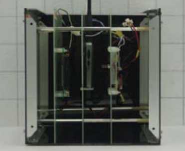
Figure 4. Typical satellite model
Where lr is the projectile residual length; l 0 is the projectile initial length; Yp is the yield strength of projectile; u 0 is initial penetration rate given by
v I ^ v c :
‘ v c < v I < ct : u 0
c t < v I :
u 0 = 0
v cos Q
-^— ( V c - 1.1 y sin Qu c ) (21)
1 + y 1 + y
u
I
1 + y
Where
Y =
is density ratio;
v =>
is critical
impact velocity required to initiate penetration;
uc

is critical penetration rate to initiate projec-
tile erosion, where Yp is the yield strength of projectile;
q = п I vl—vc_ I . As simulating and calculating, the resi-
21 C - v J dual length lr that projectile impacts the former thin plate will be the initial length that projectile impacts the later thin plate, when residual length is less than a certain value, the projectile is deemed to be used up and simulation ceases.
However, in the light of (20-1), after impacting only one thin plate with a thickness of 5mm and a velocity of 9km/s, the projectile with a diameter of 38cm and a length of 42cm will be thoroughly used up, this case obviously doesn’t match with the truth. By large computation and analysis, it finds that replacing the strength Yp with the projectile Young’s modulus Ep will be rational. Therefore (19-1) can be rewrite
lating and calculating, the residual velocity that projectile impacts the former thin plate will be the initial velocity that projectile impacts the later thin plate.
V. The Simulation Case Analysis
Based on the above model, programming and realizing with Matlab, 1999-025A satellite breakup event is chosen to validate the model, where projectile structure is also referred to the MHV [18] and parameter value is estimated according to Ref. [20]; the target parameter is referred to Ref. [21], because the mass component of target is unknown, assuming target wholly consists of aluminum alloy. Table 2 gives the parameters value both the target and projectile, except these for the projectile Ep = 7 x 10 10 Pa , for the target K c = 2.3 x 10⁷ Pa Q m1 / 2.
TABLE II.
T arget and projectile P arameters
|
Parameters |
m /kg |
p /(kg/m3) |
c /(m/s) |
Size /m |
Y /Pa |
|
Target |
950 |
2800 |
5200 |
1.5 x l.5 x l.5 |
4.2 x 10⁸ |
|
Projectile |
32 |
660 |
5200 |
Ф 0.38 x 0.42 |
4.2 x 10⁸ |
lr = 1 o exPh;^( VI - u 0) 2 ] 2 E p
(20-2)
The paper adopts the (20-2).
B. Projectile Velocity Degraded Model
The projectile velocity degraded model is established based on hydrodynamic-resistance kinematics [12]
In order to compare with NASA standard collision breakup model, assuming that projectile head-on normally impacts target, the impact velocity is 9km/s [22], considering the real structure of satellite, letting the thickness of thin plate be 5mm. Table 3 gives the number of fragments having a size larger or equal 5cm getting through the paper model, NASA model and US Space Surveillance Network (SSN), where SSN data is referred to Ref. [23].
vr = v I exp
'1
2 1 о J
When the projectile velocity is less than the ballistic limit velocity of the thin plate vl , the projectile will stop inside target. If the projectile hydrodynamic penetration depth is Ph = —, vl can be figured out by the following Y equation [19]
TABLE III.
N umber of fragments
Model Number of fragments
The paper model
NASA model
SSN data
Where
vl
. в 5 Г T /2 R
4k(1 + y) — —- ~--
aP p
a - b
0.5
b = 2 ky 2
( Y a = 1 + kI -r-l a

£Y T. aJl 2 R
-

As T t < P h , P = T t ;
T > P h , P = P h ;
k , a , в , X are constant related with material can let them be 1.0, 1.3, 0.465, 0.5 respectively. Ditto as simu-
Table 3 shows that the paper model data is more close to the surveillance data comparing with NASA model data. In the table, the data of the paper model and NASA model are get by assuming the projectile head-on normally impacts the target, based on the approximate extent of three series data, this impact pattern can be concluded to be reason that why so many fragments is produced in the 1999-025A satellite breakup event. The advantage of the paper model over NASA model is that comprehensively takes into account the factors influence on impact outcome such as projectile-target characteristic, impact velocity, impact position, impact angle, overcome the localization of the NASA model that only considers the impact velocity and mass of projectile and target. The result indicates that the paper model is effective and feasible, having important engineering reference value.
-
VI. Conclusions
-
(1) Establishing the average fragment size model depending on strain rate, according with Poisson statistic fragments are discrete and distribution model is set up;
-
(2) On the foundation of the constitution analysis for the space target and projectile, both the target and projectile equivalent model is established;
-
(3) The length and velocity degraded model is set up against the cylindrical projectile;
-
(4) Choosing typical case, Comparing the paper model, NASA model simulation data and SSN surveillance data, the paper model is validated.
The objective of the paper is to establish an effective and feasible engineering model for the impact breakup of the space target, the simulation case indicates that the goal is achieved and the paper model has important engineering reference value. Next step combing with the projectile-target interaction model the relation between impact parameters and impact effect will be studied, and the model can be further modified.
Acknowledgement
The paper is made possible through the support from the Institute of Electrical and Electronics Engineers, Incorporated (the “IEEE”) 2011 International Symposium on System Modeling, Simulation and Engineering Mathematics (SMSEM2011).
References Study on the Impact Breakup Model of the Space Target Based on the Thin Plate
- The NASA Orbital Debris Program Office, “Satellite Collision Leaves Significant Debris Clouds”, Orbital Debris Quarterly News, Vol. 13, pp. 1-2, April 2009.
- The NASA Orbital Debris Program Office, “Satellite Breakups During First Quarter of 2008”, Orbital Debris Quarterly News, Vol. 12, pp. 1-2, April 2008.
- T. D. Bess, “Mass Distribution of Orbiting Man-made Space Debris”, NASA TN D-8108, Langley Research Center, Hampton, VA, USA, December 1975.
- W. Fucke, H. Sdunnus, Population Model of Small Size Space Debris, Final Report of ESOC contract no. 9266/90/D/MD, Battelle-Institut, Frankfurt am Main, Germany, June 1993.
- N. L. Johnson, P. H. Krisko, J-C Liou, and P. D. Am-Meador, NASA’s new breakup model of EVOLVE 4.0 [J]. Advances in Space Research, Vol. 28, pp. 1377-1384 2001.
- M. Oswald, S. Stabroth, C. Wiedemann, P. Wegener, C. Martin, “Upgrade of the MASTER Model”, Institute of Aerospace Systems, M05/MAS-FR, 2006.
- X. Q. Ma, “Shock Dynamics”, Beijing: Beijing Institute of Technology Press, 1992.
- M. Hosseini, H. Abbas, “Growth of hole in thin plates under hypervelocity impact of spherical projectiles”, Thin-Walled Structure, Vol. 44, pp. 1006-1016, 2006.
- D. E. Grady, M. E. Kipp, “Impact failure and fragmentation properties of metals”, DE98004766, 1998.
- F. K. Schaefer, “An engineering fragmentation model for the impact of spherical projectiles on thin metallic plates”, International Journal of Impact Engineering,Vol. 33, pp. 745-762, 2006.
- F. Y. Lu, “One-Dimentional Nonsteady Hydrokinetics Tutorial”, Beijing: Science Press, 2006.
- X. Q. Ma,, F. Han, “High Velocity Impact Dynamics”, Beijing: National Defense Industry Press, 1998.
- L. T. Wilson, D. R. Reedal et al, “Comparison of calculated and experimental results of fragmenting cylinder experiments”, Sand2000-1406C, 2000.
- R. W. James, J. L. Wiley. “Space Mission Analysis and Design”, Beijing: Aviation Industry Press, 1992.
- F. X. Xu, “Satellite Engineering”, Beijing: China Aerospace Press, 2002.
- The NASA Orbital Debris Program Office, “Three New Satellite Impact Tests”, Orbital Debris Quarterly News, Vol. 11, pp. 4-5, October 2007.
- C. Carrasco, J. Osegueda et al. “Modeling Hypervelocity Impact for Kill Enhancement of Ballistic Missile Warheads” ADA366234, 2004.
- S. K. Remillard. “Debris Production in Hypervelocity Impact ASAT Engagements”, ADA230467, 1991.
- F. I. Grace. “Ballistic limit velocity for long rods from ordnance velocity through hypervelocity impact”. International Journal of Impact Engineering, Vol. 23, pp. 295-306, 1999.
- The NASA Orbital Debris Program Office, “Physical Properties of the Large Fengyun-1C Breakup Fragments”, Orbital Debris Quarterly News, Vol. 12, pp. 4-5, April 2008.
- N. L. Johnson. “History of on-orbit satellite fragmentations 14th edition”. Houston: NASA, 2008.
- The NASA Orbital Debris Program Office. “Fengyun-1C Debris: One Years Later”,. Orbital Debris Quarterly News, Vol. 12, pp. 2-3, January 2008.
- The NASA Orbital Debris Program Office. “Fengyun-1C Debris: Two Years Later”,. Orbital Debris Quarterly News, Vol. 13, pp. 2, January 2009.
