
Sub-terahertz compact high-efficiency elliptic cross-shaped radiating patch antenna design for short-range wireless communication systems

Журнал: Физика волновых процессов и радиотехнические системы @journal-pwp
Статья в выпуске: 3 т.29, 2026 года.
Бесплатный доступ
Background. Sub-terahertz communication systems demand compact, wideband, and highly efficient antennas to support high-data-rate transmission and sensing applications. Achieving such performance within a limited footprint remains a significant design challenge. Aim. This work aims to design a compact sub-THz antenna with wide impedance bandwidth, high radiation efficiency, and stable radiation characteristics suitable for short-range communication and sensing applications. Methods. An elliptical cross-shaped radiating patch is designed on a Rogers RO4835-T substrate and excited using a microstrip-line feed. A partial ground plane is employed to enhance impedance bandwidth. Additionally, two tapered strips are incorporated near the upper edges of the patch to further improve antenna performance. Results. The designed antenna reaches an impedance bandwidth of approximately 0.179 THz, covering the frequency range from 0.092 THz to 0.271 THz with S11 < –10 dB, corresponding to a wide bandwidth of about 98.55 %. The antenna demonstrates high radiation efficiency of nearly 95 % across the operating band. It exhibits an omnidirectional radiation pattern and maintains a compact size of 1000 × 1000 × 64 μm³ λλλλ being the wavelength at the lowest frequency). Conclusion. The proposed antenna offers an effective solution for sub-THz applications due to its compact size, wide bandwidth, and high efficiency, making it suitable for short-range communication and sensing systems.
Короткий адрес: https://sciup.org/140316773
IDS: 140316773 | УДК: 621.396.67:621.39 | DOI: 10.18469/1810-3189.2026.29.3.7-14
Разработка компактной высокоэффективной субтерагерцовой антенны с эллиптическим крестообразным излучающим патчем для систем беспроводной связи малого радиуса действия
Обоснование. Системы связи субтерагерцового диапазона требуют компактных, широкополосных и высокоэффективных антенн для поддержки передачи данных с высокой скоростью и приложений зондирования. Достижение таких характеристик в ограниченных габаритах остается значимой задачей проектирования. Цель. Целью исследования является разработка компактной суб-ТГц антенны с широкой полосой согласования по импедансу, высоким КПД излучения и стабильными характеристиками излучения, пригодной для связи малого радиуса действия и задач зондирования. Методы. Излучающий патч эллиптической крестообразной формы выполнен на подложке Rogers RO4835-T и возбуждается микрополосковой линией. Для расширения полосы согласования по импедансу используется частичная земляная плоскость. Кроме того, вблизи верхних кромок патча введены два сужающихся элемента для дальнейшего улучшения характеристик антенны. Результаты. Разработанная антенна обеспечивает полосу согласования по импедансу около 0,179 ТГц, охватывая диапазон частот от 0,092 до 0,271 ТГц при S11 < –10 дБ, что соответствует широкой относительной полосе около 98,55 %. Антенна демонстрирует высокий КПД излучения, достигающий почти 95 % в рабочей полосе. Она обладает всенаправленной диаграммой направленности и компактными габаритами 1000 × 1000 × 64 мкм³ λλλ где λ – длина волны на нижней рабочей частоте). Заключение. Предложенная антенна является эффективным решением для суб-ТГц приложений благодаря компактным размерам, широкой полосе и высокому КПД, что делает ее пригодной для систем связи малого радиуса действия и зондирования.
Текст научной статьи Sub-terahertz compact high-efficiency elliptic cross-shaped radiating patch antenna design for short-range wireless communication systems
Recently, wireless communications have been developing rapidly. Consequently, the need for faster data speed and larger bandwidth is becoming prominent. Many researchers today are investigating ultra-wideband (UWB) and super-wideband (SWB) antenna designs to meet these requirements. These designs play a double role by enhancing communication performance and bridging the gap between wireless and wired systems [1]. The THz band, which refers to the frequency range between approximately 0.1 THz and 10 THz, is currently being utilized for next-generation communication systems. More specifically, there has been extensive research interest in the sub-THz region (0.1–0.3 THz) [2]. The availability of very large bandwidth makes the frequency range capable of supporting very high data rates. In addition, it provides improved quality levels. The interference level is also very small. Moreover, the blockage impact is not substantial, unlike in mmW communication systems. A significant issue with this frequency range is its very high propagation losses and atmospheric absorption. As a result, this shortens the communication range to about 10–15 m for most cases. Thus, THz communication systems may be applicable mainly for indoor or short-distance applications.
Beyond communication systems, THz technology has found applications in several other fields. For instance, in medical imaging, its non-ionizing properties allow safe interaction with biological tissues, enabling detailed analysis [3]. In addition, upcoming sixth-generation (6G) communication systems are expected to make use of THz frequencies to support ultra-high-speed data transmission [8]. Other potential applications include radar sensing, environmental monitoring, and space exploration [4]. Despite these promising applications, research on THz antennas is still relatively limited compared to microwave and millimeter-wave technologies. This is mainly due to practical challenges in measurement techniques and the high computational requirements involved in simulation processes [5–7].
In this study, a sub-terahertz microstrip antenna with a simple unslotted design is introduced. The proposed design achieves an average radiation efficiency of about 95 % and operates over a frequency range of 0.092 to 0.271 THz, which corresponds to a fractional bandwidth of 98.55 %. The antenna is also compact, measuring 0.307 Xx 0.307 Xx 0.019 X , where X represents the wavelength at the lowest operating frequency.
The remainder of this paper is organized as follows: Section 1 discusses the antenna design methodology, Section 2 explains the design procedure,
a
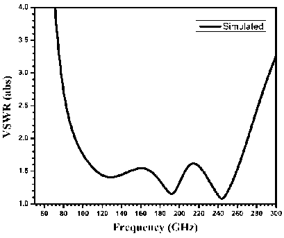
Fig. 2. VSWR plot for the proposed antenna
Рис. 2. График КСВН предложенной антенны
b
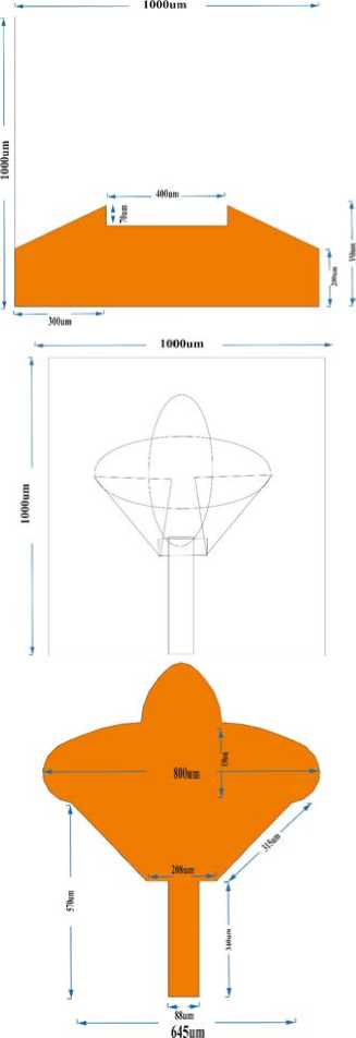
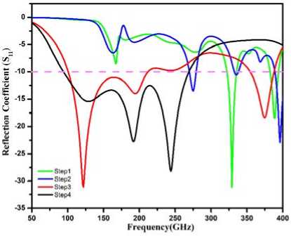
Fig. 1. ( a ) dimensions of the proposed antenna; ( b ) reflection coefficient variation from Step 1 to Step 4
Рис. 1. ( а ) габаритные размеры предложенной антенны;
( б ) изменение коэффициента отражения от шага 1 к шагу 4
Section 3 presents and analyzes the obtained results, and Section 4 provides the conclusion.
1. Design of Antenna
The proposed antenna was built on a Rogers RO4835-T substrate, which has a relative permittivity of 3.52 and a loss tangent of 0.003. The overall size of the antenna is 1 × 1 × 0.064 mm³. The design and parameter optimization were carried out using ANSYS HFSS simulation software.
The radiating structure lies on the top surface of the substrate and features an elliptic cross-shaped patch without any slotting. A microstrip feed line excites this patch, as shown in Fig. 1 ( a ). On the bottom side, a partial ground plane is implemented. Additionally, two tapered strips are introduced near the upper edges of the ground plane to enhance both bandwidth and gain performance.
A 50 Ω microstrip line feeds the antenna. After the optimization process, the finalized design parameters are summarized in Fig. 1 ( a ), while Fig. 2 shows the corresponding VSWR response.
2. Step-by-Step Design Procedure
The antenna is designed for a lower resonant frequency of 92 GHz. The total dimensions of the fabricated structure remain consistent at 1 × 1 × × 0.064 mm³. The design evolution process is shown in Fig. 3.
• Step 1. First, an elliptic cross-shaped radiating patch is used with a full ground plane on the other side of the substrate. This setup creates a resonance near 325 GHz. However, the impedance bandwidth is very narrow, making it unsuitable for sub-terahertz applications.

a b c d
Fig. 3. Step-by-step design procedure of the proposed antenna
Рис. 3. Пошаговая процедура проектирования предложенной антенны
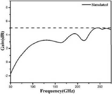
Fig. 4. Gain plot for the proposed antenna
Рис. 4. График усиления предложенной антенны
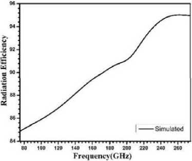
Fig. 5. Radiation efficiency plot for the proposed antenna
Рис. 5. График КПД излучения предложенной антенны
• Step 2. To improve the bandwidth, two triangular strips are added at the lower part of the vertical elliptical patch [8]. This adjustment shifts the resonant frequency to around 275.39 GHz. There is a slight improvement in impedance characteristics, but the performance still falls short of the required standard.
• Step 3. Further improvement comes from replacing the full ground plane with a partial ground plane [9], which produces two resonant frequencies of about 122.43 GHz and 195 GHz. This change results in a notable increase in bandwidth at both the lower and higher frequency ranges. Despite this advance in performance, it is still not sufficient for effective use at sub-terahertz levels.
• Step 4. In the final stage, the partial ground plane is modified by adding two tapered strips near its upper edges. This adjustment greatly enhances the impedance bandwidth compared to earlier setups, making the antenna suitable for sub-terahertz applications. At this point, three resonant frequencies are observed at 128 GHz, 192 GHz, and 244 GHz.
3. Results and Discussion
The optimized antenna structure has an impedance bandwidth ranging from 92 GHz to 270.74 GHz and a center frequency of 181.37 GHz. Additionally, the bandwidth corresponds to a fractional bandwidth of 98.55 %.
-
Fig. 2 shows the VSWR plot over the impedance bandwidth region, where the VSWR value is maintained below 2 throughout the region. This reconfirms the wide fractional bandwidth of 98.55 %.
The overall gain of the antenna at various frequencies is shown in Fig. 4. The peak simulated gain of 5.04 dBi is achieved at a frequency of 244 GHz. The antenna provides stable and good gain throughout the entire impedance bandwidth.
-
Fig. 5 presents the radiation efficiency versus frequency characteristics. The maximum simulated efficiency reaches 95 %, and across the impedance bandwidth, the radiation efficiency consistently remains between 86 % and 95 %, demonstrating the effectiveness of the proposed design.
As the operating frequency rises, the peak gain of the antenna also increases. This is due to the patch’s effective electrical size becoming larger compared to the wavelength, which makes the antenna more efficient in radiating power and providing higher gain.
-
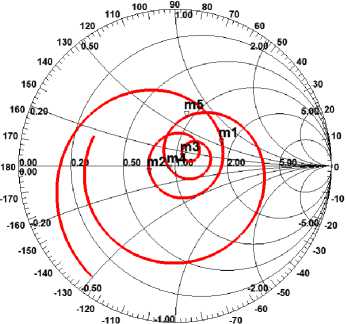
Fig. 6 ( a ) illustrates the Smith chart plot of the proposed antenna. It is evident from the plot that the reflection coefficient is very small, and the normalized impedance at the resonance frequencies is nearly equal to unity. This indicates excellent impedance
Smith Chart 1
|
Name |
Freq |
Ang |
Mag |
RX |
VSWR |
|
|
ml |
92.0000 |
25.2213 |
0.3336 |
1.7504 + 0.55991 |
0.3198 |
2.0010 |
|
m2 |
128.0000 |
■164.2344 |
0.1691 |
0.7173-0.0679! |
0.0946 |
1.4071 |
|
m3 |
192.0000 |
41.4140 |
0.0727 |
1.1099 + 0.10731 |
0.0967 |
1.1568 |
|
m4 |
244.0000 |
-142.2195 |
0.0389 |
0.9393-0.04481 |
0.0477 |
1.0809 |
|
m5 |
270.7400 |
76.2740 |
0.3256 |
0.9395 + 0.6649i |
0.7077 |
1.9657 |
-100 .go -80
b
a
c
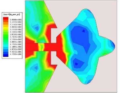
Fig. 6. Proposed antenna: Smith chart plot ( a ); simulated surface current distribution at 128 GHz ( b ); simulated surface current distribution at 192 GHz ( c ); simulated surface current distribution at 244 GHz ( d )
Рис. 6. Предложенная антенна: диаграмма Смита ( а ); распределение поверхностного тока на частоте 128 ГГц ( б ); распределение поверхностного тока на частоте 192 ГГц ( в ); распределение поверхностного тока на частоте 244 ГГц ( г )
d
matching at those resonance frequencies, thereby validating the effectiveness of the antenna design.
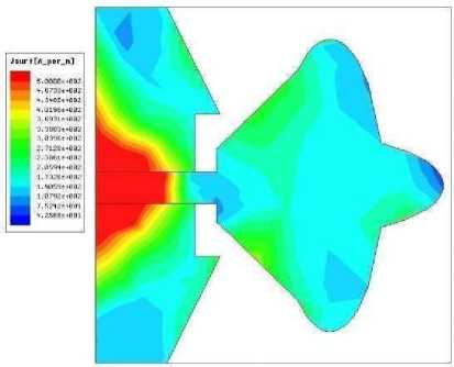
Fig. 6 ( b ) shows the current flow pattern on the surface [6] of the sub-terahertz antenna at its 128 GHz resonant frequency. The pattern reveals that the microstrip feedline and partial ground plane exhibit maximum current concentration. This portion is responsible for creating a resonance at 128 GHz.
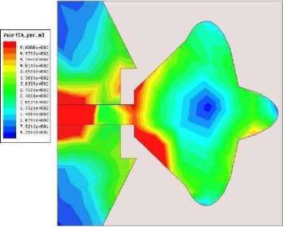
Fig. 6 ( c ) shows the surface current pattern of the antenna at its 192 GHz resonant frequency. The pattern reveals that the two tapered strips of the vertical elliptical patch exhibit higher current concentration. This portion is responsible for creating a resonance at 192 GHz.
Fig. 6 (d) shows the surface current pattern of the antenna at its 244 GHz resonant frequency. The pattern reveals that the partial ground plane with two tapered strips at both top corners of the ground plane exhibits higher current concentration. This portion is responsible for creating a resonance at 244 GHz.
These behaviors confirm the excitation of fundamental resonating modes and contribute to improved impedance matching across the entire operating bandwidth.The presence of tapered strips in the partial ground plane [10] enables bandwidth enhancement. From an electromagnetic point of view, the tapered structure provides multiple current paths of different electrical lengths and, consequently, can excite additional resonant modes. The gradual reduction in the width of the ground plane helps to prevent sudden impedance transitions between the feedline and the radiating patch and thus improves impedance matching. It also provides stronger capacitive coupling at the highest-frequency side, which results in the excitation of resonant modes at about 192 and 244 GHz. These two effects together
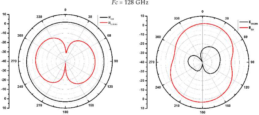
Fig. 7. Radiation pattern for the XZ plane ( a ); Radiation pattern for the YZ plane ( b )
Рис. 7. Диаграмма направленности в плоскости XZ ( а ); Диаграмма направленности в плоскости YZ ( б )
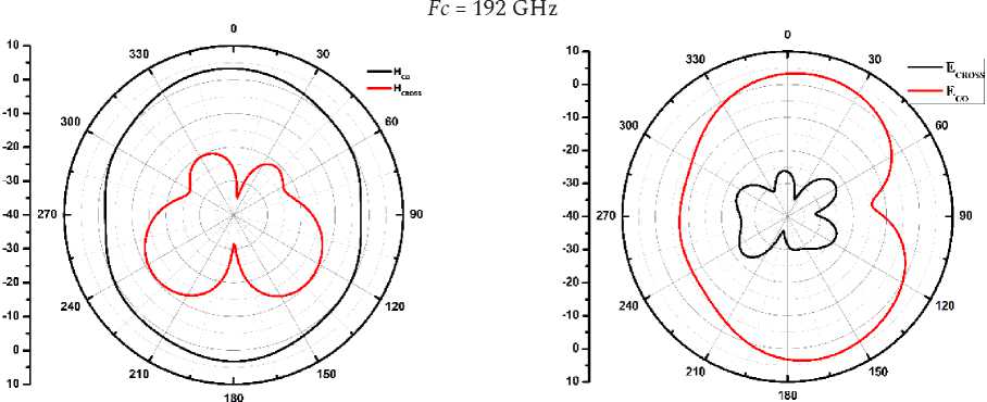
Fig. 8. Radiation pattern for the XZ plane ( a ); Radiation pattern for the YZ plane ( b )
Рис. 8. Диаграмма направленности в плоскости XZ ( а ); Диаграмма направленности в плоскости YZ ( б )
Fc = 244 GHz
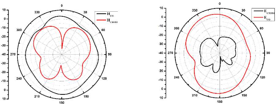
Fig. 9. Radiation pattern for the XZ plane ( a ); Radiation pattern for the YZ plane ( b )
Рис. 9. Диаграмма направленности в плоскости XZ ( а ); Диаграмма направленности в плоскости YZ ( б )
explain the large enhancement in impedance bandwidth after adding the tapered extensions.
Figs. 7 ( a ), 8 ( a ), and 9 ( a ) show the magnetic field (H-plane) radiation patterns for co-polarization and cross-polarization.
It is observed that the co-polarized component ( H ) is significantly stronger than the cross-polarized component ( H ), indicating good polarization purity.
Table. Comparison of the Proposed Antenna with Related THz Antennas
Таблица. Сравнение предложенной антенны со сходными ТГц-антеннами
|
Reference No., year of publication |
Dimensions (mm3) |
Bandwidth (GHz) |
Maximum radiation efficiency (%) |
Peak gain (dBi) |
|
No. 5, 2019 |
322 × 280 × 58 |
293–410 |
89 |
5.14 |
|
No. 6, 2020 |
500 × 500 × 0.5 |
47 GHz at a resonance frequency of 0.607 GHz |
89.79 |
9.75 |
|
No. 7, 2024 |
2.51 × 4.12 × 0.127 |
100–110 |
85 |
7.65 |
|
Proposed work |
1 × 1 × 0.064 |
92–271 |
95 |
5.04 |
Similarly, Fig. 7 ( b ), Fig. 8 ( b ), and Fig. 9 ( b ) present the electric field (E-plane) radiation patterns for copolarization and cross-polarization. The co-polarized component ( E ) is noticeably higher than the cross-polarized component ( E ), ensuring stable radiation characteristics.
These results validate that the proposed antenna maintains desirable radiation behavior across the sub-terahertz operating band.
The Table provides a comparison between the proposed antenna and other recently reported designs [5–7]. This comparison shows that the proposed antenna offers improved performance in terms of impedance bandwidth, gain, radiation efficiency, and compactness, highlighting its advantages over existing works.
Conclusion
In this work, an unslotted and structurally simple elliptic cross-shaped radiating patch antenna is proposed and analyzed for sub-THz applications.
With suitable modifications, the impedance bandwidth performance is improved. The designed antenna operates in the frequency range from 0.092 THz to 0.271 THz. This corresponds to an enhanced, wide fractional bandwidth of 98.55 %. The designed antenna achieves a high radiation efficiency in the range of 0.86 to 0.95 over the operating band. The compact size of the proposed antenna is 0.307 Xx 0.307 X . It is found that the designed antenna has the capability to generate stable and efficient performance in the desired band.
Therefore, the proposed antenna achieves the design goal by effectively covering the sub-THz band (0.1–0.3 THz). It also achieves an average radiation efficiency higher than 0.9 in the operating band. Antenna designs with high complexity have been introduced for THz applications; the simplicity of the slotless design and its geometry, by contrast, make the proposed antenna more practical and easier to implement in derived prototypes. Thus, the proposed antenna may be considered a good candidate for future sub-THz communication and sensing.