Supervision Architecture Design for Programmer Logical Controller Including Crash Mode

Author: Bennani fatima zohra, Sekhri Larbi, Haffaf Hafid
Journal: International Journal of Information Technology and Computer Science(IJITCS) @ijitcs
Article in issue: 11 Vol. 6, 2014.
Free access
This paper is a contribution for development of a high level of security for the Programmer Logic Controller (PLC). Many industrial adopt the redundant PLC architecture (or Standby PLC) designed to replace the failed (out of order) PLC without stopping associated automated equipments. We propose a formal method to choose a Standby PLC based on probability study, by comparing normal functioning to misbehavior one leading to residue generation process. Any generated difference reveals a presence of anomaly. The proposed method begins by listing all PLC components failures leading to their stopping according to failures criticalities. Two models; functional and dysfunctional are obtained by using formal specifications. Probability’s calculus of dysfunction of each Standby PLC is obtained by the sum of the probabilities of dysfunction of its critical components. These probabilities are allocated each transition which leads to the dysfunction in the dysfunctional model. The dysfunctional model is obtained by using the FMECA method (Failure Modes, Effects and Criticality Analysis). We shall see that this global vision of functioning of the whole PLC leads to a higher level of security where the chosen Standby PLC works continuously.
Programmer Logic Controller, Supervision, Petri Nets, UML, STEP7, PLCSim, Protool
Short address: https://sciup.org/15012186
IDR: 15012186
Text of the scientific article Supervision Architecture Design for Programmer Logical Controller Including Crash Mode
Published Online October 2014 in MECS
The complexity of Automated Production Systems (APS) and demand from industrial partners for equipments availability, make functioning surety of Programmer Logic Controller (PLC) a major preoccupation of managers in industrial domain [1] and [2]. In fact, emergency stopping of industrial processes caused by their failed automaton leads to undesirable situations. Nowadays, the Standby PLC constitutes the most adopted solution by industrial companies aiming to improve their performance. The study of operating PLC safety has occupied an important place in the industry. It represents capacity of an entity to realize one or several required functions in a given conditions [3] and [4]. This study is based on important parameters like reliability, availability and maintainability.
The need to develop formal methods enabling to know nominal and degraded behavior of Standby PLCs in order to evaluate their abilities to provide services and to replace the PLC failure without causing damages to environments, persons, etc. is very important. Many formal methods using different approaches for specification and validation systems controlled by PLC exist in literature. These works represent a current field which concerns researchers of the automatic control community and the computer science community [5], [6], [7], [8] and [9]. Other works on specification languages, models and tools have been developed for modeling and analyzing systems controlled by PLC dealing with concepts as stability, controllability and diagnosability [10], [11], [12] and [13]. Among existing models in literature we can give bond graph model [14] and [15], Petri nets [16] and [17], automaton and timed automaton [18], [19], [20] and [21] for the supervisory control.
Several solutions were proposed in this context such as the redundancy. Indeed, the redundancy concept is defined in the safety standard [22] as the existence of different ways to fulfill a required function. Among the physical redundancy, we have the redundancy of some critical components of the PLC like central unit (CU), power block, etc. [23] and [24]. Recent trends toward PLC redundancy solution are called Standby PLC [25] where the functioning is based on the information supplied on the functioning state of the PLC, allowing replacing it once it breaks down. In this paper, we are interested by the Standby PLC which has proved its efficiency in the domain of operating safety. Unfortunately, industrial companies adopting this solution are in face to another problem, which is the not starting up of the Standby PLC. This problem will be discussed and dealt in this paper.
The paper is organized as follows: Section 2 introduces the Standby PLC problematic and the associated architecture. In section 3, our supervision architecture and proposed approach are given. In section 4, activity diagrams and correspondent Petri nets of PLC functioning and dys-functioning are illustrated. Section 5 deals with a case study consisting in six automated compressors controlled by three PLC where each one is responsible on both two compressors. In this section our supervisor PLC system is proposed, the method is applied and a detailed analysis using STEP7 Package software to platform design, PLCSIM and PROTOOL for simulation. Finally, we conclude our work and discuss some perspectives.
-
II. Standby PLC Problem
The Standby PLC solution brought many solution elements to the PLC failure problem. The most dangerous is the no starting up of the Standby PLC after a principal PLC failure which causes the stopping all the managed automated equipments. This accident is explained by the loss of information of the principal PLC functioning’ state, and is due to the breaking connection between the Standby PLC and the principal PLC, transmission delays or keeping standby PLC busy by other tasks. Our work concerns a supervisor PLC design loaded to control the entire PLC which also encompass Standby PLC by choosing the best (Standby PLC).
The architecture of Standby PLC belongs generally to two categories [26]:
-Active redundancy: The Standby PLC operates simultaneously with the principal PLC while ensuring the same tasks.
-Passive Redundancy: One PLC ensures the control. The shift towards the Standby will be made after a principal PLC failure.
In this work, we consider the first category. This category is adopted by several companies, where each PLC working on production site is also configured to work as Standby PLC. The Standby PLC architecture is illustrated by the Fig. 1.
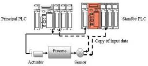
Fig. 1. Standby PLC architecture
The main functions of the Standby PLC are to acquire and record the input RAC (Real Application Clusters:
copy of the input) of the principal PLC and to get back cyclically the information on the state of the principal PLC functioning [27].
-
III. Adopted Approach
Several methods were proposed to ensure the supervision task. A method is selected on the dealt information nature, the system complexity and the dynamics of the system. Indeed, it is important to distinguish between different existing supervision methods developed for the continuous, discrete and hybrid systems. In this work we consider hybrid systems needing both models: continuous and discrete. The controlled system is a PLC representing a hybrid system treating continuous values and discrete events studied in both normal and degraded functioning mode. The approach deals with the functional /dysfunctional analysis of the PLC. The supervision method aims to detect a generated residue by comparing the real functioning of the system to its functional model (model of normal functioning, see Fig. 2.
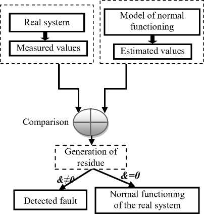
Fig. 2. Residue generation
Designing supervision architecture for PLC involves a supervisor design and a reconfiguration of Standby PLC architecture. This can be done by data acquisition, failure detection, and diagnosis and system control. The data acquisition consists to collect all information about a controlled system. The failure detection and the collected information serve to make decision on the controlled system: it is in normal mode or not. The diagnosis consists in Fault Detection and Isolation (FDI) so that corrective actions can be taken to eliminate the effect on the overall system performance.
The main functions ensured by the proposed approach are:
-
1- Supervision of all PLCs.
-
2- Prevision of PLCs failures.
-
3- Select the Standby PLC based on probability calculus.
The functional model of the designed PLC describes its functioning by exposing different existing relations between captured data and the orders sent by the PLC. To ensure the control of failure of functioning of the PLC, a functional state control program of each critical component is integrated in the supervisor. These components are represented by variables controlled by predefined thresholds. The Standby PLC selection uses a probability study as described by the following phases:
Phase1 : Listing all the failures that can arise at the PLC. This list is given by a dysfunctional analysis of the PLC based on FMECA method ( Failure Modes, Effects and Criticality Analysis). Fig. 3 depicts the functioning of FMECA method.
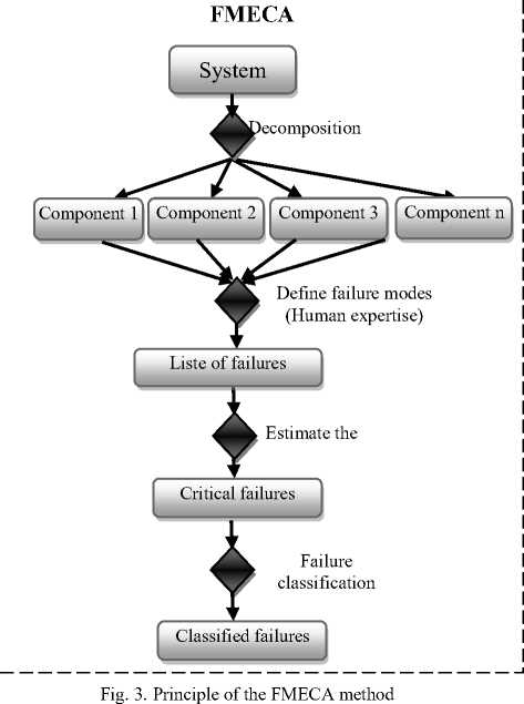
This method begins by system decomposition into simple components, a defined list of the possible failures which can arise in the PLC (information given by the domain experts) and selected failures causing the stopping of the PLC.
Phase2. In this phase, we compute the failures number observed in a time interval - t called X (t) rate of the failed PLC. Indeed, we adopt the exponential law to compute this parameter.
λ (t)=1/MTBF (1)
MTBF (Mean Time between Failures) is the mean time before appearance the PLC failure.
Phase 3: For each PLC component, the appearance probability of a failure p (t) in a time interval is computed.
p(t)=1-e λ (t) (2)
Phase 4 : We affect p (t) parameter to each faulty component. The probability of PLC dys-functioning is given by:
P(t)= p(t) i=1…n (3)
i is the faulty component number.
The formula (3) enables us to compute the probability of PLC normal functioning.
F (t) =1- P(t) (4)
The formula (4) serves to the supervisor to choice the Standby PLC by selecting a PLC having a high value of F(t) and the less occupied (from the variable defining its CPU). Once the Standby PLC is chosen, the supervisor orders him to replace the failed PLC.
-
IV. PLC Functioning Model
Our aim is to propose a solution based on a formal analysis model which could be translated into supervisor program. The integrated model must be able to control all PLCs while ensuring the continuity of functioning of controllable equipment. The PLCs are complex systems and their formal modeling is a difficult task. Thus, the adopted methodology suggest passing through a semi-formal model like State-chart or UML (Unified Modeling Language). UML Diagrams are the most used in the industry and are well adapted to complex systems specification, unfortunately, their formal analysis requires translation tools to a formal model [28]. Such specification tools are more oriented to the Grafcet or Petri nets. In the sequel, we present two UML based models: PLC functioning model and PLC dys-functioning model.
The activity diagrams are chosen to model the PLC behavior. In the modeling process, an action represents a single step inside an activity and its execution represents a transformation or a treatment. “Fig. 4, 5 and 6”
illustrate respectively activity diagrams for PLC functioning model, PLC dys-functioning model and PLC model selection.
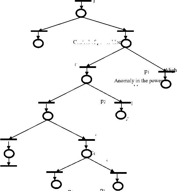
The dys-functioning of a PLC is caused by errors that arise during its functioning mode. We distinguish two categories of errors: Fatal errors generally leading to stopping the PLC and no fatal errors that don’t stopping its functioning. When a failure is detected, a corresponding error message is displayed on the programming console or another device connected to the PLC. In this work, we are interested by fatal errors. We distinguish four fatal errors which interrupt immediately the PLC:
-
1- Power bloc failure;
-
2- Central processing unit (CPU) failure;
-
3- Data transfer error between the CPU and input/output cards;
-
4- Input/output card failure.
These errors are obtained using the FMECA method allowing c a selection of critical failures leading to stopping PLC.
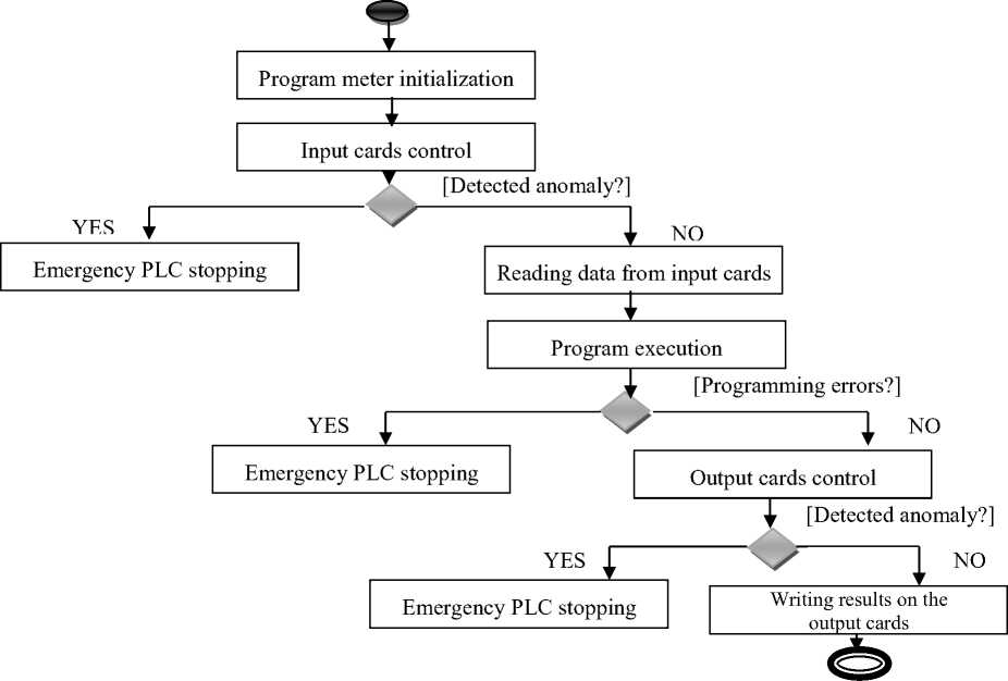
Fig. 4. Activity diagram of PLC functioning model
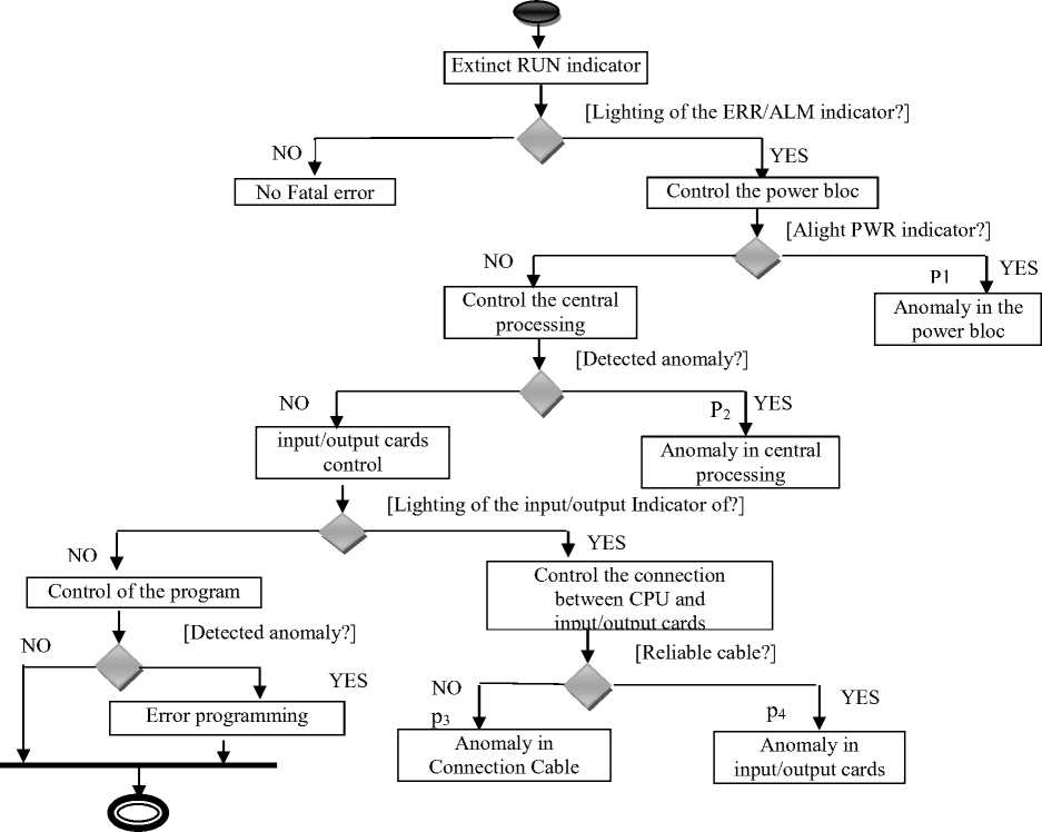
Fig. 5. Activity diagram of PLC dys-functioning model
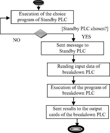
Fig. 6. Activity diagram selection of the standby PLC model
In this model, the probability of PLC dys-functioning in a time interval £1 t is defined as:
P(t)=p 1 (t)+p 2 (t)+p 3 (t)+p 4 (t) (5)
Activity diagram selection of PLC replacement
Once the supervisor detects a PLC failure, the choice program execution of the Standby PLC is launched by this supervisor. Once the PLC is chosen, the supervisor orders it to replace the failed PLC by modifying its input variable to 1 that initially set to 0. The Standby PLC verifies cyclically this variable, if it is equal to 1, it reads the input variables of the PLC that is out of order, executes its program and sends the orders to the concerned auctioneers. Each PLC’s program takes into account all automated equipments: sensors (input variables), auctioneers (output variables).
Integrating these models into supervisor’s program passes by their formal specification. Two approaches exist in literature [28]. For the first approach, it is recommended to remains in UML, the second approach aims to translate UML model into a formal specification. The translation process exploits a set of rules describing how a model expressed in a source language can be transformed into a target language. The graphical description model offered by UML is saved while exploiting techniques and tools of formal verification. For simplicity reasons we adopt the second approach where the Petri net model is selected as a formal language. Petri nets are chosen for many reasons since the activity diagram has a semantic close to the Petri nets. Another reason is Petri nets allow us to analyze various system behavioral aspects.
The translation of the activity’s diagrams into Petri nets holds an important place in the proposed approach. ‘Fig. 7” gives the main translation rules.
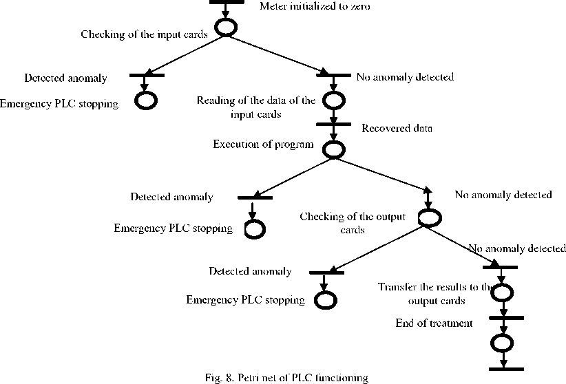
We present in the sequel, three Petri nets (Fig. 8, 9 and 10) corresponding respectively to the three previous activity diagrams depicted in Fig. 4, 5 and 6.
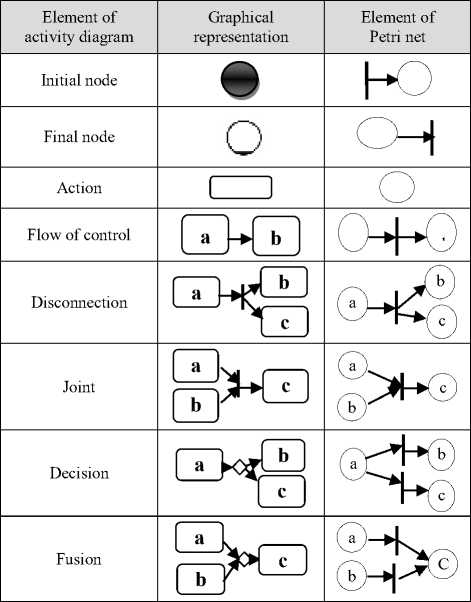
Fig. 7. Translation rules
-
V. Industrial Case Study
-
A. Introduction
Simulation experiments have been carried out on automated production system (APS) within SONATRACH Company. This company ensures the treatment of the crude product of LPG (Liquefied Petroleum Gas) . LPG products are forwarded by the deposits from the south of Algeria (Sahara) through pipelines for the production of the commercial propane and butane. These products once treated, are saved in storage back.
The test bed on which the simulation has been carried out consists in the compressor equipment. The company possesses six compressors which are managed by three PLC. Each PLC is responsible, at the same time, of functioning of two compressors. These PLC are programmed to ensure the replacement function if one of them is stopped. A danger can arrive when crash event occurs in the system leading to huge economic cost for the company.
This solution offers several advantages like global vision of PLC functioning and increases availability and reliability of PLC. The proposed system provides a data base which could be used by the specialists of the company (rate of failure of each PLC, probability of wellfunctioning, etc.).
-
B. System Design
Our approach needs four steps:
-
- Supervisor PLC design.
-
- PLC program modifications.
-
- Defining the control information to be sent to the supervisor.
-
- Connection supervisor- PLC and reconfiguration of the PLC architecture.
Extinct RUN indicator
Indicator
no fatal error
No detected anomaly
Control of the input/output cards
Extinct ERR/ALM
Extinct PWR indicator
Control the CPU
Extinct input/output indicator
Control of power blo
t PWR indicator
Alight input/output indicator
bloc
Detected anomaly
Anomaly in the CPU
No anomaly detected
Detected anomaly
Connection Problem
Anomaly detected in input/output cards
Fig. 9. Petri net of PLC dys-functioning
ontrol the connection between the CPU and the input/output cards
Execution of the program the breakdown PLC
Received order
Recovered data
End of execution
End of treatment
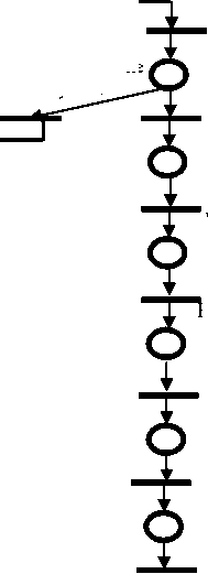
Standby PLC chosen
Breakdown of the PLC
Read the data of the breakdown PLC
Sent message to Standby PLC
Sent the results to output cards
Fig. 10. Petri net of the standby PLC selection
Standby PLC not chosen
Execution of the program of the supervisor to choice the Standby PLC
Remark. The designed system represents a virtual station. This means that the three PLC and a supervisor form a virtual PLCs running on simulation platform, i.e. a virtual station CPS (Console of Programming and Simulation) in order to show the simultaneous functioning of the APS parts.
The CPS station solution was already proposed in our previous work to ensure the PLC functioning without program errors. This solution was used to simulate the functioning of the supervision system. The PLC project (program and its configuration) is transferred from the real PLC to the virtual station by connecting it to the PLC. The final configuration consists in a supervisor project and three PLC projects, all transferred from the real PLC.
-
C. Modelling and Simulation
In our approach we have used STEP7 Package software (from Siemens) to platform design and, PLCSIM and PROTOOL for simulation [27]. STEP7 is very adapted for supervisor PLC programming; it is a part of SIMATIC software [27]. STEP7 is formed by two parts: Software part represents the user executive PLC program and the hardware part describes the physical configuration of the process.
SIMATIC is a hierarchy of objects similar to directories tree structure and files in Widows system. Fig. 12 below illustrates this hierarchy.
^^ Projet
Г В fall Statton
Q til Module programmable
В IStI Programme S7
I p | Sources
Blocs
Fig. 12. Tree structure
A project enables grouping data set and programs necessary to automated solution. A station is a hardware configuration containing many programmable modules. Three programming languages are part of the base software.
-
• Contact scheme ‘CONT’ is a graphical programming language. The syntax is very closer to circuit scheme. The scheme elements like closing and opening contact are put in a network.
-
• Instructions list ‘LIST’ is dedicated to coding critical applications; it is a textual programming language close to the machine
-
• Logogram ‘LOG’ is a graphical programming language using graphical functional boxes of Boolean algebra to represent logical operations.
Two simulators are used:
-
- S7-PLCSIM simulator enables the execution and testing user program in PLC. It gives a simple interface with user program to display different objects like input/output and program tracing.
-
- PROTOOL Simulator enables online simulation. The control panel represents a communication medium between automaton and operator. It is relies on interfaces visualizing state process. The system architecture is illustrated by the Fig. 13.
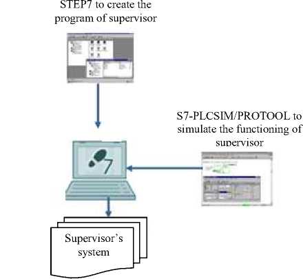
Fig. 13. General architecture of the supervision system
-
D. Simulation and Results
-
• Simulated system description
The functioning of the simulated system is a PLC, which is a computer dedicated to control the industrial process by a sequential treatment. It receives the information on the state of process functioning from the sensors and sends orders to the actuators. The main functions of the PLC are acquisition of input data and their processing, and emission of the orders.
-
• Creation of the new project of the supervisor PLC
The project is a root grouping hierarchical objects: Station, CPU, program, etc. At this level we create project and station. By Hardware tool we configured the PLC hardware part: CPU, alimentation block, communication network, input /output cards and control/command panel [28].
Each PLC has three panels. A new display is created for Supervisor PLC (SPLC) to control other PLCs. Fig. 14 illustrates a hardware configuration of our system.
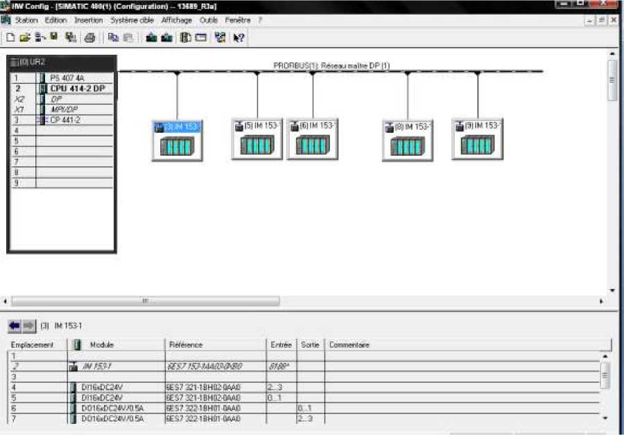
Fig. 14. Hardware configuration
-
- CPU and alimentation block are the same that used by PLCs
-
- MODBUS network is used to connect the
supervisor to PLCs.
-
- Input variables created in the supervisor to communicate with the PLC1 are :
-
1- State’s variable of alimentation block of PLC1.
-
2- State’s variable of PLC1 processor.
-
3- State’s variable of functioning I/O cards of PLC1.
-
4- Link state’s variable between CPU and I/O cards
In the same manner other variables are created enabling the supervisor (SPLC) to communicate with PLC2 and PLC3.
-
- Three output variables for PLC initialized to 0 and set to 1 when SPLC gives a replacement command.
SPLC program is based on functioning/dys-functioning model to control PLC functioning by his input variables. When a fatal error occurs in a PLC, SPLC asks another PLC to replace it by using his output variable set to 1. Contact schema CONT is used to program development.
These variables are used by the supervisor to predict the PLC failure. They are also used to compute the probability of PLC dysfunction to choose the standby PLC.
-
• Development of the supervisor's program
The program of the supervisor contains three data blocks (DB1, DB2 and DB3) with I/O variables of each
PLC. Three functional blocks (FB1, FB2 and FB3) are created to PLC functioning verification. Each data block contains many nets dealing with a program part.
The system’s variable represents the state of the PLC at the moment T. We configured five state’s variable of the system:
-
- Normal (normal state), the system allocates the value 0 to the state’s variable of the system.
-
- LOLO (low low), represents a very low measure.
The system allocates the value 1 state’s variable of the system.
-
- LO (low), represents a low measure. The system allocates the value 2 to the state’s variable of the system.
-
- HI (high), Represent a high measure. The system allocates the value 3 to the state’s variable of the system.
-
- HIHI (high high), represents a very high measure.
The system allocates the value 4 to the state’s variable of the system.
The same principle is adopted for the other program bloc who controls the appearance of these predefined fatal errors.
-
• Starting up of the simulator S7-PLCSIM
Once the simulator is in execution, the three PLC’s programs and the supervisor in the station CPS are loaded. At this step, the simulation system gives us the possibility of tracing the progress of the program by visualizing the parts of the code concerned by the modified variables (shown in green color) in Fig. 15.
We can simulate abnormal situations of the various critical variables by modifying the value of these variables, and see if the supervisor predicts these states by activating the right Standby PLC choice program. We can make sure also if the function f (t) is correctly computed. Fig. 15 represents the main window of simulator S7-PLCSIM.
The CPU window has three indicators: RUN-p (Execution in simulation mode), RUN (Execution on line), STOP (Stop of execution) and MRES (Reset). To detect any anomaly, we allocated for each measured variable a set point to verify any deviation of the normal value.
We simulated the appearance of a failure at the power block of the PLC1 represented by an input variable of the tension of this component. The configured set points for this variable are:
-
1- Alarm’s set point for a tension between 21V and 24V (LO ALARM). The value is equal in 2400 (decimal value). The activated event is the alarm message displayed on panel of supervisor to warn the operator.
-
2- Set point of triggering for a tension less than 20V represents a fatal error leading to the stop of the PLC.
Case 1 (Critical state): The tension measured value (input variable) of the power block exceeds the alarm’s set point. We noticed that the supervisor program activates an alarm to warn the operator.
Case 2 (Dangerous state): The measured variable (equal to 16V) is less than the set point of triggering. In this situation the Standby PLC is programmed to replace the PLC failure.
At this state, we modified the PLC architecture so that the supervisor PLC predict the appearance of the failure at the PLC and starts Standby PLC choice program after computing the parameter f(t) (probability of wellfunctioning).
Case 3 (Normal state): Simulate a normal value. We mark that no event was activated.
It is noteworthy that in the real system, these states are expressed and visualized to the operator directely from the panel. With the PROTOOL simulator, we are able to see the configuration of supervisor’s panel as well as the three simulated PLC varying states.
For the first simulated state, we configured on the supervisor’s panel, the display of alarm message with a flashing object (in circle) which indicates the number of alarm messages, and the display of weakening object with its measured variable. The same alarm message is shown on the PLC1’s panel. By simulating the second state we configured on supervisor's panel the display of the PLC1 state «in stop» and the information «PLC2 replaces PLC1». On the PLC1’s panel shown state «started» which means stopped. For the third state which indicates a normal functioning of the PLC: “PLC1 runs, PLC2 runs, PLC3 runs".
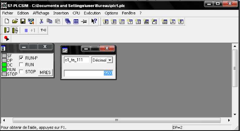
Fig. 15. Simulator S7-PLCSIMn
-
VI. Conclusion
The availability of the APS and the service continuity are major elements for the industrial performance evaluation. The designed system contains a supervisor which controls three PLC tested on a simulation station. This study was done in a petrochemical central (GP2Z) with collaboration with engineers and operators working at this central.
The program development of this system has required three Petri nets models. We have encountered a difficulty to obtain these formal models directly from the study of PLC functioning. For this reason we have firstly used a semi-formal UML model where translation rules are applied. We simulated the detection and the prevention of crash fatal error at the PLC, represented by the dysfunctioning of the power block. With these tests, we noted that the supervisor predicts this error and reacts by ordering the PLC2 to replace the PLC1. The PLC2
selection is based on a probabilistic study undertaken by the supervisor after computing the probability of wellfunctioning of each PLC. This experimentation can be generalized to other measured variables connected with each PLC components, to make sure that the supervisor can predict any anomaly and reacting to all situations (normal, degraded, failed) in replacing failed PLC by other to ensure continuity of installations.
The advantage of the designed supervision system is in offering a global vision of functioning of all system by predicting the occurrence of stop functioning. This solution also takes into account the not starting up problem of the Standby PLC for various reasons. In future work, we can include other performance parameters, and then improve the computed probability formula.
Acknowledgment
This research is supported by GP2Z-SONATRACH Company, Oran, Algeria. Thanks to the collaboration of automatic team and instrumentalists who give us ideal environment to carry out our research.
References Supervision Architecture Design for Programmer Logical Controller Including Crash Mode
- V. Carré-Ménétrier and A. Tajer, ‘Elaboration of Distributed Optimal Controller for Manufacturing Systems through Synthesis Approach’, International Conference on Communication, Computing and Control Applications (CCCA'11), IEEE, Hammamet, Tunisia, mars 2011.
- R. Roussel and J. J. Lessage. ‘Algebraic Synthesis of Controllers despite Inconsistencies in Specifications’. In Proceedings of 11th International Workshop on Discrete Event Systems (WODES’2012), Guadalajara, Mexico, 2012.
- F. Z. Bennani, L. Sekhri and H. Haffaf. ‘Conception d’une Architecture de Supervision des Automates Programmables Industriels. 9éme Journées Scientifiques et Techniques (JST9), Sonatrach. April 8-10, 2013, Oran, Algeria.
- A. Tajer and A. Philippot. ‘Decentralized Implementation Approach of Control Synthesis of Manufacturing Systems’, 2nd International Conference on Multimedia Computing and Systems (ICMCS'11), IEEE, Ouarzazate, Morocco, April 2011.
- R. Alur and D. L. Dill. ‘A Theory of Timed Automata’, Theoretical Computer Science, Vol. 126, 2, pp. 183-235, 1994.
- L. Fray and Y Litz. ‘Formal Methods in PLC Programming’. IEEE International Conference on Systems, Man and Cybernetics, vol. 4, pages 2431-2436, 2000.
- O. Gourcuf, De Smet and J.M. Faure. ‘Efficient Representation for Formal Verification of PLC Program’. In Proceedings of 8th International Workshop on Discrete Event Systems (WODES’06), pages 182-187, Ann Arbor, USA, July 2006.
- H. Laroux and M. Roussel. ‘Algebraic Synthesis of Logical Controllers with Optimization Criteria’. 6th International Workshop on Verification and Evaluation of Computer and Communication Systems (VECoS 2012), CNAM, Paris, France, August 27-28, 2012.
- U. Sanne and S. Gonzalez. ’UML Modeling and Formal Verification of Secure Group Communication Protocols’. 2nd IEEE International workshop UML and Formal Methods (UMF & FM'09), Rio de Janeiro (Brazil). December 2009.
- V. Carré-Ménétrier,, N. Hagebell and J. Zaytoon. ‘Methods and Tools for the Synthesis of an Optimal Control Implementation for Grafcet’. Journal Européen des Systèmes Automatisés, vol. 33, No. 8-9, November 1999.
- A. Philippot, ‘Survey on Diagnosis of a Pick and Place Benchmark - Special Session on Diagnosis of Discrete Event Systems: Application on a Benchmark’, 3rd International Workshop on Dependable Control of Discrete Systems (DCDS'11), pp. 27-30, IEEE, Saarbrücken, Germany, june 2011.
- L. Sekhri, A.K.A. Toguyeni and E. Craye. Surveillabilité d’un Système Automatisé de Production Modélisé par un Graphe Fonctionnel (2004), Journal Européen des Systèmes Automatisés (JESA), vol. 38, N° 3-4, pp. 243-268, October, ISSN 1269-6935.
- A.K.A. Toguyéni, E. Craye, and Sekhri, L. ‘Study of the Diagnosability of Automated Production Systems Based on Functional Graphs. Mathematics and Computers in Simulation, vol. 70, issues 5-6, 24, pp. 377-393, Elsevier, February, 2006.
- M. Daigle, Roychoudhury, I., Biswas, G. and Koutsoukos, X. ‘Efficient simulation of component-based hybrid models represented as hybrid bond graphs’. Technical Report ISIS-06-712, Institute for software integrated Systems, Vanderbi University, Nashville, USA, 2006.
- P. Gawthrop and B. Geraint, ‘Bond Graph Modeling’, IEEE Control Systems Magazine, vol. 27, 2007.
- R. David and H. Alla. ‘Discrete, Continuous and Hybrid Petri Nets’, Springer, 2005.
- R. Hakiki and L. Sekhri. ‘Hybrid Petri Nets Based Approach For Analyzing Complex Dynamic Systems’. First IEEE International Conference on Machine and Web Intelligence (ICMWI’2010). 3-5 October, Algiers, Algeria, 2010.
- B. Brandin and W. M. Wonham. ‘Supervisory Control of Timed Discrete Event Systems’, IEEE Transactions on Automatic Control, vol.39, 2, pp. 329-341, February, 1994.
- A. Gouin and J.L. Ferier,. ‘Modeling and Supervisory Control of Timed Automata’, Journal Européen des Systèmes automatisés, vol. 33, No. 8-9, November, MSR’99, pp-1093-1110, 1999.
- L. Guan-Chun, ‘Control and Automation’, Universal Journal, September 2013.
- A.T. Sava, A.T. and H. Alla, ‘A Control Synthesis Approach for Time Discrete Event Systems’. Mathematics and Computers in Simulation, vol. 70, issues 5-6, 24, pp. 250-265, Elsevier, February, 2006.
- M. El Najjar, C. Smaili, F. Charpillet and D. Pomorski. “Supervision and Safety of Complex Systems”. ISTE Ltd and John Wiley & Sons. August 2012.
- A. Philippot and A. Tajer, and V. Carré-Ménétrier. ‘From Centralized to Decentralized Approach for Optimal Controller of Discrete Manufacturing Systems’. ARPN Journal of Science and Technology. November 2012.
- Technical Manual. ‘Premium Warm Standby’ . Schneider-Electric.
- Technical Review. ‘PLC Siemens S7 high availability’.
- Benani, F. Z. ‘Design of Virtual PLC’. Magister Thesis. University of Oran, Algeria, 2011.
- A. Philippot, M. Sayed Mouchaweh and V. Carré-Ménétrier. ‘Generation of candidates tree for the fault diagnosis of discrete event systems’, 2nd IFAC Workshop on Dependable Control of Discrete System, Elsevier, Control Engineering Practice. September 2011.
- W. Hettab, ‘ From UML to Petri Nets’, Journal of object technology, Zurich, Suizerland, ETH Zurich, Chair of Software Engineering, 2010.
