Systematic design of optimized pulse shape for transthoracic defibrillation

Author: Chernov Nikolay N., Korotkova Oksana I., Bezverkhii Aleksandr A.
Journal: Cardiometry @cardiometry
Section: Original research
Article in issue: 17, 2020.
Free access
In the study conducted by us previously, it was found that not only the energy of the discharge, but also the amplitude of current, the pulse duration and its shape have their significant influence on the efficacy of defibrillation. Until now, no systematic approach to the comparison of the pulse shapes effectiveness has been available. An identification of the optimal pulse parameters for defibrillation has not only theoretical aspects but also engineering details in the design implementation. In order to conduct a complete pulse optimization, required is a multidisciplinary approach to determining boundary values and searching for further ways to improve the efficiency of electropulse therapy. An understanding of the relationship between the biphasic pulse parameters and the criteria for healthcare quality can make it possible to increase the survival rate of patients with ventricular fibrillation and ventricular tachycardia. The implementation of the current stabilization system in the defibrillator allows realizing an individual selection of the pulse energy defibrillation.
Transthoracic defibrillation, biphasic pulse, current stabilization, cardiomyocytes repolarization, ventricular fibrillation
Short address: https://sciup.org/148311474
IDR: 148311474 | DOI: 10.12710/cardiometry.2020.17.3438
Text of the scientific article Systematic design of optimized pulse shape for transthoracic defibrillation
Nikolay N. Chernov, Oksana I. Korotkova, Aleksandr A. Bezverkhii. Systematic design of optimized pulse shape for transthoracic defibrillation. Cardiometry; Issue 17; November 2020; p.34-38; DOI: 10.12710/cardiometry.2020.17.3438; Available from:
When designing a biphasic defibrillation pulse, it is necessary to take into account several parameters, which will make an impact on the efficiency of electropulse therapy. The output energy is a measure of the pulse efficiency. The main directions of optimization consist in its reduction to minimize the potential damaging effects with increasing a probability of the defibrillation success. Also potentially dangerous are high peak current and high output power. The maximum charge voltage is an engineering component. All boundary conditions being equal, a higher charging voltage leads to a more efficient use of energy stored in the high-voltage capacitor and reduction of the size of the defibrillator itself. One of the key aspects is the shape and the duration of a defibrillation pulse.
An analysis and a comparison of the pulses applied in the present-day medical practice show good clinical results at a discharge energy of 120-150 Joules, but this is not a limit. There are some theoretical prerequisites for further reducing the discharge energy while maintaining the desired efficiency.
The aim of our research work is to design a method of individual dosing of the defibrillation intensity in the transthoracic defibrillator.
Materials and methods
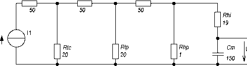
To create the electrical equivalent circuit, the layer-by-layer resistance of tissues and organs of the thorax may be thought of as resistors, connected in series in case of current passage through the tissue and in parallel in case of shunting current path. A cardiomyocyte itself can be presented as a capacitor, as the bilipid cell wall endows it with capacitive properties. Figure 1 exhibits the equivalent circuits with different levels of organization. They illustrate how current flows through resistor Rs (serial), which is generated by the internal resistors, the power supply line and the electrodes. Next the current is divided into a portion which flows over or under the skin in the form of shunt current around the thorax through Rtc (thorax) and through the thorax wall, designated by Rcw. In the region below the ribs, the current is again divided into portions, which flow around the lungs (Rlp for the parallel connection) or flow through them (Rls for the serial connection). The heart itself also provides a shunting path, which is represented by Rhp.
Rs Rew Ris
Rs2 Rs3
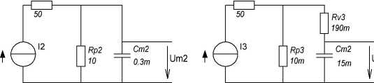
Figure 1. Three general minimum equivalent schematic circuits of current path in transthoracic defibrillation
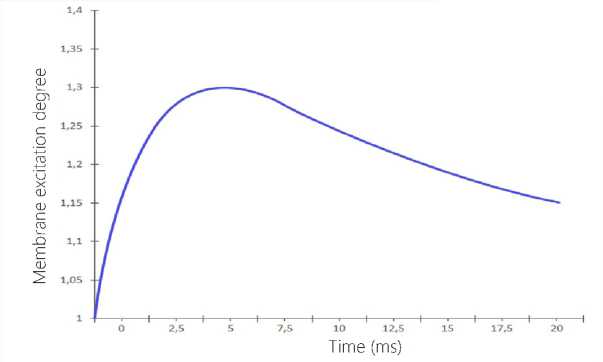
Figure 2. Relative deviation of the model is reduced to the
Weiss-Lapicque stimulation law in Figure 1 (Equation 2)
Depending on the formulated task, this equivalent schematic circuit is used with different detailed engineering options, but they are capable to be qualitatively transformed into each other. It is the case as long as the constant of time, the voltage curve and the characteristics differ only quantitatively.
the results published by Blair [8, 9] in 1932. These results are similar to those by Weiss and Lapicque [10], which have independently described the stimulation effect later. Figure 2 shows the relative excitation of the membrane as a function of the pulse duration depending on the intensity according to Weiss and Lapicque:
τ=(Rhi+Rhp)∙Cm (1)
I(T
Impuls
Rheobase
∙(1+τ
Membrane
/T
Impuls
)
In these models, the membrane excitation must experience a permanent voltage oscillation before the actuation. In any case, the absolute threshold values cannot be determined. An individual resistance is an intrinsic variable featuring a patient. However, measurements in dogs showed that about 3% [2] - 4% [3] of the defibrillator current effectively flow through the heart. In humans, because of the planar geometry of the thorax, it is assumed that the proportion of the effective current should be greater. The percentage slightly depends on the patient's constitution. There are at least some publications stating that the current strength is a quite comparable stimulation parameter [4, 5]. Therefore, only the following parallel RC model is considered for the following reasons. This very simplified equivalent basic circuit already provides some important findings: the existence of rheobase can be explained with the use of the equivalent basic circuit mentioned above. As long as the current flowing through extracellular resistor Rp is insufficient, the voltage at the Cm membrane would never be sufficient for the stimulus threshold. The greater the current, the shorter the time of the membrane capacitance charging through the intracellular resistance. Therefore, the stimulus threshold is reached earlier.
The threshold stimulation values, which are determined with the help of these models, correspond to
As seen from the above Figure, the maximum deviation of 30% may seem to be very large, but considering the fact that the initial data for the model cannot be determined, and in the analysis, we carried out before [1], most modern high pulses have a pulse duration ranging from 3 to 20 ms, then this deviation cannot be viewed as so much significant.
With the use of the above equivalent circuits, designed have been several pulses, which are extensively used in practice [8,9,10]; their effectiveness has been confirmed by clinical tests and the vast experience in the application of the external defibrillators in practice [11,12,13]. The main problem of the equivalent circuits shown in Figure 1 is that the specific values of all their units cannot be properly identified, and, consequently, it is impossible to determine the effect produced by certain parameters of the patient such as age, weight, height, etc. In most cases, these data were selected either empirically or taken as a constant and not considered in the calculations. In the reference literature, the 2 - 4 ms interval is often mentioned as the optimal pulse duration [14,15,16]. Our study showed that the most effective pulses had durations of 4-6 ms [1]. In the calculations with the use of Equation 1, the optimal time is 3 - 6 ms.
The biphasic truncated exponential pulse is most extensively employed now. Returning to the analysis of the equivalent circuit in Figure 1 and basing on the
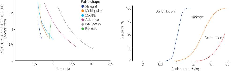
Figure 3. Diagram of the relationship between the cardiomyocyte maximum response and the time for patients’ bodies with an impedance from 25Ohm to 175 Ohm
Figure 4. An effect of different pulse intensity on the success of defibrillation and damage potential findings made by Irnich in [17,18], we can come to some simple conclusions: at a current intensity below the rheobase no effective stimulation occurs, therefore, that portion of an exponentially decaying pulse, which is below this level, is of no concern, i.e. an increase in the pulse duration will not lead to the charging of the capacitor in the model and to stimulation of a cardiomyocyte in the heart.
In the previous research work [1] pertaining to a comparison of the existing pulse waveforms, analyzed was a relationship between the pulse duration and the patient’s body impedance. The generally accepted range of allowable values for defibrillation covers an interval from 25 to 175 Ohm, and Figure 3 herein gives a summary diagram of various pulses. The diagram displays the relationship between the maximum excitation and the time for different impedance values in patients’ bodies. The diagram exhibits that the highest membrane excitation is identified at the patient’s body impedance of 25 Ohm, and the lowest at 175 Ohm, respectively.
The main goal of defibrillation is to achieve the rheobase by all cardiomyocytes in the heart, for this purpose it is necessary to maintain a certain level of the current required to reach the threshold of stimulation during the whole pulse. As we see from the diagram, the "Straight" and “Biphasic" pulses are best suitable to achieve this goal. This diagram has a substantially rectangular shape and different current amplitude for different impedances. This has been evidenced in an experiment with a biphasic defibrillator by J.C. Schuder in 1964. Defibrillating a dog, he succeeded in demonstrating that the "rectangular or 36 | Cardiometry | Issue 17. November 2020
square pulses with a constant current strength" produced the greatest efficiency effect of defibrillation [19]. However, such pulse shapes were very difficult to implement at that time, so that the above research work was purely experimental. The defibrillator was capable of delivering almost any shape of pulse when controlled by the current. The high-voltage switch was implemented with 11 power lights and could supply up to 20A with an impedance up to 60 Ohm. Two charging capacitors of 1000 µF were charged to 2 kV that corresponded to the energy storage of 4000 J. At that time this sort of design versions was very expensive for implementation and practical application. Also the engineering capabilities of electronics at that time did not allow starting commercial production, so the results of that research work had no practical application and have been in large measure forgotten.
The practical importance of an accurate dosing is described in detail by Tacker [20]. Figure 4 offers a diagram of the dependence of the defibrillation success on the current strength. The curves show that there is an area, where the curves of the successful defibrillation and the damage potential overlap, i.e. each attempt with the sufficient current strength inevitably leads to damage of cardiomyocytes. Besides this possible damage caused by this kind of the defibrillation pulse, there is another problem available: the problem of accumulation. Several sequential pulses produce an accumulated damage potential [21]. To avoid this unfavorable event, a minute interval between each defibrillation was included into the Guidelines for resuscitation in 2005.
Results and Discussions
In our previous work when analyzing the pulse shapes it was found that the peak current for low impedance patients may reach 90 A. On the other hand, patients with high impedance the peak current value did not reach 18 A. Gold and Schuder proved that a high probability of defibrillation success is possible only in a certain range of current and time [15]. Koning [22] used the Weiss-Lapicque law of stimulation and derived the following equation for the optimum pulse:
I(τ)=IRheobase∙(1+τChronaxie/τ) (3)
Taking into account the results obtained by Kroll [12], where the rheobase is approximately 0.3 A, using equation 3, we obtain the 4 ms time for each phase. Considering that only 4% of the current leads to an efficient defibrillation, in the first phase of the biphasic pulse, with pulse duration of 6 ms, the average current of 14A is required [4].
Since the average current strength has been chosen as the main parameter determining the dosing of defibrillation discharge, it is used as the reference measure. In the first phase, the constant average current was 15 A during 6 ms, and, after a switching interruption of 300 ms, a negative phase with a current of 10 A within 3 ms follows.
According to Chapman [20], only 15% of the human individuals have an impedance value above 125 Ohm, so the impedance dispersion of the patient for modeling is established to be in the range from 25 Ohm to 125 Ohm. The model response of the pulse at 125 Ohm reaches the threshold defibrillation energy of 208 J, so these results are comparable with the existing signals of rectilinear shape, the efficiency of which has been confirmed experimentally, especially in patients showing high impedance level of their bodies.
The second phase has also a rectangular shape, but its current strength is smaller, and its duration is shorter. There are also some studies, which compare different variants of the second phase, but they all have approximately the same result in a wide range of tolerances [21].
Conclusions
The aim of this research work is to develop a method of individual dosing of the defibrillation intensity for an automated external defibrillator.
This aim can be attained only in the case of breaking the conventional energy dose paradigm. The most suitable fresh approach is to determine the average current (I) and the charge (Q) calculated as a function I (t) for the description of the defibrillation pulse in transthoracic defibrillation.
So, the defibrillation pulse defined in such a way takes into account the patient's constitution peculiarities as against the classical definition of energy. This means that the effective defibrillation can be achieved with the first pulse. Thus it is possible to avoid both potential overdoses and harmful accumulated damage due to increased number of defibrillation discharges and the associated loss of time during resuscitation.
Statement on ethical issues
Research involving people and/or animals is in full compliance with current national and international ethical standards.
Conflict of interest
None declared.
Author contributions
The authors read the ICMJE criteria for authorship and approved the final manuscript.
References Systematic design of optimized pulse shape for transthoracic defibrillation
- Chernov N, Bezverkhii A, Timoshenko V. Cardi¬ometry; May 2020;16:69-74; DOI: 10.12710/cardiom-etry.2020.16.6974.
- Lerman BB, Deale OC. Relation between transcar¬diac and transthoracic current during defibrillation in humans. Circ. Res. Dec 1990;67:1420-6.
- Malmivuo JJ, Plonsey R. Bioelectromagnetism. Ox¬fort University Press, 1995.
- Bourland JD, et al. Comparative efficacy of damped sine wave and square wave current for transchest ventricular defibrillation in animals. Med Instrum. 1978;12(1):42-5.
- Wesley RC, Morgan D, Zimmerman D. Limitations of the countershock dose response: a study of trans-thoracic current. Pacing Clin Electrophysiol. Nov 1991;14:1855-9.
- Blair HA. On the Intensity-Time Relations for Stimulation by Electric Currents II. J. Gen. Physiol. Jul 1932;15:709-29.
- Weiss G. Sur la possibilite de rendre comparables entre eux les appareils servant a l t'exitation electrique. Arch Ital Biol. 1901;35:413-46.
- Swerdlow CD, et al. Application of models of de¬fibrillation to human defibrillation data: implications for optimizing implantable defibrillator capacitance. Circulation. Nov 1997;96:2813-22.
- Charbonnier F. External defibrillators and emer¬gency external pacemakers. Proceedings of the IEEE. 1996;84:487-99.
- Gold JH, Schuder JC, Stoeckle H. Contour graph for relating per cent success in achieving ventricular defibrillation to duration, current, and energy content of shock. Am Heart J. Aug 1979;98:207-12.
- Jones J, Jones R. Determination of safety factor for defibrillator waveforms in cultured heart cells. Am J Physiol. 1982;242:H662-70.
- Niebauer MJ, et al. Efficacy and Safety of Defibril¬lation with Rectangular Waves of 2 to 20-milliseconds Duration. Critical Care Medicine. 1983;11:95-8.
- Irnich W. The fundamental law of electrostimula¬tion and its application to defibrillation. Pacing Clin Electrophysiol. Nov 1990;13:1433-47.
- Irnich W. Optimal truncation of defibrillation puls¬es. Pacing Clin Electrophysiol. Jun 1995;18:673-88.
- Schuder JC, Stoeckle H, Dolan AM. Transthoracic Ventricular Defibrillation with Squarewave Stimuli: One-Half Cycle, One Cycle, and Multicycle Wave¬forms. Circ Res. 1964;15(3):258-64.
- Tacker W. Defibrillation of the Heart: ICDs, AEDs, and Manual. St. Louis: Mosby – YearBook, 10, 1993.
- Wilson CM, et al. Death and Damage Caused by Multiple Direct Current Shocks: Studies in an Animal Model. European Heart Journal. 1988;9(11):1257-65.
- Koning G, et al. Amplitude-duration relation for direct ventricular defibrillation with rectangular cur¬rent pulses. Med Biol Eng. May 1975;13:388-95.
- Ayati S, Lopin ML. Electrotherapy Current Wave¬form. WO 98/26841, June 25,1998.
- Chapman LF. Defibrillation impedance: a current affair? Does choice of defibrillator waveform affect outcome for high-impedance patients? Insync, 1997. Magazine of Physio-Control Corporation.
- Schuder JC, Stoeckle H, Dolan AM. Transthoracic Ventricular Deffibrillation with Squarewave Stimuli: One-Half Cycle, One Cycle, and Multicycle Wave¬forms. Circ Res. 1964;15(3):258-64.
