Technological justification of constructive solutions for railway roadbed on permafrost soils using an expert system

Author: Shepitko T.V., Polyansky A.V., Artyushenko I.A., Nozdrachev A.S.
Journal: Nanotechnologies in Construction: A Scientific Internet-Journal @nanobuild-en
Section: System solutions for technological problems
Article in issue: 6 Vol.17, 2025.
Free access
Introduction. The theoretical foundations and practical aspects of implementing technological justification for design concept of railway roadbed on permafrost soils using an expert system are considered. Railway construction in permafrost regions requires specific design solutions and technologies due to complex natural and climatic conditions, geological process dynamics, and the need to coordinate multiple project participants. In such conditions, the development of efficient technological processes, including the construction of railway roadbed, becomes crucial and is achieved through the implementation of an engineering-intelligent subsystem for technical support. The aim of this study is to develop a methodology that integrates intelligent technologies into the processes of designing railway roadbed on permafrost soils to achieve an optimal balance between timelines, cost, resources, and operational reliability of the structure. To this end, an analysis of the technological features of construction in the cryolithozone was conducted, including site-specific localization, resource intensity of processes, variability of design parameters, and year-round work operations. Methods and Materials. The methodology includes the decomposition of the railway roadbed into constructional elements using graph models that formalize the interconnections between subsystems, as well as the development of an expert system based on a production knowledge model for automating the generation of construction work nomenclature. The results of the decomposition and generation of construction work nomenclature form the basis for optimizing the technological process, scheduling, and the development of work production projects. Results and Discussion. Based on the results of the theoretical research, the article explores the possibilities of applying a specially developed experimental software module for the technological justification of design solutions for railway roadbed on permafrost soils. The practical significance of the study is confirmed by the implementation of experimental software modules, including those incorporating intelligent components. This enables a transition from traditional variant-based design to adaptive real-time solutions, minimizing errors and time expenditures. Conclusion. The results of the work demonstrate the potential of intelligent information systems for railway construction in permafrost regions, where process formalization and decision automation play a key role in achieving sustainable development in the industry.
Technological process, railway construction, railway roadbed, cryolithozone, permafrost soil, work nomenclature, artificial intelligence methods, expert system, knowledge base
Short address: https://sciup.org/142246531
IDR: 142246531 | DOI: 10.15828/2075-8545-2025-17-6-760-774
Text of the scientific article Technological justification of constructive solutions for railway roadbed on permafrost soils using an expert system
Original article
Шепитько Т.В., Полянский А.В., Артюшенко И.А., Ноздрачёв А.С. Технологическое обоснование конструктивных решений железнодорожного земляного полотна на многолетнемерзлых грунтах с применением экспертной системы. Нанотехнологии в строительстве. 2025;17(6):760–774. – EDN: TBQTFA.
The integration of artificial intelligence into the resolution of organizational and technological challenges in railway construction (RWC) opens new opportunities for improving the efficiency of construction operations. The application of artificial intelligence methods and tools has the potential to significantly transform the methodology of designing and implementing railway infrastructure projects, particularly in areas with complex natural, climatic, and engineering-geological conditions. Among the key areas of impact are [1, 2]:
-
1. analysis of data from completed projects to plan time and financial parameters while considering changing work production conditions;
-
2. optimization of the allocation of construction resources (labor and equipment) across construction sites;
-
3. evaluation of the constructability of design solutions;
-
4. identification of optimal variants of technological processes.
The focus on intelligent methods is driven by the specific nature of RWC technological tasks, which often belong to the class of complex systems with fuzzy boundaries. Such problems cannot be adequately described using traditional mathematics and require innovative approaches. In particular, the formalization of the process of technologically justifying design solutions, which relies on intuitive techniques and the developer’s experiential knowledge of the organizational and technological documentation (OTD) [2, 3], encounters the vastness of the search space. Despite the discreteness of the solution set, their combinatorial diversity renders purely computational methods inadequate [4–7].
Artificial intelligence tools, which possess the ability to learn and adapt, become a key instrument in such situations. The fundamental difference between their approach and analytical methods lies in incorporating the expertise and professional knowledge of specialists into algorithmic solutions. This provides WTD developers not only the ability to preserve but also to systematize accumulated experience, leading to increased reliability of decisions and reduced decision-making time [2, 8].
The implementation of such systems facilitates the transition from routine procedures to the development of adaptive models capable of accounting for nonlinear relationships between technical and economic parameters, environmental dynamics, and organizational constraints. This, in turn, creates a foundation for developing flexible and efficient technological solutions for RWC in challenging conditions.
METHODS AND MATERIALS
The study of the application of artificial intelligence in the technological design of RWC in challenging con- ditions has contributed to the development of advanced schemes for creating OTD. Fig. 1 presents a structural diagram of intelligent design for the technological process of constructing a railway roadbed (RR) on permafrost soils (PS). According to the scheme presented in this work (Fig. 1), stages 1, 2, 3, 6, and 8 implement computational procedures, while stages 4, 5, and 7 require algorithms that combine mathematical calculations with logical operations to analyze interdependencies between modules. The latter, acting as a link between computational blocks, confirm the need to create a comprehensive automated platform that integrates traditional calculation methods with intelligent components, ensuring systematic coordination of the stages of technologically justifying design solutions for RR on PS [2, 7, 8].
In this work, the solution to the problems of technologically justifying design solutions for RS on PS, covering stages 3 and 4. It should be noted that the construction process of RS under such conditions is characterized by its duration, high resource intensity, and the need to coordinate all participants in the construction process. These factors determine the key technological features [9]:
-
1. territorial localization of RS;
-
2. resource mobility (movement of workers and equipment, transportation of materials, assembly/disassembly of equipment and structures);
-
3. variability of parameters (diversity of forms, sizes, and operational characteristics);
-
4. specifics of year-round construction in complex (adverse) natural and climatic conditions.
To account for the aforementioned features, it is proposed to break down the technological process of RS construction into simple technological processes (STP), performed on individual work zones with the involvement of qualified teams. Accounting for these technological features requires a systematic approach to work planning, ensuring synchronization in time and space to achieve quality, safety, and cost-effectiveness.
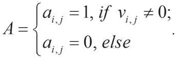
The first stage of technological justification involves analyzing the structure of RR on PS (Fig. 1, stage 3). For this purpose, a procedure for decomposing the object into constituent elements has been developed (Fig. 2), allowing RR to be considered as a hierarchical system with defined interconnections between subsystems. The formation of an information model of RR on PS includes the description of technical and structural parameters for the subsequent automation of the decomposition procedure.
To perform the decomposition of the RS, a graph model of constructional solution (CS) is used, represented by a directed graph (digraph) G R C S S (Fig. 3). The vertices of the graph correspond to constructional elements (CE), and the edges represent technological dependencies between them. The implementation of the RS decomposition procedure on PS in an automated mode assumes the representation of the digraph in matrix form. For this
SYSTEM SOLUTIONS FOR TECHNOLOGICAL PROBLEMS
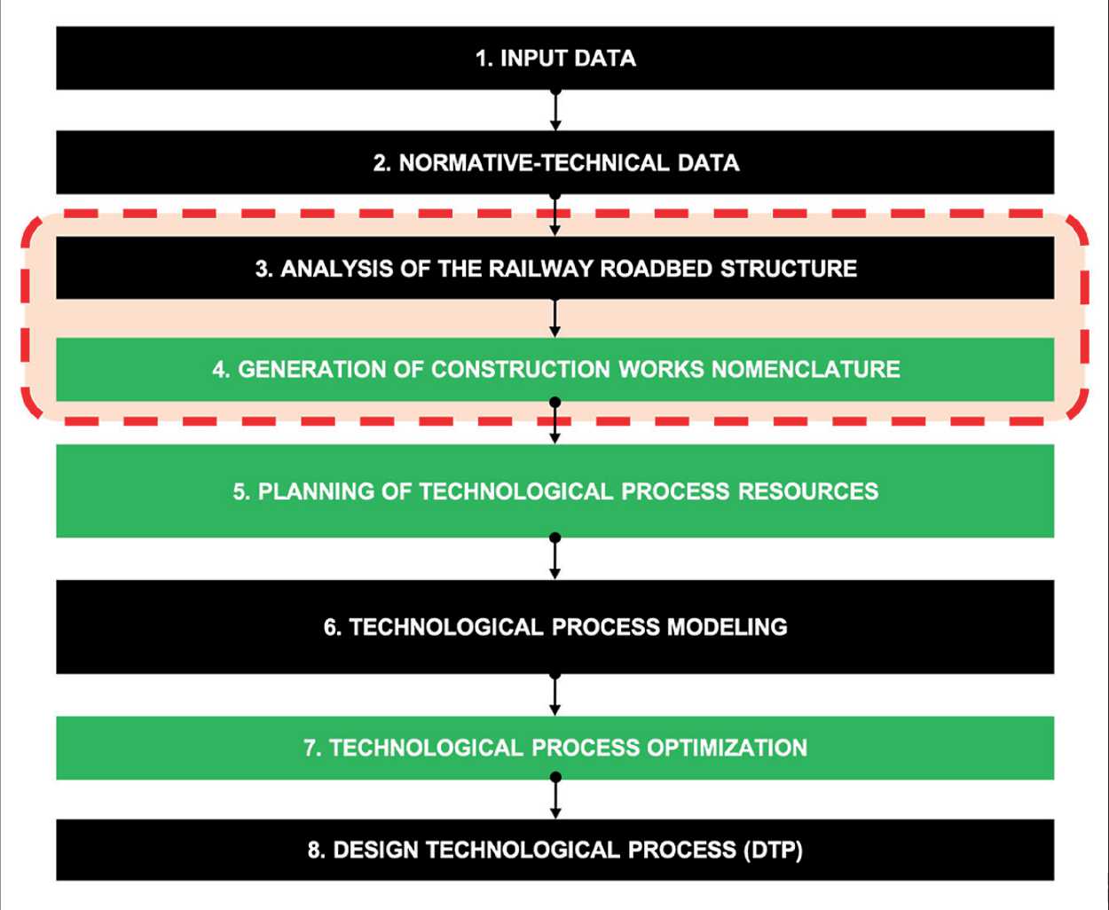
Fig. 1. Structural diagram of intelligent design for the technological process of constructing a railway roadbed on permafrost soils
purpose, an adjacency matrix A = || ai , j || can be used, which formalizes the vertices of the digraph ( ai and aj ) and the connections (edges) between them ( vi , j ), which can be expressed as:
This reduces the problem to finding the optimal path in the digraph, where the constructional elements and the connections between them formalize the model of the constructional scheme of the RS on PS:
'%ps={CE,SL} ,
где CE – constructional elements, SL – structural line (Fig. 4).
The graph model developed in the previous stage serves as the foundation for implementing the second stage of the technological justification of the RS on PS – the automated generation of the nomenclature of construction works (NCW) using an expert system (Fig. 1, Stage 4). The use of a graph structure, specifically structured technological relationships between constructional elements, ensures the formalization and systematization of data prior to the generation of the work list [2, 7].
It is important to note that the formation of the nomenclature of construction works, which plays a key role in developing technological processes and creating OTD, is characterized by high complexity and vulnerability to errors. This is primarily due to limited available information, time constraints, and the need to analyze extensive normative and technical data. The consequences of such errors are critical to the economic and technical safety of construction operations [12–20].
SYSTEM SOLUTIONS FOR TECHNOLOGICAL PROBLEMS
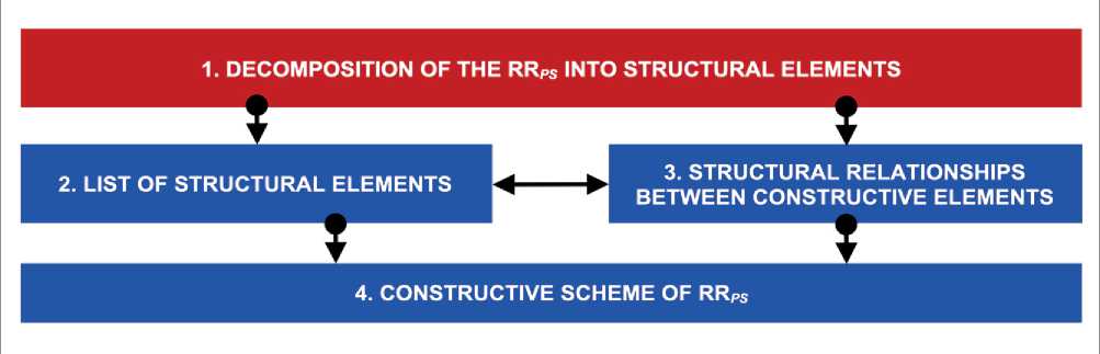
Fig. 2. Decomposition of the railway roadbed on permafrost soils into constructional elements
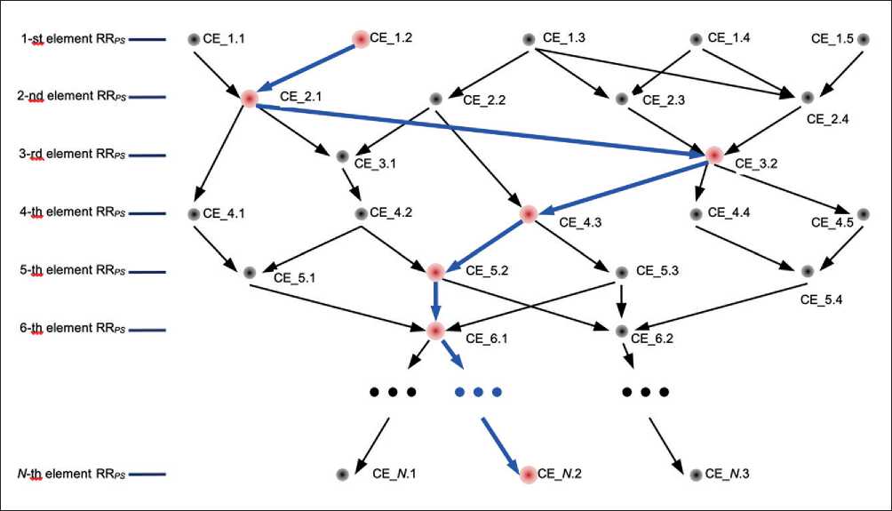
Fig. 3. Fragment of the general graph model of the railway roadbed on permafrost soils with the selected sequence of constructional elements (CE)
The intellectualization of forming the nomenclature of construction works through an expert system aims to minimize errors and improve the efficiency of developing technological processes.
To address these challenges, the use of productionbased expert systems (ES) has been proposed, combining formalized analytical models with heuristic methods. This approach allows for the implementation of difficult-to-formalize stages of developing technological processes in an intelligent mode, enhances the objectivity of decisionmaking, and reduces time costs. Additionally, an important advantage of expert systems is their ability to accumulate, store, and modify knowledge, minimizing subjective factors that influence decision-making. Unlike traditional methods, they provide a systematic analysis of task specifics, which is critically important when working with RS on PS, where parameters exhibit variability and dynamics [12–20].
For the implementation of the intelligent operation mode, a production-based ES model was chosen, based on rules of the form “IF (fact), THEN (action).” This model offers the following advantages [2, 5–7, 11, 21, 22]: • clarity – due to the semantic transparency of the rules; • adaptability – suitability for discrete processes typical of railway construction (RWC);
SYSTEM SOLUTIONS FOR TECHNOLOGICAL PROBLEMS
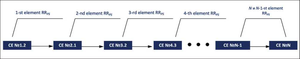
Fig. 4. Graph model of the structural scheme of the railway roadbed on permafrost soils: CE – constructional element
-
• modularity – the ability to dynamically expand the knowledge base without compromising system integrity.
The knowledge base of the ES is the main component, allowing knowledge to be formalized in the form of production rules:
{γ ⇒δ, (3)
где γ – antecedents (facts), δ – consequent (action). The logical inference mechanism (Fig. 5) ensures the search for solutions by analyzing the correspondence of antecedents to the current state of the subject domain (in this case: information, data, constraints, and possibilities for constructing RS under PS conditions). To optimize performance when dealing with a large number of rules, a backward-chaining inference strategy is applied, start- ing from the target fact, which accelerates the decisionmaking process [2, 7, 11].
Figure 5 illustrates the operation scheme of a production-based expert system, including a knowledge base (repository of production rules) and a logical inference mechanism (module implementing solution search).
The procedure for generation of NCW consists of three stages [2, 7]:
-
1. interactive interaction - obtaining input data from the developer of the OTD (the system analyzes the design features of the RS, including unique requirements for materials, geometric parameters, and interconnections of elements, dictated by the complex conditions of PS);
-
2. data processing – classification of construction works based on their association with constructional elements (CE) of the RS using an expert system (ES) (logical principles of developing the technological process
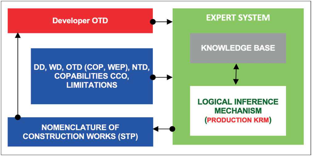
Fig. 5. Diagram of the expert system operation: OTD – organizational and technological documentation; PD – design documentation; WD – working documentation; COP – construction organization project; WEP – work execution project; NTD – normative and technical documentation; CCO – construction (contracting) organization; STP – simple technological process; KRM – knowledge representation model
-
3. result generation – creation of a structured list of construction works (at the level of STP) with an indication of their interconnections (resource provision of works is considered, particularly volumes, scope, duration, and technical capabilities of the contracting organization, which is critically important for adapting technological processes to real production conditions).
SYSTEM SOLUTIONS FOR TECHNOLOGICAL PROBLEMS are considered, including the use of work sequences tied to individual constructional elements, followed by their integration into a unified system);
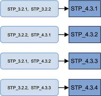
Thus, the expert system analyzes the graph model of the RS constructional scheme (Fig. 4), identifying STP and their technological connections. The result is a nomenclature of construction works, structured into N layers, each corresponding to a specific constructional element (Fig. 6). This approach ensures visual transparency of the generation of NCW, allowing the determination of preceding stages for each STP and synchronizing their execution.
The application of ES contributes to:
-
• automation of routine stages (e.g., work classification);
-
• accelerating decision-making through the integration of technological patterns;
-
• formation of a structured nomenclature of construction works, including resource characteristics of STP, which becomes the basis for scheduling [12–20].
The implementation of expert systems in the technological justification of design solutions for RS) on PS not only formalizes complex technological processes but also lays the groundwork for their further evolution within the framework of digital transformation in railway construction.
Despite the limitations of fully replacing the developer of OTD (human factor), the ES becomes a tool that minimizes errors and optimizes time costs. This enables a transition from variant-based design to intelligent support of RWC processes, enhancing the level of automation and reliability of technological solutions.
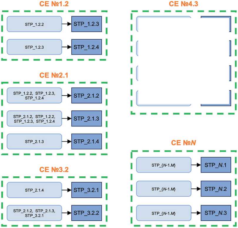
Fig. 6. Interconnections between simple technological processes (STP) linked to constructional elements (CE)
SYSTEM SOLUTIONS FOR TECHNOLOGICAL PROBLEMS
RESULTS AND DISCUSSION
The practical implementation of the methodology for technologically justifying design solutions for RS on PS is carried out through the use of two experimental software modules (ESM), developed to automate the previously discussed stages (3 and 4, see Fig. 1):
-
1) “Construction-M” – an environment for the automated decomposition of RS into individual constructional elements;
-
2) “Techstructure-M” – an environment providing technological justification, including:
-
• interaction shell – an interface for inputting and adjusting data;
-
• knowledge base “Technology” – a repository of production rules formalizing technological dependencies;
-
• logical inference mechanism – a module implementing algorithms for finding optimal solutions based on graph models;
-
• database “Techstructure-M” – a repository storing the results of generating the nomenclature of works and parameters of constructional elements.
Below, an example of applying the two ESMs for the technological justification of an RS embankment on PS is considered.
Fig. 7 shows the cross-sectional profile of an RS embankment on PS (in a flooding-prone area), which is analyzed using the ESM.
First, the “Construction-M” module is used (Fig. 8). During its operation, the following is performed:
-
• input of initial data: geometric parameters of the embankment, soil characteristics, material properties, and constructional elements;
-
• automated decomposition of the railway roadbed (RR) into constructional elements using a graph model, where vertices correspond to elements, and edges represent – technological relationships.
The result of work ESM is the identification of key constructional elements of the embankment in the flood- ing-prone area, which enables the formalization of their interactions and the determination of requirements for technological processes.
Table 1 presents a list of the embankment's constructional elements (in the flooding-prone area) along with their characteristics, obtained using the ESM “Construction-M.”
Each structural element of the embankment defines a comprehensive technological process (CTP). Accordingly, for the obtained list of constructional elements, six CTPs are provided:
-
1) «Foundation preparation»;
-
2) «Installation of filtering layers»;
-
3) “Construction of the lower part of the embankment body”;
-
4) “Construction of the upper part of the embankment body”;
-
5) “Construction of the main platform”;
-
6) «Slope reinforcement.»
Next, the procedure for generation of NCW at the level of simple technological processes (STP) is carried out using the ESM “Techstructure-M.”
Launching the ESM “Techstructure-M” initiates interactive work between the developer of OTD and the expert system. The module’s functionality ensures the collection and analysis of parameters of the RS constructional elements on PS, including material characteristics and work production conditions. Additionally, the module interface allows for adjusting input data, working with the knowledge base (adding, removing, or modifying production rules).
The expert system’s knowledge base is implemented based on production rules that formalize cause-and-effect relationships between the RS constructional elements and technological processes specific to RWC under PS conditions. The knowledge base is organized as a hierarchical relational structure created using the MS Access database management system. Within this architecture, production rules are formalized through five interconnected tables, ensuring logical integrity and structured knowledge [2, 7].
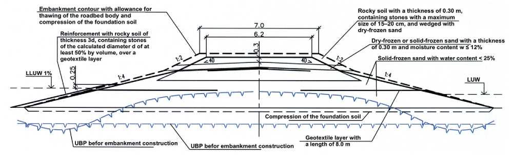
Fig. 7. Cross-sectional profile of the railway roadbed embankment on permafrost soil (in a flooding-prone area)
SYSTEM SOLUTIONS FOR TECHNOLOGICAL PROBLEMS
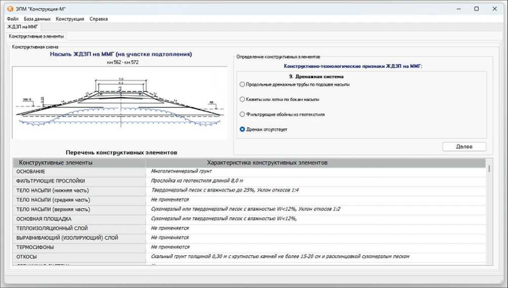
Fig. 8. Fragment of the operation of the ESM "Construction-M"
Table 1. Constructional elements of the RS embankment on PS (in a flooding-prone area) and their characteristics
|
Constructional element |
Material |
Characteristic |
|
CE №1. «FOUNDATION» |
soil |
permafrost |
|
CE №2. «FILTERING LAYERS» |
geotextile |
Layer with a length of 8.0 m |
|
CE №3. «EMBANKMENT BODY (lower part)» |
soil |
Solid-frozen sand with woter content W < 25%; Slope gradient: 1:4 |
|
CE №4. «EMBANKMENT BODY (upper part)» |
soil |
Dry-frozen or solid-frozen sand with woter content W ≤ 12%; Slope gradient: 1:2 |
|
CE №5. «MAIN PLATFORM» |
soil |
Dry-frozen or solid-frozen sand with woter content W ≤ 12%; |
|
CE №6. «SLOPES» |
soil |
Rocky soil – thickness 0.30 m, with stone size not exceeding 15–20 cm, and wedged with dry-frozen sand |
This approach to working with rules allows for adaptive updates to the knowledge base by incorporating data obtained during the practical determination of the NCW for RS on PS. The use of a relational model ensures not only storage but also efficient searching of production rules in multitasking environments, minimizing data redundancy and accelerating logical inference processes.
An advantage of the chosen architecture is the ability to dynamically expand the knowledge base without compromising system integrity. This ensures adaptability to new conditions, expanding its functionality through the accumulation and structuring of experience. A key feature is the dynamic updating of the knowledge base, which allows for considering changes in normative and technical requirements and improving decision-making algorithms based on the analysis of real technological solutions [2, 7].
The use of a relational DBMS ensures not only storage but also efficient searching of production rules during system operation. Each table in the database is responsible for a specific aspect of knowledge: from describing constructional elements to connections between them and
SYSTEM SOLUTIONS FOR TECHNOLOGICAL PROBLEMS corresponding technological processes. This minimizes data redundancy and accelerates logical inference processes during generation of NCW generation.
The developed knowledge base structure ensures high system flexibility, which is critically important for solving problems under complex geotechnical and climatic parameters of PS. Its modularity allows for changes to individual rules without compromising the integrity of the entire system, which is especially relevant for the continuous improvement of technological solutions in RWC [2, 7].
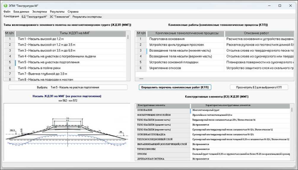
The interface of the ESM “Techstructure-M” includes the following modes [2, 7]:
-
1) “Structure” – allows working with types of RS on PS, the list of RS constructional elements on PS generated in the ESM “Construction-M,” and comprehensive work (CTP) (Fig. 9);
-
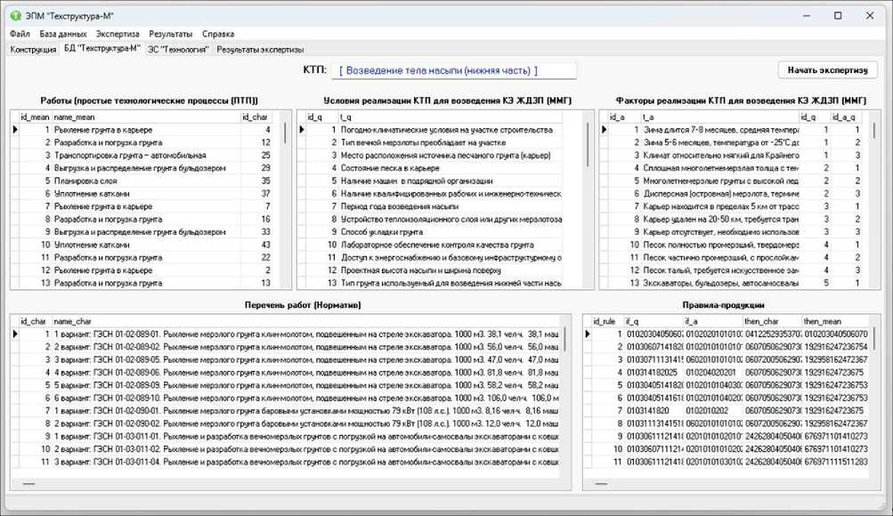
2) “DB Techstructure-M” – allows inputting, modifying, accumulating, and viewing: lists of STPs; parameters (constructional elements) of RS on PS; implementation conditions of CTP for constructing an RS structural element on PS; implementation factors of CTP for constructing an RS structural element on PS; productiontype rules (Fig. 10), which are represented by a tuple containing four components in encoded form:
{{Conditions for CTP implementation} => {Factors for CTP implementation} → {Works (STP)} ↔ {Works (normative)}};
-
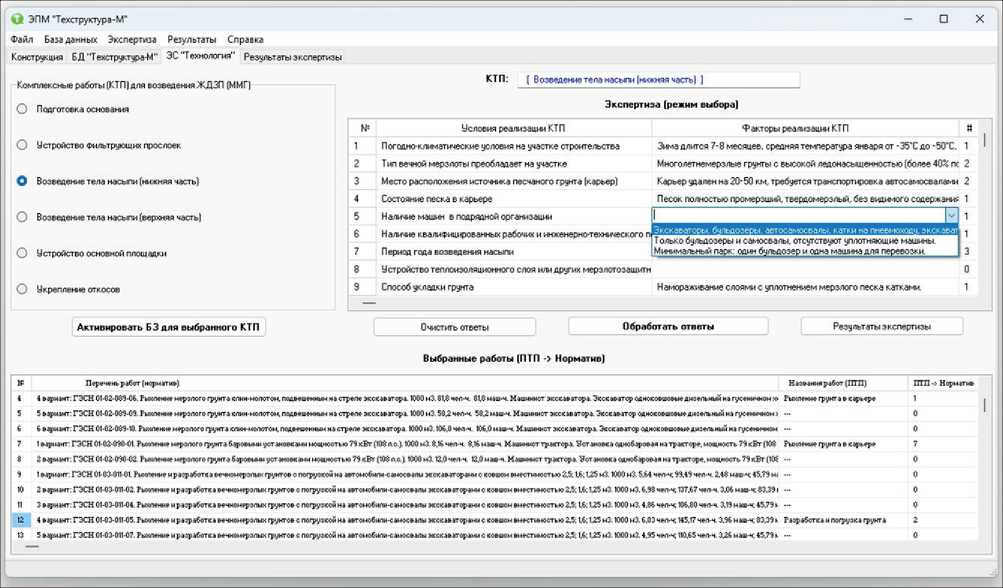
3) “ES Technology” – allows selecting factors based on CTP implementation conditions for constructing an RS structural element on PS, determining the logical sequence of STP and their corresponding works from normative sources (Fig. 11);
-
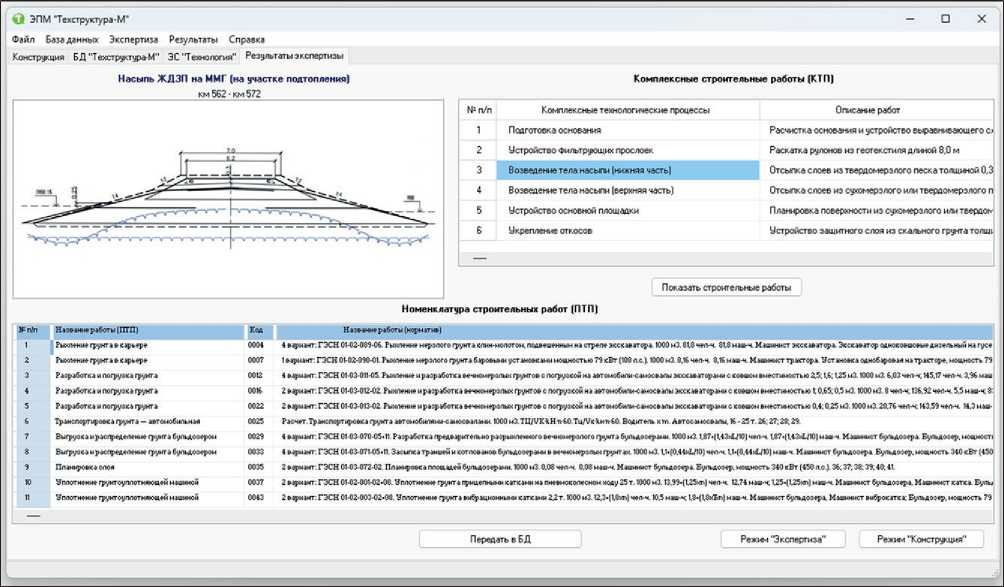
4) “Expertise Results” – presents the results of the expertise – the nomenclature of construction works (STP) for constructing RS on PS, which contains the following set of data (Fig. 12):
{ [Work code. Work name. Measurement unit. (Time standards). (Machine time standards). (Labor resources). (Technical means). (Identifiers of subsequent works)]>}. The fragments of the operation of the ESM “Techstructure-M” presented in Fig. s 9–12 demonstrate the step-by-step generation of the nomenclature of construction works, from the procedure of analyzing the constructional elements of the RS embankment to the formation of a list of works for the entire structure. At the first stage, a list of CTP is determined, linked to the list of constructional elements for the considered section of the RS. At the second stage, in accordance with the proposed implementation conditions and factors of the CTP (for constructing the considered structural element of the RS on PS), STP are identified. Simultaneously, Fig. 9. Operating mode of the ESM “Techstructure-M”: “Structure” SYSTEM SOLUTIONS FOR TECHNOLOGICAL PROBLEMS Fig. 10. Operating mode of the ESM “Techstructure-M”: “DB Techstructure-M” Fig. 11. Operating mode of the ESM “Techstructure-M”: “ES Technology” SYSTEM SOLUTIONS FOR TECHNOLOGICAL PROBLEMS Fig. 12. Operating mode of the ESM “Techstructure-M”: “Expertise Results” based on the rules, a normative description of the work is linked to the STP, taken from state unit-cost standards (GESN) collections, or a calculation formula is proposed to determine technological parameters. The results of generating the NCW, including the list of STP with their attributive characteristics, can be saved in the database, ensuring their availability for subsequent analytical processing. Table 2 shows a fragment of the list of works (STP) included in the comprehensive technological process “3. Construction of the lower part of the embankment body.” The list of works presented in Table 2 takes into account the linkage to specific resources of the construction (contracting) organization, so some tasks allow for multiple execution variants. It is clear that with a small number of variants, it is not difficult to select one that satisfies one or more requirements. However, as variability increases, the task of forming an optimal list of works arises. Essentially, this requires solving the problem of creating an optimal technological process that meets efficiency criteria (optimality criteria). Thus, there is a need to solve an optimization problem, which is complicated by the presence of multiple criteria and high dimensionality. Solving such a problem is the subject of further research and the application of tools, including those related to the field of artificial intelligence. CONCLUSION The results of the technological justification of design solutions for RS on PS form the foundation for implementing engineering-intelligent approaches in the design of technological processes. The obtained results enable the formation of a nomenclature of construction works, which becomes the basis for developing labor cost estimates, optimizing the organizational structure of the technological process, and creating work production projects. The following aspects of applying the research results are of particular importance: 1. Formalization of technological relationships – the obtained graph models of constructional elements and their interconnections allow for the automatic generation of STP lists, minimizing the human factor in the formation of OTD. 2. Multicriteria optimization – data on STP parameters (labor costs, timelines, resources) serve as input for optimization algorithms, including genetic and neural network methods. This ensures the selection of the optimal sequence of operations, considering criteria such as reducing construction time, lowering costs, or minimizing risks under PS conditions. 3. Integration into digital platforms – the nomenclature of construction works can be incorporated into automated construction management systems, accelerat- Table 2. Fragment of the list of works included in the comprehensive technological process “3. Construction of the lower part of the embankment body” No. Construction works (STP) Justification, Code Name of works according to normative sources Time standard, Crew composition Machines. men-h mach.-h 2.5.2 Compaction using a soil compaction machine GESN 01-02-003-02+08 Compaction of soil using 2.2 t vibratory rollers 12.3 10.5 1.8+(1.8×n) Bulldozer Operator, Vibratory Roller Operator Bulldozer, power 79 kW (108 hp); Self-propelled vibratory road roller, mass 2.2 t 3. Construction of the embankment (lower part) 3.1.1 Loosening soil in the quarry GESN 01-02-089-06 Loosening frozen soil using a chisel hammer suspended from the excavator arm 81.8 81.8 Excavator Operator Single-bucket diesel excavator on crawler tracks, bucket capacity 0.65 m³ 3.1.2 Loosening soil in the quarry GESN 01-02-090-01 Loosening frozen soil using bar-mounted units with a power of 79 kW (108 hp) 8.16 8.16 Tractor Operator Single-bar unit mounted on a tractor, power 79 kW (108 hp), slot width 54 cm 3.2.1 Excavation and loading of soil GESN 01-03-011-05 Loosening and excavation of permafrost soils with loading onto dump trucks using excavators with bucket capacities of 2.5, 1.6, and 1.25 m³ 6.03 145.17 3.96 83.39 28.91 Workers, Bulldozer Operator, Excavator Operator ×2 Bulldozer, power 79 kW (108 hp); Single-bucket diesel excavator on crawler tracks, bucket capacity 0.65 m³; Single-bucket diesel excavator on crawler tracks, bucket capacity 1.6 m³ 3.2.2 Excavation and loading of soil GESN 01-03-012-02 Loosening and excavation of permafrost soils with loading onto dump trucks using excavators with bucket capacities of 1, 0.65, and 0.5 m³ 8 136.92 5.5 83.39 48.03 Workers, Bulldozer Operator, Excavator Operator ×2 Bulldozer, power 79 kW (108 hp); Single-bucket diesel excavator on crawler tracks, bucket capacity 0.65 m³; Single-bucket diesel excavator on crawler tracks, bucket capacity 1.0 m³ 3.2.3 Excavation and loading of soil GESN 01-03-013-02 Loosening and excavation of permafrost soils with loading onto dump trucks using excavators with bucket capacities of 0.4 and 0.25 m³ 20.76 143.59 14.3 45.9 83.39 Workers, Bulldozer Operator, Excavator Operator ×2 Bulldozer, power 59 kW (80 hp); Single-bucket diesel excavator on crawler tracks, bucket capacity 0.4 m³; Single-bucket diesel excavator on crawler tracks, bucket capacity 0.65 m³ 3.3 Transportation of soil – by truck Calculation Transportation of soil by dump trucks TЦ/VК·kН·n·60 TЦ/VК·kН·n·60 Driver × m Dump trucks, 16–25 t 3.4.1 Unloading and spreading soil using a bulldozer GESN 01-03-070-05+11 Excavation of pre-loosened permafrost soil using bulldozers 1.87+(1.43×L/10) 1.87+(1.43×L/10) Bulldozer Operator Bulldozer, power 340 kW (450 hp) 3.4.2 Unloading and spreading soil using a bulldozer GESN 01-03-071-05+11 Backfilling of trenches and pits using bulldozers in permafrost soils 1.1+(0.44×L/10) 1.1+(0.44×L/10) Bulldozer Operator Bulldozer, power 340 kW (450 hp) 3.5 Layer planning GESN 01-03-072-02 Grading of areas using bulldozers 0.08 0.08 Bulldozer Operator Bulldozer, power 340 kW (450 hp) 3.6.1 Compaction using a soil compaction machine GESN 01-02-001-02+08 Compaction of soil using 25 t pneumatic-tired towed rollers 13.99+(1.25×g) 12.74 1.25+(1.25×g) Bulldozer Operator, Roller Operator Bulldozer, power 79 kW (108 hp); Towed road roller on pneumatic tires, mass 25 t; Crawler tractor, power 79 kW (108 hp) 3.6.2 Compaction using a soil compaction machine GESN 01-02-003-02+08 Compaction of soil using 2.2 t vibratory rollers 12.3+(1.8×g) 10.5 1.8+(1.8×g) Bulldozer Operator, Vibratory Roller Operator Bulldozer, power 79 kW (108 hp); Self-propelled vibratory road roller, mass 2.2 t 4. Construction of the embankment (upper part) 4.1.1 Loosening soil in the quarry GESN 01-02-089-06 Loosening frozen soil using a chisel hammer suspended from the excavator arm 81.8 81.8 Excavator Operator Single-bucket diesel excavator on crawler tracks, bucket capacity 0.65 m³ Note: in the table: L – length of the section (work zone); g – number of passes over the same track; m – number of dump trucks; ТЦ – cycle time of the dump truck operation; VК – bucket volume of the excavator; kН – coefficient of initial filling; n – number of buckets of soil loaded into the dump truck body SYSTEM SOLUTIONS FOR TECHNOLOGICAL PROBLEMS ing the development of schedules and monitoring work progress in complex climatic and geological conditions. The obtained results not only establish a basis for the intellectualization of technological design in railway con- struction under PS conditions but also open prospects for the digital transformation of the industry, ensuring compliance with modern standards of construction safety and economic efficiency.