«Тепловой байпас» или движения воздуха, вызывающие значительное увеличение тепловых потерь

Автор: Якшич Желько, Хармати Норберт
Журнал: Строительство уникальных зданий и сооружений @unistroy
Рубрика: Энергоэффективность и энергосбережение
Статья в выпуске: 11 (26), 2014 года.
Бесплатный доступ
Целевое сокращения выбросов СО2 на национальном уровне до 80% и необходимость создания«безуглеродных» зданий привлекли внимание специалистов в области проектирования и оснащениязданий. Появление «теплового байпаса» оказывает значительное влияние на совершенствование конструкции для развития жилищного строительства, что приводит к развитию новой системы обеспечения качества. Следует признать, что термин «тепловой байпас» в основном относится к неизвестной и часто нерегулируемой теплопередаче. В этой статье рассматриваются некоторые принципы устранения воздушных зазоров внутри и по обе стороны от изоляционного слоя, чтобы сохранить герметичную конструкцию, а также для защиты изоляционного слоя от ветрового движения воздуха.
Тепловая байпас, воздушные зазоры, конвективный цикл, энергоэффективность, герметизация, строительство
Короткий адрес: https://sciup.org/14322061
IDR: 14322061 | УДК: 69
Текст научной статьи «Тепловой байпас» или движения воздуха, вызывающие значительное увеличение тепловых потерь
The energy efficiency of the buildings means satisfying of all requests related to all physical components included in their thermal protection, as materials as well. In that case the standards that we pursue in the area of interesting of us, it seems obvious, lead us toward to the final optimal solution. However in most cases this is not the rule. Until nowadays many studies are confirmed leakage of the energy through the walls and panes.
The Governments legally binding objective of achieving an 80% reduction in national CO 2 emissions and the drive for zero carbon homes and buildings is focusing attention upon building design and procurement. The needs for systemic change is increasingly recognised as there is mounting evidence to suggest that buildings that are being designed to achieve thermal performance standards, including the Building Regulations, are in fact consuming in excess of 40% more energy than the predicted values. In some cases the increase in energy consumption can be up to 70% greater than that predicted. So why does this gap between calculated performance and reality exist? The principle reason for these failures in performance is not so much due to the materials that are being utilised but rather systematic failings in the regulatory calculation methods and the standards of design and workmanship. In developing the design for a residential development concerns relating to the subject of “thermal bypass” have had a significant influence upon the project and lead to the development of new quality assurance systems. The main goal is how to defeat thermal bypass [1-28].
-
1. Thermal bypass1.1 . What is thermal bypass
Thermal bypass is heat transfer that bypasses the conductive or conductive-radiative heat transfer between two regions [1]. Defined in this manner convective loops, which include both air infiltration and windwashing. In this context that it should be recognised that the term thermal bypass is being applied to largely unfamiliar, and often unregulated, heat transfer. Furthermore it is an acknowledgement that air movement can lead to a significant increase in the heat loss when compared to predicted values. This means that even when the architect, and builder, thinks that a design has addressed the performance requirement it is very likely that it has not.
In principal there are two forms of convective loop bypass that occur predominantly through natural convection (figure 1). “Closed loop” convection may be observed where the air mass remains largely unchanged but temperature differences exist at the boundaries causing re-circulatory air flow whereby the air moves in a loop. A good example of this could be an unventilated cavity wall. “Open loop” convection allows an air mass to be replaced by other air and therefore includes air gaps that permit air flow, and thus heat transfer, between two regions. This form of heat loss is the result of failures in airtightness and wind tightness.
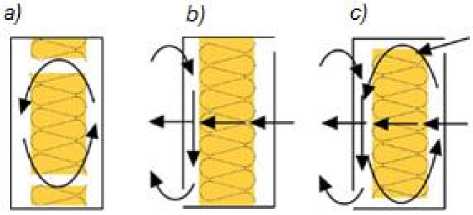
Figure 1. a) Closed loop b) Open loop c) Combined bypass loops
“Closed loop” convection can result in significant failures in thermal performance. In principle this is driven by stack effect. A range of studies have shown that even narrow air gaps between the (internal) air barrier and the insulation and small gaps in the joints between insulation have been shown to result in significant heat loss. The proportionate impact of the convection increases as the U-value is improved. An increase in heat loss of about 160% greater than the calculated U-value is not uncommon when air gaps exist behind the insulation.
In principle “Open loop” convection this is driven by the wind penetrating the thermal envelope. This form of heat loss can be addressed by airtightness and windtightness. Airtightness may be defined as “the property of preventing air from penetrating through the shell” and windtightness as “the property preventing air from penetrating into the shell so that the thermal insulation property of the insulation material is not reduced.” In reality it is often found that both Open and Closed loop bypass can occur at the same time.
Windwashing can affect the thermal performance insulation, short-circuit the performance of insulating sheathing, and cool down an air barrier system located towards the outside of the wall assembly (potentially below the dew point temperature). Poor windtightness has been shown to result in catastrophic failures in thermal performance; one study examining as-built defects reports that the heat loss was increase by up to 660% beyond the U-value. Admittedly this is an extreme example it would appear that an increase of 40% may be more common where adequate windtightness is not achieved. Areas that are at particular risk to wind washing are eaves, gables, ridge and corners.
-
1.2 How thermal bypass affects?
-
2. Designing to avoid thermal bypass
Airtightness is an umbrella term that is used to establish performance criteria that impacts upon thermal transmittance, dynamic thermal response, moisture tolerance, sound insulation, draft discomfort and energy consumption. Air flow through 300mm of insulation, with a velocity of 2.5m/s, would result in a 35% reduction in thermal performance. For this reason airtight construction is a prerequisite and all joints, cracks and services penetrations through the air barrier should be sealed accordingly.
The air flow through a 1 mm wide one meter long joint, transports approximately 360g water per day when there is a pressure difference of just 2 Pa, the stack effect occurring over two storeys. In the winter across the section of an insulated wall the temperature gradient falls towards the outside.
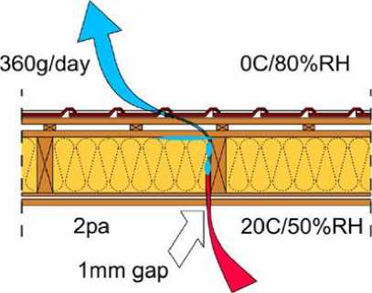
Figure 2. Moisture movement through stack effect
In the example given above, where there is poor airtightness and the temperature falls below the dew point, substantial condensation will occur which can lead to mould growth and the damage of timber. In contrast the quantity water vapour transported via diffusion is very small. Assuming suitable attention is given to vapour diffusion the greatest risk to moisture performance is poor airtightness.
The principle recommendations are to eliminate air gaps within and either side of the insulation layer, to preserve airtight construction, and to protect the insulation layer against wind induced air movement. A number of simple guidance notes for designing and constructing air and wind tight barriers emerge from this basis premise [3].
-
- Mark up the plans, sections and details so that they clearly delineate the air barrier, (say using a red line for airtightness and a blue line for windtightness).
-
- Ensure that the respective barrier remains unbroken. Play particular attention to continuity at structural openings and services penetrations. If you identify any gaps find a simple solution that allows the barrier be continuous.
-
- Keep it simple, keep it safe: avoid unnecessary kinks and bend (avoid complicated solutions that require skills in origami).
-
- Minimise the number of joints: when using/specifying membranes use wide rolls or continuous wet finishes.
-
- Seal all joints: use caulking or tape and mechanically clamp the joint between two solid plates (say between
a stud and plasterboard). To assist sealing fix membranes vertically from eaves to sole plate so that the side lap coincides with a stud (similarly ridge to eaves for the roof). This ensures that the joint can be filled with mastic and/or taped with a batten nailed over to give a long-term physical connection.
-
- Consider building movement and settlement. For wet barriers consider reinforcing the corners using membranes covered with expanded metal, and provide membranes at window junctions. Membranes should
overlap by 150mm and should not be pulled tight at the corners (leave a half round loop 5-10mm diameter at movement joints, windows, eaves, ridge etc).
-
- Do it once, do it right: determine the principle air barrier and ensure that this is tasted and, where necessary, repaired. Do not rely upon the secondary sealing of non-air barrier systems to achieve airtightness (this is costly, time consuming and very likely to result in poor longevity of the air barrier).
-
- Encapsulate the insulation between the wind and air barrier.
-
- Voids should be designed out: especially those that remain on the warm side of the insulation (you may need to consider the insulation installation methodology: e.g. for timber frame installation from the outside towards the air barrier). Insulation must completely fill the element but must not be compressed too much such that deformations occur. Insulation should be about 5 to 10mm thicker than required so that the closing board will lightly compress the insulation along the entire surface area.
-
- Avoid the formation of interlinking cavities by designing the building elements as discrete components, i.e. close cavities at wall to wall junctions (including corners), between walls and roofs and walls and floors.
-
2.1 Air and wind barrier concepts and strategies
-
2.1.1 The thermo-shield difference
-
2.1.2 Regulatory matters: current status
(These guidance notes have been prepared by Mark Siddall)
A rang of wind and air barrier options exist. Table 2 has been developed with reference to Elmroth [4], Timusk [5] and Proskiw [6] and modified from Carlsson [7].
Ventilated cavities are often utilised to prevent rainwater from entering the building. After studying hydrothermal performance Hens [8] has cast doubt on the need for ventilation within masonry walls. The details that tend to be most susceptible to wind washing are vertical corners and the tops of walls (eaves, verge and ridge), horizontal and pitched assemblies (such as raised insulated floors that separate an unheated garage from a living space above and cantilevered or suspended living spaces and compact/cathedral roofs). The key to controlling this phenomenon is to increase the resistance to external airflow circulation; as noted above this may be achieved by air and wind tight construction and the compartmentalisation of the cavity behind a rainscreen (this may be achieved with vertical furring strip).
A quick survey of European standards suggests that limited attention has been given to the mechanisms of convective thermal bypass and it is subsequent control. Airtightness appears to be the topic that is highest on the agenda. In the context of thermal bypass similar regulatory failures exist in Austria [9], England and Wales [10] and even advanced voluntary standard such as the PassivHaus standard do not explicitly consider the issue of thermal bypass at party walls [11] or windtightness (table 1) [3].
Table 1. Air and wind barrier concepts and strategies
|
Method |
Detail |
Advantages |
Disadvantages |
|
Internal airtight cladding e.g. plaster, parge or, plasterboard |
|
|
|
|
Drawn under sealing layer e.g. paper or foil |
projects, and future rewiring etc (during the operational life) is possible without the sealing strip being damaged.
|
insulation and carpentry and furnishing, e.g. on moisture conditions in the sealing strip, in particular, are unknown
|
|
Method |
Detail |
Advantages |
Disadvantages |
|
|
External air sealing and wind protection |
to programme and before substantial completion.
or strapping to accommodate services and can be repaired externally before being covered
life) is possible without the sealing strip being damaged
|
|
||
|
WARNING FOR THIS DETAIL A co m bined external wind/air barrier could permit windwashing. This would occur as a result of the wind/air barrier acting like a diaphragm whereby warm internal air is drawn into the depth of the wall element assisting heat loss and thus increasing the U-value. This action could also draw moisture into the structure. There is also the risk that the convective currents that are present within a building (induced by opening external doors, MVHR etc.) could assist the vapour transport through any unsealed joints in the vapour barrier. This action could also draw moisture into the structure. |
||||
|
Combination of internal and external air sealing |
• Double safety for air sealing. |
|
||
|
Homogenous constructions e.g. cellular concrete |
^^^^^^^ |
|
•Limited choice of materials.
|
|
Conclusion
For buildings to perform as expected the ability for designers and non-designers (clerk of the works, constructors trades and) to recognise and avoid thermal bypass mechanisms is critical. If thermal bypass is to be addressed, and carbon reduction objectives are to be met, industry wide training needs provided at a national level. This training should be supported by revisions to building regulations in such a way that it is a requirement that all building elements should be adequately airtight and windtight in all directions so that all potential closed loops are protected from temperature gradients at boundaries (which can induce convection) and that any open loops are designed out. Until then building failures will continue and a cost to both clients, government and the environment.
Acknowledgements
The work reported in this paper has been financially supported in the scope of the University of Novi Sad, Faculty of Technical Sciences, Project: “Theoretical, experimental and applied research in the field of civil engineering”.
Список литературы «Тепловой байпас» или движения воздуха, вызывающие значительное увеличение тепловых потерь
- Jakšić, Ž., Harmati, N. Resolving the issue of disrupting characteristic thermal bridges in building structures, Journal for research in the field of materials and structures, SMSTS (DIMK), 2013, Belgrade, pp. 59-80
- Bankvall, C.G. Forced Convection: Practical Thermal Conductivity in an insulated structure under the influence of workmanship and wind, ASTM STP 660, 409-425 (1978).
- Siddall, M. The impact of Thermal bypass, Green Building Magazine, Vol. 19, No 1, 2009, pp. 237-245.
- Elmroth, T. Air infiltration control in housing -A guide to international practice, AVIC/Swedish Council for Building Research, Stockholm, Sweden (1983), pp.178-186.
- Timusk, J, Seskus, A.L., Ary, N. The control of wind cooling of wood frame building enclosures˝, Journal of Thermal Insulation 15, 8-19, (1991), pp. 564-572.
- Proskiw, G., Eng, P. Varriations in Airtightness of Houses Constructed with Polythene and ADA Air Barrier Systems Over a Three-Year Period, Journal of Building Physics, vol. 20, (1997), pp. 278-296.
- Carlsson, B., Elmroth, A., Engvall, P. Airtightness and Thermal Insulation: Building Design Solutions, Swedish Council for Building Research, (1980), pp. 567-576.
- Hens, H., Janssens, W., Depraetere, J., Carmeliet, J., Lecompte, J.,: ˝Brick Cavity Walls: A Performance Analysis Based upon Measurements and Simulations˝, Journal of Building Physics, vol. 31, (2007), pp. 95 -123.
- Deseyve, C., Bednar, T. Increased Thermal Losses caused by Ventilation through Compact Pitched Roof Constructions -In Situ Measurements, Seventh Nordic Building Physic Simposium (2005), pp. 786-794.
- Wingfield, J., Bell, M., Bell, J.M., Miles-Shenton, D., South, T. & Lowe, R.J. Evaluating the Impact of an Enhanced Energy Performance Standard on Load-Bearing Masonry Domestic Construction, Interim Report Number 7, Centre for the Built Environment, Leeds Metropolitan University, (2007), pp. 198-205.
- Warm, P., Clarke, C. Projecting energy use and CO2 emissions from low energy buildings: A comparison of the PassivHaus Planning˝, Package (PHPP) and SAP, AECB, (2008).
- Google figures URL: https://www.google.rs/search?q=thermal+bypass&tbm=isch&tbo=u&source=univ&sa=X&ei=lkScUuTpOcTVtAai8 4BA&ved=0CDMQsAQ&biw=1680&bih=799 (dare of reference: 10.10.2014)
- Greenspec URL: http://www.greenspec.co.uk/thermal-bypass.php (dare of reference: 10.10.2014)
- Влияние воздухоизоляционного состава на теплотехнические характеристики ограждающих конструкций/Платонова М.А., Ватин Н.И., Немова Д.В., Матошкина С.А., Иотти Д., Того И.//Строительство уникальных зданий и сооружений. 2014. №4 (19). С. 83-95.
- Vatin, N., Nemova, D., Tarasova, D., Staritcyna A. Increase of energy efficiency for educational institution building. (2014) Advanced Materials Research, Vols. 953-954, pp. 854-870.
- Murgul, V. Features of energy efficient upgrade of historic buildings (illustrated with the example of Saint-Petersburg). (2014) Journal of Applied Engineering Science, Vol. 12 (1), pp 1-10
- Nemova, D., Murgul, V., Golik, A., Chizhov, E., Pukhkal, V., Vatin N. Reconstruction of administrative buildings of the 70s: the possibility of energy modernization. (2014) Journal of Applied Engineering Science, Vol. 12 (1), pp. 37-44
- Pukhkal, V., Murgul, V., Vatin, N. Central ventilation system with heat recovery as one of the measures to upgrade energy efficiency of historic buildings. (2014) Applied Mechanics and Materials. (2014) Vols. 633-634 pp 1077-1081
- Murgul, V., Vuksanovic, D., Vatin, N., Pukhkal V: The use of decentralized ventilation systems with heat recovery in the historical buildings of St. Petersburg. (2014) Applied Mechanics and Materials. Vols. 635-637 (2014) pp 370-376
- Vatin, N., Nemova, D., Kazimirova, A., Gureev, K. Increase of energy efficiency of the building of kindergarten. (2014) Advanced Materials Research, Vols. 953-954, pp. 1537-1544.
- Vatin N. I., Gorshkov A. S., Nemova D. V., Staritcyna A. A., Tarasova D. S. The energy-efficient heat insulation thickness for systems of hinged ventilated facades. Advanced Materials Research, Vols. 941-944, (2014), pp. 905-920.
- Murgul, V., Vuksanovic, D., Pukhkal, V. Vatin N. Development of the ventilation system of historic buildings in St. Petersburg. (2014) Applied Mechanics and Materials. Vols. 633-634 pp. 977-981
- Zadvinskaya T.O., Gorshkov A.S. Comprehensive method of energy efficiency of residential house. Advanced Materials Research. (2014). Vol. 953-954. pp. 1570-1577.
- Murgul, V., Vuksanovic, D., Vatin, N., Pukhkal, V. Decentralized ventilation systems with exhaust air heat recovery in the case of residential buildings. (2014). Applied Mechanics and Materials Vol. 680. pp 524-528
- Pukhkal, V., Stanojevic, D., Murgul, V., Vatin, N. Exhibition pavilions car showrooms based on translucent structures: providing microclimatic comfort for clients. (2014) Applied Mechanics and Materials. Vol. 680 pp 467-473
- Vuksanovic, D., Murgul, V., Vatin, N., Pukhkal, V. Optimization of microclimate in residential buildings. (2014) Applied Mechanics and Materials Vol. 680 pp 459-466
- Мургул В. Возможности использования солнечной энергии для энергоснабжения жилых зданий исторической застройки Санкт-Петербурга и улучшения качества городской среды//Архитектон: известия вузов. 2012. 4 (40). С. 54-62.
- Ватин Н. И., Горшков А. С., Немова Д. В. Энергоэффективность ограждающих конструкций при капитальном ремонте//Строительство уникальных зданий и сооружений. 2013. №3 (8). С. 1-11.
