The accuracy of the contact method of measuring the current area of the crystals grown by the Czochralski method

Author: Sahansky Sergey P.
Journal: Журнал Сибирского федерального университета. Серия: Техника и технологии @technologies-sfu
Article in issue: 8 т.9, 2016.
Free access
For crystals grown from a liquid melt using the Czochralski method, under the control of the current area of the crystal on the basis of the contact measurement method, defines the requirements for ensuring the accuracy of measuring the value of 1 %.
Cultivation, crystals, contact measurement method
Short address: https://sciup.org/146115161
IDR: 146115161 | UDC: 004.7 | DOI: 10.17516/1999-494X-2016-9-8-1279-1290
Точность контактного метода измерения текущей площади кристаллов, выращиваемых способом Чохральского
Для кристаллов, выращиваемых из жидкого расплава по способу Чохральского, при контроле текущей площади кристалла на основе контактного метода измерения определены требования для обеспечения точности измерения величиной 1 %.
Text of the scientific article The accuracy of the contact method of measuring the current area of the crystals grown by the Czochralski method
Microprocessor control system in growing germanium crystals, developed on the basis of patents [1, 2], have been implemented in a semiconductor production growing the germanium crystals (Fig. 1).
Job management systems based on a contact method of measurement of the current space grown crystals is as follows: under control of the camera control system is made growing crystal diameter d , with velocities V з cultivation and rotation W з crystal with molten metal in a crucible with an inner diameter D is rotated with an angular velocity in descending W т melt in the crucible.
The signal from the contact sensor is supplied through the smoothing filter C1, R1, R2 and coordination unit to a computer to make a decision about how to manage the rise of the crucible up, which is carried out by the control unit stepper motor. In addition to the crucible lifting speed up the V in the system is the formation of information on the movement of the crucible X (in increments т итц of xт) and information about how to move Xизц crystal (in increments of xз). Management of computer speed Vз growing crystal, crystal Wз rotation, crucible rotation Wт, through respective drives. The melt temperature is controlled based on the formation temperature Тз jobs from a computer on the temperature controller, with feedback on the sensor side of the surface temperature of the heater.
Control of crystal growing speed V (x), the lateral surface of the heater temperature T(x), the зз crystal rotation speed Wз(x), of the crucible Wт(x) is generated based on the expressions (1) – (4):
V ( X ) = V ( X ) + Z - K , • y,
W3 (x) = Wm (x),(3)
Wm (x) = Wтп (x),(4)
where K V – proportional control factor for speed; A T – integral factor for temperature regulation; V зп ( x ), W зп( x ), W тп( x ), T зп( x ), – software job law changes of process parameters; V з( x ), W з( x ), W т(x), T з( x ) – the overall control process parameters; Z – a sign of seizure control in diameter at the cylindrical portion of the crystal; x – movement along the axis of the crystal; y – a control signal from the deviation of the current area of the crystal grown on the set.
The stabilization process takes place in the crystal diameter control system according to the expressions (1) – (2), when the capture control characteristic diameter ( Z = 1) on the cylindrical portion of the crystal based on the control signal y .
Policy objectives of technological parameters of the germanium crystal growing V зп ( x ), W зп ( x ), T зп( x ) in the process of microprocessor-based systems have been based on the task of personnel system control parameters, where each frame is recorded speed, direction of change of the parameter and the time frame. If the set geometry of the growing crystal and its axial gradient in the solid portion, it is possible to simulate the pre-form and the speed of growth temperature on all parts of the crystal growth by the model developed by the author [3].
The design of the automatic control system by pulling the single crystals of germanium is shown in Fig. 2, Fig. 3 is a view of the floating of the graphite graphite screen melt level sensor, and Fig. 4 shows a grown single crystal ingot of germanium with a diameter of 104 mm.
The basis for the contact monitoring and control method of growing crystals [4] is the management of the current area (or diameter if circular shape) of the growing crystal, the y control signal, calculated as a function of the deviation of the current chip area from the given chin area, with movements crystal X зц and crucible X тц for assessment period T ц control signal y .
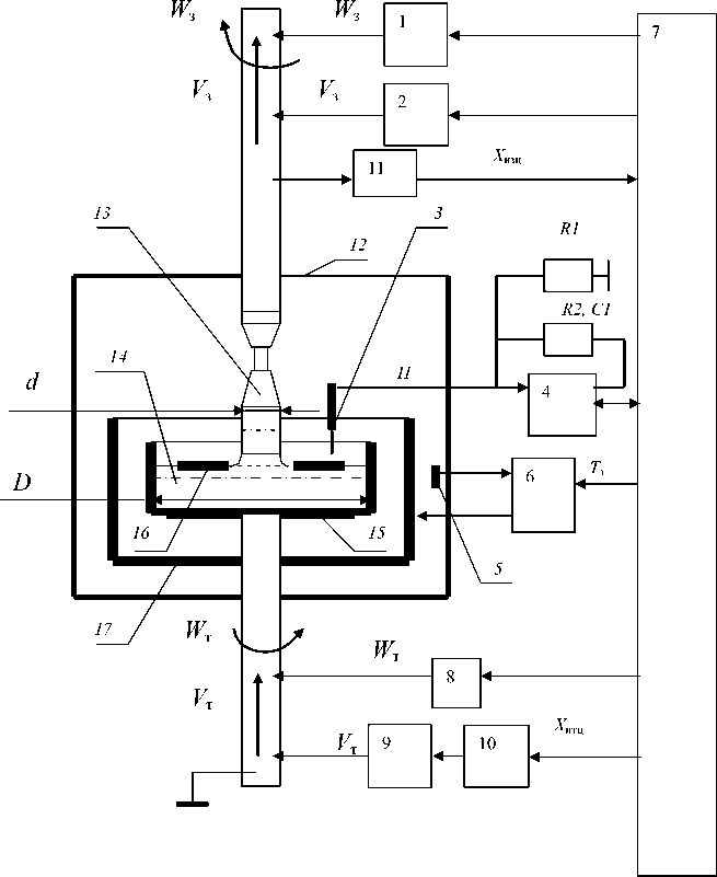
Fig. 1. The control system based on contact measurement method: 1 – priming rotary drive; 2 – priming the actuator movement; 3 – contact sensor; 4 – unit agreement with the computer; 5 – a temperature sensor; 6 – temperature controller; 7 – PC; 8 – the crucible rotation drive; 9 – stepper motor; 10 – a control unit stepper motor; 11 – the gauge of moving seed; 12 – camera; 13 – bar; 14 – molten metal; 15 – the crucible; 16 – the screen; 17 – heater
The accuracy of determining the control signal y and the absence of significant value in the calculated interference depends on the shape of the growing crystal its cylindrical portion.
The rate of decrease of the melt in the crucible V р, as well as the accelerated crucible lifting speed up V тм after the opening of the contact sensor and the slow speed of the crucible after lifting circuit contact sensor V тм / M determined by the expressions (5) – (9), in which the rate of increase in rates introduced ( C = 4) and the crucible lifting speed reduction ( M = 4) that has been used in growing the crystal, and cylindrical portion allows a periodic opening and closing of the contact sensor in range of the melt level of about 1-2 µm. When growing the forward and reverse cone of the crystal to control the speed of the crucible moving upwards, the condition applies to a complete stop of the crucible lifting moments melt level in the closed condition of the sensor ( M = ∞).
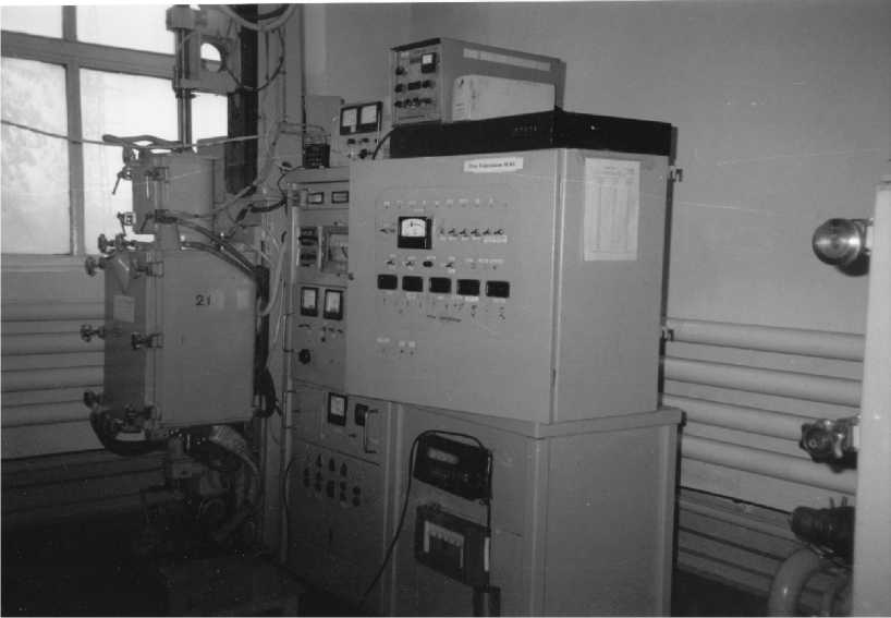
Fig. 2. Microprocessor control system pulling single crystals of germanium
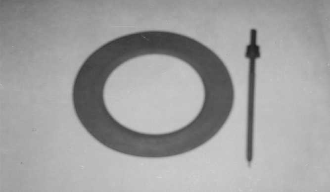
Fig. 3. The floating screen and graphite melt level sensor

Fig. 4. Ingot germanium diameter 104 mm
Р т
V р = V з • Рж
•
d
D
,
Vтм = V P •
d max d
= V • Р
3 Р ж
•
max
D
,
d = d, • max 1
1-Uc ’
v
тм _ у . Mр
d min 1 2 d _
Pm з" Р ж"
d min, 1 D
,
d„ = d„ • min max
M
where V р – velocity of decrease of melt in a crucible; V з – velocity of crystal growth; d – current diameter of the crystal; D – inner diameter of the crucible; ρ – beats. the density of the solid material;
т
ρ ж – beats. density of the liquid material; d 1 – nominal diameter of the crystal grown on the cylindrical portion; d max – maximum diameter of the growing crystal, which is performed in compliance with the basic condition in which the sensor and the screen after the opening of closeness; d min – the minimum permissible value of the crystal diameter at which the screen is observed lag condition of the sensor after it has closed.
For the method of measuring the contact control signal y , the amount of movement of the crucible
, and the seed Xзц, Xтц, Tц during the evaluation can be represented as expressions (10) – (13):
y X итц
K
У - X изц
A * B A
K y = B •
x • p т р ж
D 1 2
x з • Рт
d 1
X изц y = A
Г d 1
A
•
(L d i J
- 1
,
X зц X изц ' x 3 ,
Y = Y • r тц итц x т ,
where А and В – scaling factors; K у – setting of a given diameter (area) of the growing crystal; X изц – moving from discrete samples seed x з ; X итц – moving the crucible in increments starting x т ; x з – sampled move seed; x т – sampled moving crucible.
Expression (12) shows the direct connection of the control signal y from the current deviation from the given chip area. During evaluation cycle T ц control signal y calculated by the expression in a control system (10), and by recording in diameter K у setpoint control system, on the cylindrical part of the growing crystal is set cultivation area.
The drive to control the rise of the crucible lifting speed up use open stepper drive with a stepper motor, which provides a process of the crucible lifting speed multiple changes in a signal from the contact level sensor.
The expressions for the pulse movement from seed X изц, the crucible X итц and time T ц estimate of the control signal y can be represented in the form of (15-16):
X изц
K
B,
Xизц " x з = X ®. = Xитц " K y " x 3 V V з B " V .
where T ц – the evaluation period of the control signal (the time of processing a predetermined number of X итц or X изц pulses).
Time total movement t in the circuit contact sensor with slow speed and time of the total movement at an accelerated pace crucible movement after opening sensor t д, as well as the number of cycles K ц for opening and closing sensor for the assessment period signal T ц management can be represented as expression ( 17) – (18):
t д ( d ) = t •
T ц
K ц =1^'
where t - movement while the crucible in slow motion after Vтм/M sensor circuit for the evaluation period segal management; tд – the movement of the crucible at an accelerated pace after the opening Vтм sensor for the assessment period segal management; K – the number of closing cycles and the opening ц of the sensor during the time Tц.
Automatic control system provides a range of diameter changes in accordance with the expressions (19-21):
d pp = d . ■ г-Ц- . (20)
V C • a
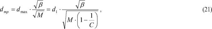
where d – current diameter of the crystal; d рр – maximum diameter; d mp – the minimum diameter; α – maximum diameter ratio; β – the minimum diameter ratio.
Evaluation time slow motion of the crucible, for extreme minimum diameter range values t ( d mp ), may be given as the expression (22):
t ( dmp ) = T =
L P ^ T X_. • E
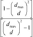
where E =
M -[ 1 - — I
I C ) evaluation.
; L p – the maximum reduction in the level of the melt; T ц – a period of the signal
The number of opening and closing cycles K ц sensor can be represented as the expression (23):
K ц
X • E тц
L p ^l1
^^^^^^e
^^^^^^s
C
d 1 1 2 d
• M
d 1 1 2 d
^^^^^^e
^^^^^^s

+ | C -1 -

In the considered system control germanium stretching applied timing control diagram (Fig. 5) for the cultivation of the cylindrical portion of the crystal, which consists in the fact that in the control system at the time of the closure of the contact of the sensor is necessary to sustain a program pause τ closed and the subsequent pause τ open level sensor status. In moments of silence value τ state of touch sensor control system is not analyzed and control the rise of the crucible takes place with slow and fast speed of recovery in the crucible moments «conditionally» closed and «conditionally» open level sensor states. After holding two pauses going analysis of the conditions of the melt level sensor circuit and drive control move up the crucible.
This control increases the immunity of the method of calculating the current area on the cylindrical part of the crystal grown by the lack of response of the system to contact the sensor response in two moments of silence.
The value of the melt level opening on the cylindrical part of the growing crystal L p programmed within 2 µm, by selecting the pause time τ by the expression (22). Given the magnitude of the opening level of the melt 2 µm, requires precise manufacturing graphite mold screen (within 10 µm in thickness), and providing multiple computing control signal ( K ц cycles when the contact sensor circuits in the range of 8-10, during the measurement cycle), and the simultaneous preservation of the conditions of the constant rotation of the graphite of the screen during the entire process. graphite screen rotation condition is provided by light precipitated graphite needles at the end of the sensor (Fig. 3) having a fixed bottom position.
Since the expression of the control system (11) is written in setting area of the crystal growth K у , from the obvious relations error tasks dimetra growing crystal and the error deviation of the cylindrical shape of the graphite crucible will be defined by the expression (24):
df=d1⋅DDf , (24)
where d f - is the deviation on the instructions of the crystal diameter in “mm”; D f deviation on the instructions of the crucible diameter in “mm”.
Graph expression (24) shown in Fig. 6, from which it follows that when the inner diameter of the crucible D = 300 mm, and the cultivation thereof dimetra d 1 crystals in the range of 60 to 140 mm, for lack of control error within 1 %, the internal diameter of the graphite crucible to be produced to within 100 µm.
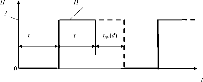
Fig. 5. The timing diagram working level sensor: H - the work of the contact level sensor (sensor Р - open)
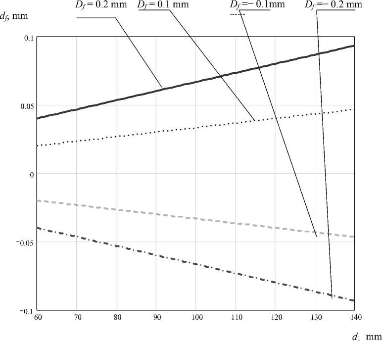
Fig. 6. Dependence of diameter d f at setting errors: D = 300 mm; D f = 0.2 mm; D f = 0.1 mm; D f = – 0.1 mm; D f = – 0.2 mm
When the coefficient A = 1, starting from the expressions (10) – (14), y control signal, the amount of movement of the crucible and the seed X зц, X тц, T ц during the evaluation can be represented as expressions:
y =
x з
X = V -T зц з ц
(V • t i
+ Aз • sml з + фз I,
I H3 J
X =V -T тц з ц
•
d1_ 1
D
+ Ат • sin
-19
D
V- J
•
IT + ф т т J
,
where A т – the amplitude of the interference on the movement of the crucible in the «µm “; A з – the amplitude of the interference on the movement of seed in the «µm “; V – crystal growth rate in the «mm/s»; Н т – step screw pair for moving the crucible in «mm»; Н з – step screw pair for moving the seed in «mm»; φ т – angle noise on the bias in the crucible in the «rad»; φ з – angle interference by seed displacement in the «rad»; t – time of the drawing process in a “s”.
The sinusoidal terms in expressions (30-31) account for errors in the trapezoidal screw pairs with a pitch periodicity screws for motion control systems seed rod and the crucible, which in turn creates a system without feedback on the movement of the main obstacle to the control signal f, which is based on the expressions (29-31) will be:
f = ^ ж • Р т
D
•
d i _
A т x з
• Sin
X" , -12
D v- J
V3 • t
• "Hr+фт т у
^^^^^^B
A з x з
- V3 • t
• sin -з— + ф3
V H 3
\
The time dependence of the error f shown in Fig. 7, it is consistent with the schedule of the basic error of measurement obtained at the industrial unit in Fig. 8. Error f corresponds manufacturing inaccuracies within the helical gear pitch screw pairs trapezoidal shape of Fig. 7 that the error f has a complex periodic view associated with periods of rotation of the screw pairs.
Since in the real process of growing phase error signal φ т and φ з is random, then take into account and to compensate for this error, based on the inspection and testing of the software installation drawing was impossible.
Reducing errors f possible through the use of precision ball screws or installation as a reference movement in the crystal growth setup by moving the coordinates of the seed and the crucible fotoschityvayuschih optic lines, with the discrete samples of 0.1 µm, which is the most viable option. In practice (without fotoschityvayuschih lines) when finalizing the drawing settings “Redmet-8” (Fig. 2) had to use a complex algorithm processing control signal that could not completely eliminate interference with the final shape of the growing crystal.
If applied to the measurement system, the coordinates move the seed and the crucible, as sensors for displacement feedback fotoschityvayuschie line, with discrete samples x т and x з equal to 0.1 µm, and ensure manufacturing precision forms the crucible of internal diameter D of at least 100 µm, and a thickness floating graphite shield is in the range of 10 µm, then taking the measurement cycle moving seed X зц the value of 0.5 mm, it is possible in the words of [12] to evaluate the accuracy of the control signal, which is shown in Fig. 9. Analysis of the expression shows that under the above conditions, the – 1287 –
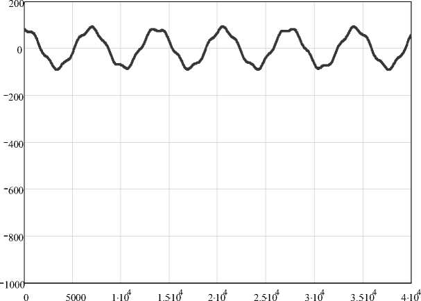
Fig. 7. Time-dependent control with error f : x т = 0.0266 µm; x з = 0.0216 µm; A т = 0.2 µm; A з = 0.2 µm; d 1 = 100 mm; D = 300 mm; Н т = 2 mm; Н з = 4 mm; φ т = π/2 rad; φ з = π/8 rad; V з = 0.0166 mm/ s; D = 300 mm; Н т = 2 mm; Н з = 4 mm; φ т = π/2 rad; φ з = π/8 rad; V з = 0.0166 mm/s
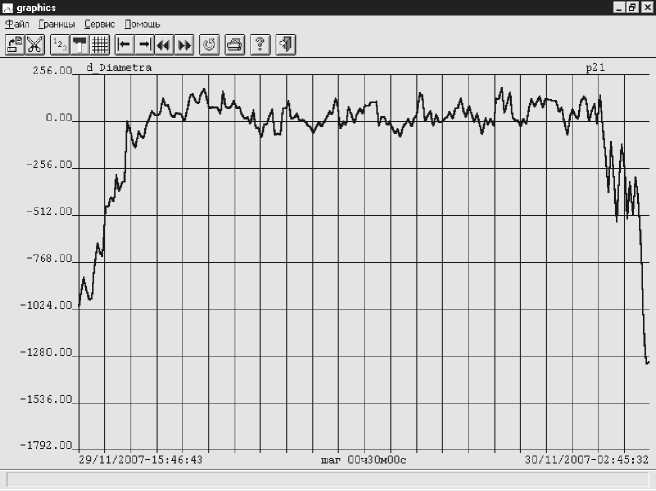
Fig. 8. Diagram of the control signal (d diameter)
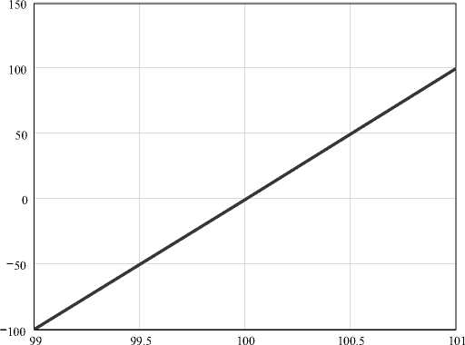
Fig. 9. The dependence of the control signal y from the current diameter of the deviation d from the set at d 1 : d 1 = 100 mm; x з = 0.1 µm; X зц = 0.5 mm
d , mm
attainable accuracy of calculation of the control signal y is a value of no worse than 1 % from a given area of crystal growth.
Findings
For crystals grown from a liquid melt using the Czochralski method, under the control of the current area of the crystal on the basis of the current method of measuring the contact area of the crystal, the basic requirements to ensure the accuracy of measurement of the current area of the crystal.
The system of control over the coordinates movement of the crystal and the crucible should be used fotoschityvayuschie optical line with a readability 0.1 µm, can build the inner diameter of the crucible with an accuracy of 100 µm and take the form of graphite floating screen in height with an accuracy of 10 µm, which will provide in the measurement accuracy of the current control system Square crystal size of 1 %.
References The accuracy of the contact method of measuring the current area of the crystals grown by the Czochralski method
- Пат. 2128250 Российская Федерация, МПКС30 В15⁄20, 15/22, 15/26. Способуправления процессом выращивания монокристаллов германия из расплава и устройство для его осуществления/С. П. Саханский, О. И. Подкопаев, В. Ф. Петрик -заявлено 16.01.97, опубл. 27.03.99, Бюл. № 9.
- Пат. 2184803 Российская Федерация, МПК С30 В15⁄20, 15/22, 15/12 29/08. Способ управления процессом выращивания монокристаллов германия из расплава и устройство для его осуществления/С. П. Саханский, О. И. Подкопаев, В. Ф. Петрик, В. Д. Лаптенок -Заявл. 12.11.99, опубл. 10.07.02, Бюл. № 19.
- Sahansky S. P. Control of the shape of semiconductor crystals when grown using the Czochralski method, J/Sib. Fed. Univ. Eng. Technol.,2014, 7(1), 20-31.
- Sahansky S. P. Measurement Square crystals grown from a liquid melt using the Czochralski method, based on the contact of the melt level sensor control circuit conditions, J/Sib. Fed. Univ. Eng. Technol.,2015, 7(8), 835-850.
