The calculation of technological effort for impact perforation and parts and products marking

Author: O.S. Polishchuk
Journal: Вестник Алматинского технологического университета @vestnik-atu
Section: Техника и технологии
Article in issue: 4 (121), 2018.
Free access
The article is devoted to the calculation of technological effort for impact perforation and parts and products marking in mechanical engineering and light industry, the development of devise with two-coordinate movement system. The analytical expressions that bind together the technological effort, properties of the material, instrument parameters and the implementation speed of the operation are obtained during this research. The results of the study can be used to design the device or calculate the technological effort, necessary for the implementation of mentioned operations.
Device with two-coordinate movement system, stepper motor, linear electric motor (lem), perforation, marking, technological effort
Short address: https://sciup.org/140243622
IDR: 140243622 | UDC: 621.795.8;
Определение технологического усилия для ударной перфорации и маркировки деталей и изделий
Статья посвящена определению технологического усилия для ударной перфорации и маркировки деталей и изделий в машиностроении и легкой промышленности, разработке конструкции устройства с двухкоординатной системой, использующей ударный эффект. В работе получены аналитические выражения, связывающие технологическое усилие, свойства материала, параметры инструмента и скорость выполнения операции. Результаты исследования могут быть использованы при проектировании устройства, а также при расчете технологического усилия, необходимого для выполнения указанных операций.
Text of the scientific article The calculation of technological effort for impact perforation and parts and products marking
Mechanical smite with percussion instruments with different types of drives is among the most promising ways to carry out technological operations. It provides a high concentration of load on the local area of the material and its energy of destruction is inferior to only the explosion.
The operation of parts punching of the top of different shoes with variable matrices is carried out in order to decorate it and increase air permeability. It is essentially similar to the operation of details cutting. Perforation can be regarded as holes punching of small diameters, the distance between which may be dimensional to the diameter [1].
The most commonly used technology for impact marking in the industry is impact-point marking. Impact-point industrial technology (micro percussion marking, needle marking, impact metal engraving, coring, stripping) is the application of individual points (spherical deepening) with the help of a high-strength needle made of solid metal alloys, using ceramics, on different types of materials under orders from the electronic controller [2].
On the basis of the analysis, it can be concluded that the use of the shock method for marking and branding of parts and products in mechanical engineering and light industry and the use of linear tools for working tools (cutters, punches, and needles) are promising in use.
When performing these operations, it is especially important to consider the following factors: the speed of processing object movement, the speed mode of the cutting or marking mechanical tool, the thickness of the cutting or immersion in the material with the ability to change the direction of movement of the working tool, the versatility of both the working tool and the entire mechatronic installation in general when working with different materials.
Reducing energy costs when performing technological operations of perforating and marking of parts and products by using new types of drives, as well as by selecting the best technological regimes, is a topical task and of interest to many industries.
Objects and methods of research
To improve the quality technological operation and reduce the power consumption of the equipment it is needed to achieve conformity between the forces that develop the press equipment and the technological effort. Such coordination will increase the lifetime of the puncher, press equipment, it will also improve its reliability and reduce energy consumption.
To calculate the impact energy of a linear electric motor of a two-coordinate system intended for performing parts and products perforation, marking and branding from different materials with different properties, it is necessary to know the amount of technological effort F and operation A .
Thus, it is important to evolve more accurate methods of calculation of technological effort and get аnalytical expressions that bind together the technological effort, properties of the material, instrument parameters and the implementation speed of the operation.
Results and their discussions
The work on the development of technical documentation and the production of an experimental installation that performs the operations with the consideration modern methods of controlled destruction of the processing objects structure with given coordinates and the established configuration according to the technological the process is carried out at Department of Machines and Apparatus, Electromechanical and Power Systems (MAEPS) of the Khmelnytskyi National University (Ukraine). The management of an experimental installation is carried out using an electronic calculating machine (ECM). Computer transmits necessary information to move the basic mechanisms within coordinates X and Y, and the stepper motors usage allows to position the working body or processing object with high accuracy within 0,01 - 0,05mm.
Mechatronic installation consists of two main units. A carriage with two-axis movement on the basis of running screws is used as a mechanism for mechanical portal movement with a working tool. The second basic element is the automation complex for stepping motors controlling with computer numerical control. This design allows us to extend the scope of the experimental installation for performing other technological operations, such as laser cutting.
First of all, in order to make up device with two-coordinate movement system for impact perforation and marking of parts and products, it was necessary to develop its structural scheme. The developed structural scheme is shown on the fig. 1.
The device includes: a system of parts moving, consisting of two mechanisms of movement along the coordinates X and Y; two stepping motors; stepper motor driver (CD); power supply for CD drivers; linear electric motor with shock mechanism; LEM power supply and control; electronic calculating machine (ECM) [3].
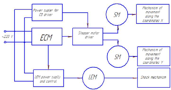
Figurе 1 - Structural scheme device with two-coordinate movement system for impact perforation and marking of parts and products
The general look of a machine with two-coordinate movement system for the details perforation of the top of the shoes is shown on the fig. 2. The main elements are: a device for performing a two-coordinate movement of the shoe parts with a fixed linear electric motor de-signned for perforating the shoe parts; stepper motor control system; stepper motor driver power supply unit and linear electric motor control.
The principle of the developed machine is as follows. The top detail of the shoe is placed on the desktop. Before that, with the help of the developed software, a necessary drawing is created for the perforation operation. The machine is put into operation and according to the developed program, with the help of a punch of a linear electric motor, the perforation of the part takes place.
You can perform the operation of marking parts or products by replacing the punch with a needle and creating a corresponding.
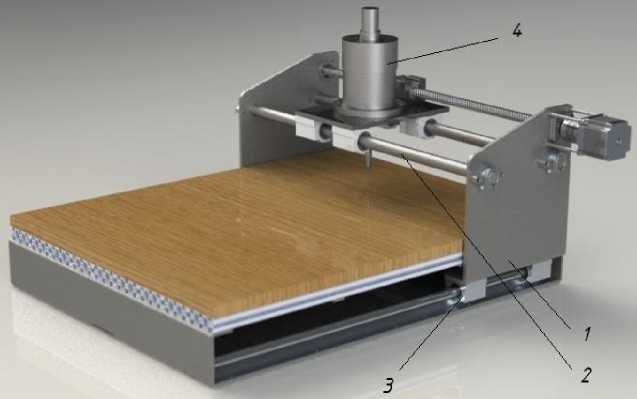
Figurе 2 - General look of a machine with two-coordinate movement system for perforating parts of the top of the shoe: 1 - frame; 2-system of moving in coordinate Y; 3-system of moving along the coordinate X; 4-line electric motor
Let us consider the technological operation of parts perforation and techniques of technological effort calculation.
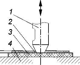
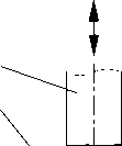
The scheme of the technological operation of materials perforation and the nature of the technological effort changes in the material during its execution are presented on the fig. 3. [1].
F perf
b
c
Figurе 3 - The scheme of the beginning (а) and the ending (b) of the technological operation of the light industry materials perforation and the nature of the changes in the technological perforation effort F in the material (c):
1 - puncher, 2 - material, 3 - cutter plate, 4 - base, A - thickness of the material; Fperf - technological effort required for the materials perforation
In case when the perforation is considered as a cut off by one puncher, multiplied by their number, the real effort value does not correspond to the calculation. This is due to the fact that we neglect factors, which are insignificant when cutting, but play a significant role in perforation.
These factors include: the geometric factor (the puncher perimeter, the influence of the opposite edge, size change of the carving), the effect of carving deformation, the cutting number in the puncher channel, etc.
As it is shown from the analysis of technical literature, in most cases, when design-ning equipment and calculating the required technological perforation effort for the implementation of certain technological operation, the empirical formula by Kapustin I.I. is used [1]:
where q - pipe cutting force, N/mm; L -perimeter of the puncher blade, mm; k -coefficient which takes into account the blunt blade of the puncher ( kA = 1,1 ^ 1,8 at the angle of the puncher sharpening в = 10 0 ^ 30 0 ); kp -coefficient which takes into account the angle of the puncher blade sharpening ( kp = 1,0 ^ 3,5 with the blunt size of the cutting edge of the puncher b = 0,1 ^ 0,5 mm ); kv - coefficient which takes into account the speed of the perforation process ( kv = 1 ^ 1,95 ); n - the number of punters.
But the calculation of the technological effort by this formula carries a notable error due to the large coefficients limits.
In order to improve the methodology of calculation, we conducted a series of experimental researches of the details perforation of the top of the shoes.
To calculate the technological perforation effort, a formula based on a known method for cutting effort calculating is used, but in the light of our research:
F perf = ( F™ • k» + P f ) • n . (2)
where Fcut - cutting force; kinc -coefficient of increase of perforation resistance with small perimeter cutters; P - extraction effort of carving from the puncher channel.
Cutting efforts are determined by the formula [4]:
F cut = kV • L •[ P • kw + 2 • t • ^ ten ' ( f + tg P ) ] ,(3) where p - the specific value of elastic resistance strength of the material; k – coefficient which takes into account the magnitude of cutter blade wearing; t - the thickness of the cutter immersion into the material before the ahead gap occurrence; ^en -tension of the material compression; f - friction coefficient between the puncher and the material.
On the basis of conducted experimental researches it was established that when cutting the openings of small perimeter there are factors that significantly increase the resistance of the cutter immersion into the material. It is found that the perforation force depends on the puncher perimeter. Using the puncher with the diameter up to 5 mm, it is necessary to enter the coefficient of perforation effort increase. It is also found that extra effort is required to extract the punching from the puncher channel. It depends on the perimeter, shape and length of the puncher output channel. Taking into account the abovementioned factors, it is possible to significantly improve the accuracy of the perforation effort calculation.
Let us consider the technological operation of parts and products marking and branding and the methodology for technological effort calculating.
Mechanical marking and branding of a material is a complex process that runs on different scale levels. The surface layer at the parts processing by marking is formed as a result of complex interconnected phenomena that arise in the field of deformation and in adjacent zones. These phenomena include the micro-and macrostructure of the material; microgeometry of the surface; change in strength and plastic properties of the material, which deforms under the loading influence; elastic and plastic deformations that arise repeatedly; thermal processes and friction that arise during the operation.
There are various mechanical methods of parts and products marking and branding. However, from all mechanical methods of marking with receipt of impressions on the surface of parts and products under the influence of the tool the most common, simple, affordable and economically justifiable are the shock method of marking and pressure marking [4]. Under the tool influence on the material, plastic deformation, its local seal and some ejection around the contour sign occur.
The method of pressure marking (static method) is based on the phenomenon of the material deformation as a result of immersion of the working part of the tool (marker head) into the material due to the gradually increasing effort.
In the static marking method, the tool acts on a surface that is machined with a certain constant force, undergoes a smooth singlewringing of the surface, which is processed without the action points moving. In this case, the inertial forces do not significantly affect the marking process.
Static method, as a rule, provides the technological process of marking with less action force.
Traditionally, while using the static marking method, the resistance characteristics of the plastic deformation of the material are used for determining the required loads.
The factors that influence the resistance to deformation when marking are the material properties, the tension state, the deformation degree, the deformation speed, the temperature.
The main marking parameters are as follows: elastic and plastic deformation in the hearth of deformation; contact area between marking head and the surface of the processed material; action force on instrument; the tension occurred from the applied effort; multiplicity of making effort.
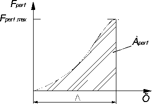
With static, as well as with the impact action on the processed surface, a stamp (impress-sion) from the marker head is formed. The scheme of the technological operation of parts and products marking and the nature of the deformation curve changes of the material during the marking operation are shown on the fig. 4. As can be seen from the curve, as the force F increases, the elastic deformation of the surface emerges, and then becomes plastic. The shaded area corresponds to the work required for the material deformation; it means the work F , required for the operation of parts and products marking.
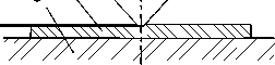
b
F mark
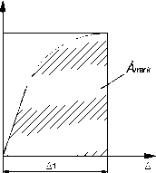
Figurе 4 - The scheme of the beginning (а) and the ending (b) technological operation of parts and products marking and the nature of the deformation curve changes of the material during the marking operation (c): 1 – tool; 2 – material; 4 – base; Δ - the depth of the tool immersion into the material; F - technological effort of marking
Technological effort of marking F defines the working conditions, design performance, power and energy characteristics of the equipment.
When performing the technological operation of marking or branding of parts and products made of different materials, with marking heads of different sizes on the equipment; it is needed to know the technological effort. Approximate figure of the effort, when marking and branding various parts and products, can be determined by the formula [4]:
F maik max S mark q sp (4)
where S - area of the working tool surface (marker head), mm2; q - specific pressure, N/mm2.
Impact marking method is based on the phenomenon of material deformation as a result of immersion in the material its working part of the instrument under the influence of impact [2].
While using impact method the tool influences once the entire processed surface or its part, herewith the action force F in each cycle varies from zero or from a certain point F to the maximum, and in the case of local impact, the hearth of deformation can consistently and evenly pass through the whole processed surface.
When using the impact method of the marking operation, the degree of hardening of the material increases, which is characterized by microhardness increasing, the values of compressive residual tensions and the thickness of the strengthened layer. Therefore, the impact method of marking compared with static, depending on the hardness of the material being processed, requires more energy. One of the reasons for this is that the higher the loading speed, the less the time of plastic deformation, and, accordingly, the higher voltage when the transition from elastic deformation to plastic one occurs.
The shock performance of the marking operation is determined by the impact energy E , which is applied to the material being processed, and the material deformation speed. In addition to the useful operations of deformation, the working part of the machine spends energy on the elastic bounce and overcoming frictional forces. Therefore, its potential energy in carrying out the operation of different materials marking should be on 10-20% more than useful operation of deformation.
When using the dynamic method of this technological operation, it is necessary to take into account the speed of the working body movement. In view of the fact that the linear electric motor of a machine with a two-coordinate system for performing the considered technological operations operates in a dynamic mode ( speed of the puncher movement up to 5 m/s), in our opinion, it is necessary to add the dynamic factor into the formula (4):
F , = S ,q k‘ C5f mark max markqsp v (5)
where k ‘ - coefficient, which takes into account the speed of the implementation process of the marking and branding technological operation
The interest of the dynamic factor for different materials will be different.
Conclusions
The developed mechatronic installation is a new tool that allows expanding the use of CNC devices in various industries, and also provides the moving of the actuator in a two-coordinate system along a complex contour.
The analytical expressions that bind together the technological effort, properties of the material, instrument parameters and the implementation speed of the operation are obtained during this research. The results of the study can be used to design the device or calculate the technological effort, necessary for the implementation of mentioned operations.
References The calculation of technological effort for impact perforation and parts and products marking
- Polishchuk О. The increasing of an effectti-veness of the use of the press-forging equipment in a light industry: The dissert.. Candidate of the Technical Sciences: 05.05.10. -К.: 2001. -155 p.
- Polishchuk О., Matushevskiy M., Musyal Ya., Kalachinskiy T. Classification of methods marking of parts and products in mechanical engineering and light industry. Modern technologies in mechanical engi-neering: Collection of scientific works./Com. Skyba M.E., Oleskandrenko V.P. -Khmelnytskyi: KHNU, 2018. -P.174-180.
- Polishchuk O., Karmalita A. Press equip-ment with linear electric engines: existing designs, characteristics and fields of use. W: edited by Shalapko J. and Zhultovski B.: Interdisciplinary integ-ration of science in technology, education and econo-my. Polish Mechanical Engineers and Technicians Association, Bydgoszcz -Poland, 2013. -P.165-171.
- Egorov A.A. Pulsed linear electromagnetic drive for marking and branding of parts and products: The dissert.. Candidate of the Technical Sciences: 05.09.03. -Saratov: 2007. -180 р.
