The choice of the energy parameters of an oxygen-hydrogen propellant expander cycle rocket engine

Author: Belyakov V.A.
Journal: Siberian Aerospace Journal @vestnik-sibsau-en
Section: Aviation and spacecraft engineering
Article in issue: 3 vol.23, 2022.
Free access
In liquid-propellant rocket engines (LRE), made according to a gas-free scheme, the turbine of the turbopump unit (TPU) is driven by heated fuel in the coolant system of the combustion chamber (CC). The absence of a gas generator greatly increases the reliability of the LRE and provides a number of advantages over other engine schemes. At the moment, the existing oxygen-hydrogen gasless liquid-propellant rocket engines do not meet mod-ern tactical and technical requirements for the level of thrust and pressure in the (CC) engine. Therefore, it is necessary to study ways to increase the energy parameters of the liquid-propellant rocket engine and identify promising engine schemes. This article proposes schematic solutions for an oxygen-hydrogen LRE, provides an analysis of the influence of various factors on the power parameters of the engine, as well as recommendations for the design of gasless LRE. A mathematical model for calculating the main energy and geometric parameters of the engine has been developed. Prospective pneumohydraulic schemes of an oxygen-hydrogen gasless liquid-propellant rocket engine are proposed, depending on the tactical and technical requirements.
Liquid-propellant rocket engine by expander cycle scheme, oxygen, hydrogen, turbopump unit, combustion chamber, specific thrust impulse of the engine, heat exchange intensification
Short address: https://sciup.org/148329639
IDR: 148329639 | UDC: 629.7.036.54 | DOI: 10.31772/2712-8970-2022-23-3-424-436
Text of the scientific article The choice of the energy parameters of an oxygen-hydrogen propellant expander cycle rocket engine
Intoduction
Nowadays, an urgent task is to increase the energy parameters of liquid-propellant rocket engines (LRE) as part of an interorbital transport vehicle (ITV), which serves to deliver payload to a geosynchronous orbit with the possibility of returning to low Earth orbit, as well as to launch spacecraft into interplanetary orbits.
Of greatest interest are oxygen-hydrogen rocket engines made according to a gas-free scheme. In such engines, only regenerative flow-through cooling by propellent СС (combustion chamber) is used. After cooling of the СС housing, the component is fed to the thrust of the turbine of turbopump unit of the oxidizer (TPUO) and propellant (TPUP). Due to such a hydrogen supply scheme, as well as its efficient performance, it is possible to realize high values of the adiabatic operation of the turbine, and, consequently, its power.
To ensure the required pressure in the combustion chamber in engines of this scheme, high-pressure and high-speed (50,000–130,000 r/pm) TPUP pumps are used. Therefore, the increase in the energy parameters of the engine, such as specific thrust impulse (STI), pressure in the combustion chamber, depends on [1–5]:
-
– engine configuration;
-
– thermal state of the combustion chamber and heating of the fuel component in the cooling path;
-
– energy parameters of TPU.
To solve the problems of launching a spacecraft (SC) into various orbits of the Earth and other planets of the solar system, it is necessary:
-
– to develop ITV units with a minimum dry weight;
-
– to provide for the possibility of multiple use of ITV;
-
– to implement a smooth launch into a geosynchronous orbit of large-sized space objects.
Achieving these requirements is possible through the use of a gas-free liquid-propellant rocket engines system (LRES), which has a number of advantages compared to other existing engine power schemes [6; 7], namely:
-
– increased reliability, simplified design and minimum dry weight of ITV units and systems;
-
– high efficiency due to the use of pre-chamber turbines to drive TPU pumps;
-
– no loss of STI for curtain cooling due to the use of only regenerative through-flow cooling.
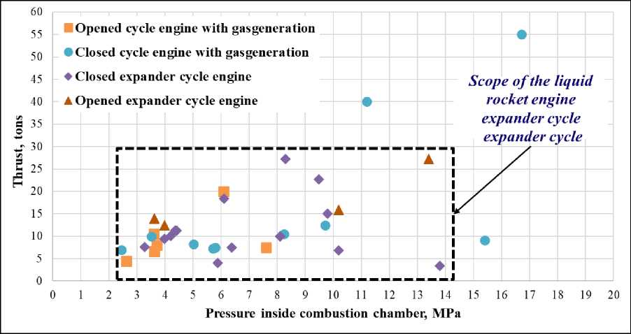
Analyzing the existing projects of gas-free rocket engines developed in the USA, EU, Russia and Japan (RL-10 and its modifications, RL-50, RL-60, Vinci, RD-0146 and its modifications, Hipex, AECE, MB-35, MB-60, LE-5 and its modifications), we can conclude that the use of a gas-free LRE scheme as part of the ITV is effective. Fig. 1 and 2 show the dependence of engine thrust on pressure in the CC of oxygen-hydrogen LRE for the upper and lower stages of launch vehicles (LV) and upper stages (US). Fig. 3 shows the dependence of the engine STI on the pressure in the CC of oxygenhydrogen LRE for upper stages.
As can be seen, the gas-free scheme is used for the upper stages of the LV and US. This is explained by:
-
– the possibility of providing up to 15 tf of engine thrust;
-
– high engine TPI;
-
– the use of LRE with pressure in the CC up to 15 MPa.
Existing liquid-propellant rocket engines of a gas-generator scheme have STI engine I sp = 465–475 s.
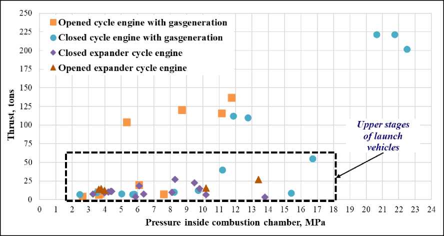
Рис. 1. Зависимость тяги двигателя от давления в КС кислородно-водородных ЖРД для нижних и верхних ступеней РН и РБ
Fig. 1. Dependence of engine thrust on the pressure in the CС of oxygen-hydrogen liquid-propellant rocket engines for the lower and upper stages of launch vehicles and upper stages
Opened cycle engine with gasgeneration
• Closed cycle engine with gasgeneration
♦ Closed expander cycle engine
A Opened expander cycle engine
Я 35
г 30
Scope of the liquid rocket engine expander cycle expander cycle
0 1 2 3 4 5 6 7 8 9 10 11 12 13 14 15 16 17 18 19 20
Pressure inside combustion chamber, MPa
Рис. 2. Зависимость тяги двигателя от давления в КС кислородно-водородных ЖРД для РБ
Fig. 2. Dependence of engine thrust on the pressure in the CС of oxygen-hydrogen liquid-propellant rocket engines for the lower and upper stages of upper stages
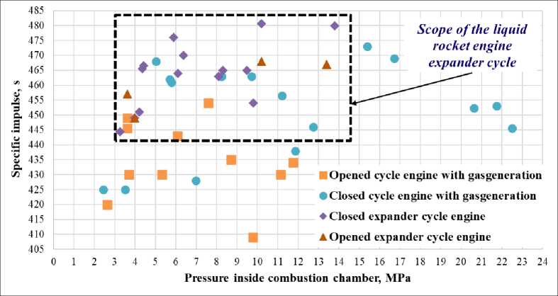
Рис. 3. Зависимость УИТ двигателя от давления в КС кислородно-водородных ЖРД для РБ
Fig. 3. Dependence of the specific thrust impulse of the engine on the pressure in the CС of oxygen-hydrogen LRE for upper stages
Such values of DPI are achieved:
-
– due to the use of high-enthalpy propellant (liquid oxygen + liquid hydrogen);
-
- due to the use of longer nozzles with a large degree of expansion sa (use of uncooled nozzles);
-
– an increase in pressure in the combustion chamber due to the intensification of heat transfer in cooling path.
Increasing the amount of heat transferred to the propellant in cooling path allows to increase the energy parameters of the engine. There are methods for efficient heating of a component that have advantages and disadvantages. In this case, the main task is to obtain the maximum heating of the propellant component with minimal hydraulic losses.
Methods for increasing propellant heating in a gas-free liquid-propellant rocket engine
High energy parameters of LRE are achieved not only by intensifying heat transfer in the cooling path, but also by supplying additional heat to the fuel with the help of:
-
– the use of a heat exchanger installed before the coolant enters the cooling path (for example, as it is implemented in the AECE engine);
–installation of a Field tube in the CC, in which the refrigerant after maintenance is additionally heated and then fed to the TPUO turbine drive (for example, as in the HIPEX engine);
-
– use of a reducing gas generator (not participating in the engine power supply circuit), which serves for additional fuel heating in a heat exchanger installed inside the gas generator.
The required heating of the fuel is also achieved by optimizing the design of the cooling path:
-
– variation of the geometric parameters of the fins and walls;
-
– change of fins thickness;
-
– elongation of the cylindrical part of the CC [3; 4];
-
– use of screw channels;
-
– application of additional fins on the side of the combustion chamber fire wall in order to increase the heat exchange area [7–10].
It should be noted that such solutions for intensifying heat transfer in coolant system can also adversely affect the energy parameters of the engine. This is due to an increase in hydraulic losses in the coolant system, not only due to design changes in the engine cooling system (losses due to friction and overcoming local resistance forces), but also due to a decrease in fuel density due to its heating in coolant system [11–13].
The hydraulic pressure loss of the fuel in the coolant system can be compensated by the required pressure of the high-speed TPUP pump [14–18]. Therefore, the high energy parameters of a gas-free liquid-propellant rocket engine are ensured by the maximum heating (limited by the melting point of the material in the coolant system) of the component in the coolant system, the required pressure of the TPUP pump (limited by the permissible rotor speed due to the performance of the bearings) or the minimum hydraulic losses in the coolant system [4; 6].
It should also be taken into account that with an increase in pressure in the combustion chamber at a fixed engine thrust:
– the heat flow to the fire wall of the CC increases [10; 19];
– the dimensions of the engine (diameter of the chamber, critical and outlet sections) and the total fuel consumption in the combustion chamber are reduced [2; 3; 6].
At the same time, the change in the total heat exchange area and heat flow in the combustion chamber has a greater effect on fuel heating in coolant system.
The energy parameters of the engine also depend on the properties of the propellent supplied to the combustion chamber [1; 8; 20]. Taking into account the change in the enthalpy of the propellent according to the conditions of its supply to the mixing head affects the temperature of the combustion products and the thermophysical properties of the mixture in the combustion chamber. For an oxygen-hydrogen gas-free liquidpropellant rocket engine, recalculation of the fuel enthalpy is based on the following features:
– supply of gaseous hydrogen after the drive of the TPUO and TPUP turbines to the mixing head of the CC;
– hydrogen compressibility;
– change in the properties of hydrogen and oxygen in terms of temperature and pressure (change in energy in pumps and turbines of TPU, in pipelines, control units, etc.).
Pneumohydraulic scheme of a gas-free oxygen-hydrogen liquid-propellant rocket engine
Fig. 4 shows the PHS of the LRE under consideration. A distinctive feature of this engine scheme from other gas generator-free schemes is the presence of separate TPU of the oxidizer (TPUO) and propellent (TPUP) with a turbogas extraction circuit from the input to the TPUO to the input in the mixing head CC. This circuit is designed to control engine thrust.
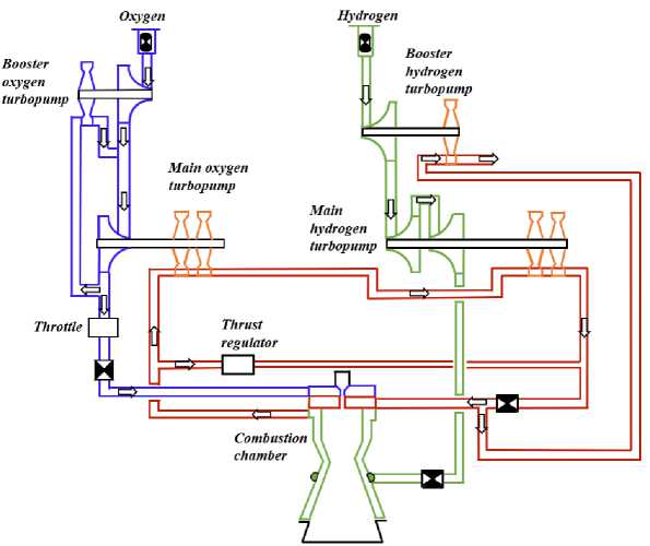
Рис. 4. Пневмогидравлическая схема безгазогенераторного ЖРД
-
Fig. 4. Pneumohydraulic scheme of the expander cycle liquid-propellant rocket engine
Cavitation-free operation of the main TPUP and TPUO pumps is provided by booster turbopump units (BTPU) installed on the O and G lines. The booster turbopump oxidizer unit (BTPUO) is driven by a portion of the oxygen flow taken from the output of the main TPUO pump.
The TPUO and TPUP turbines are fed by gaseous hydrogen heated in the coolant system, part of which, before entering the mixing head of the CC, is directed to the turbine drive of the booster turbopump propellent unit (BTPUP). After the BTPUP turbine, the exhaust gas is discharged overboard or fed to the pressurization of the "G" tank.
Statement of the problem of calculating the STI of an oxygen-hydrogen gas-free liquidpropellant rocket engine
In this paper, we consider ways to increase the engine STI by increasing the pressure in the combustion chamber (with a fixed engine thrust and the ratio of fuel components), and, consequently, the temperature in the CC, by intensifying the heat transfer in the coolant system. This is necessary for greater heating of hydrogen in order to increase the power of the TPUO and TPUP turbines.
Based on the diagram in Fig. 4, a mathematical model has been developed that describes the working processes of the engine. With the help of a mathematical model, the parameters of a gas generator-free liquid-propellant rocket engine with a thrust of P eng = 10 tf and a ratio of fuel components k m = 6.08 were obtained. In this case, the pressure in the CC was taken in the range p cc = 6…15 MPa. As a first approximation, the engine TPI was taken equal to I уд = 463 s.
Based on the results of the calculation, promising circuit solutions have been identified that provide high energy parameters for a gas-free liquid-propellant rocket engine.
Mathematical model
Fig. 5 shows a structural-functional block diagram of a quasi-static model of a gas-free liquidpropellant rocket engine. The model is based on the equations of hydraulics, gas dynamics, heat and mass transfer, thermal protection and cooling of the LRE chamber housing, calculation of TPU and BTPU units and their characteristics.
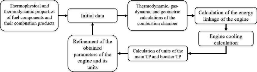
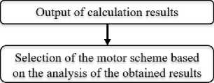
Рис. 5. Структурно-функциональная блок-схема квазистатической модели
-
Fig. 5. Structural-functional block diagram of the mathematical model
The developed mathematical model is implemented in the Python programming language. It includes the following main software modules:
– a module for calculating the basic engine scheme to obtain initial data and search for the optimal scheme of a gas-free liquid-propellant rocket engine;
– calculation of engine parameters in the range of thrusts and pressures in the combustion chamber;
as well as auxiliary:
– a module for hydraulic calculation of TPU and BTPU units and obtaining their reduced characteristics;
– calculation of gas-dynamic, thermophysical and thermodynamic parameters.
Calculation results for a gas-generator oxygen-hydrogen liquid-propellant rocket engine
To achieve the energy balance of the LRE scheme under consideration in the pressure range in the combustion chamber, it is necessary to find the required mass flow rate of the working fluid on the TPUP turbine, taking into account the calculation of the thermal state of the combustion chamber. Figure 6 shows the dependence of the mass flow rate of the working fluid on the TPUP turbine on the hydrogen temperature after coolant system in the range of pressure in the combustion chamber and the rotational speed of the TPUP rotor n TPUP = 125,000 r/pm.
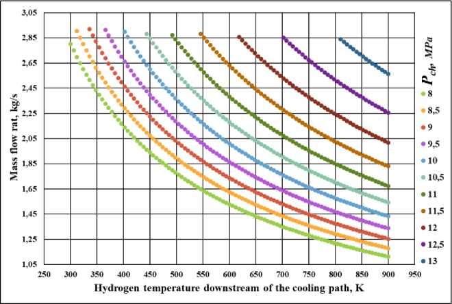
Рис. 6. Зависимость массового секундного расхода на турбине ТНАГ от температуры водорода после ТО при различном давлении в КС
-
Fig. 6. Dependence of the mass flow rate on the TPAF turbine on the temperature of hydrogen after the cooling jacket at different pressures in the combustion chamber
From the dependence in Fig. 6 it can be seen that for each value of hydrogen heating in coolant system, at a certain pressure in the combustion chamber, there is such a mass flow rate per second at which the engine circuit is energetically linked. At the same time, it must be borne in mind that when the pressure in the combustion chamber varies, the following parameters of the engine and its units change [3; 6; 8; 15]:
– geometric and energy parameters of the CC;
– hydraulic losses along the lines of the oxidizer and fuel (losses in highways, control units, in coolant system, etc.);
– required flow rate of the working fluid to drive the BTPU turbines;
– full efficiency of the TPU and BTPU units;
– rotor revolutions of TPU.
In order to achieve a high STI of the engine by intensifying heat transfer in the coolant system, it is also necessary to take into account the thermal stress of the combustion chamber. It is limited by the melting temperature of the material used for the fire wall of the chamber [11; 12; 21].
Let's transfer the received points to Fig. 6, corresponding to the minimum hydrogen heating temperature, in Fig. 7. As mentioned earlier, the pressure in the CC also depends on the pressure of the TPUP pump. Therefore, Fig. 7 shows the results of calculations for different numbers of revolutions of the TPUP rotor.
Рис. 7. Зависимость температуры водорода после РО от давления в КС при различном числе оборотов ротора ТНАГ
-
Fig. 7. Dependence of the hydrogen temperature after the cooling jacket on the pressure in the combustor at different speeds of the TPUP rotor
On Fig. 7, the dotted line marks the boundary for the maximum possible heating of hydrogen in the coolant chamber, depending on the pressure in the CC and the number of revolutions of the TPUP rotor. It should be noted that with an increase in the pressure in the combustor (from 8 MPa and more), the limitation on hydrogen heating in the coolant chamber shifts slightly (by 10–15 K) and, to generalize the obtained data, the temperature curves in Figs. 7 are connected by one line.
Circuit solutions
Based on the obtained dependencies shown in Figs. 6 and 7, recommendations on circuit solutions of the considered gas-generator LRE with fixed engine thrust P eng = 10 tf and fuel component ratio k eng = 6.08 are revealed.
For the pressure in the combustion chamber pk ≤ 8 MPa and the TPUP rotor speed n TPUP ≤ 115000 r/pm, the standard engine diagram shown in Fig. 4, satisfies the requirements for providing the necessary TPI I pef = up to 463 s.
Increasing the TPUP rotor speed to n TPUP = 125,000 allows using a more profitable scheme (Fig. 8) with additional hydrogen bypass for the TPUP turbine. This scheme provides the engine STI I spec = up to 467 s at a pressure in the CC pk ≤ 8.5 MPa. The presence of an additional bypass of turbogas from the input to the TPUP to the input to the mixing head of the CC is explained by the excessive power of the turbine. Therefore, the circuit shown in Fig. 8, according to the dependencies in Fig. 7 is more beneficial if:
-
– hydrogen temperature after coolant system is less than T exit cool. syst. < 350 K at TPUP rotor speed n TPUP ≤ 115000 r/pm;
-
– hydrogen temperature after coolant system is less than T exit cool. syst. < 315 K at TPUP rotor speed 115000 r/pm < n TPUP ≤ 125,000 r/pm.
Achieving a higher pressure in the CC pк > 8.5 MPa is implemented by the scheme shown in Fig. 9. Depending on the number of revolutions of the TPUP rotor, the pressure in the CC and the tempera- ture of the turbine working fluid, hydrogen after TPUO is taken from the TPUP inlet to the input to the mixing head of the CC or is taken after coolant system to the TPUP inlet.
At rotor speeds n TPUP > 125,000 r/pm and pressure in the combustion chamber 8.5 MPa < p c ≤ 10.5 MPa, the power of the TPUP turbine may turn out to be excessive due to the deprivation of hydrogen heating in the coolant system T exit cool. syst. = 300 ... 400 K. But with a further increase in pressure in the CC p c > 10.5 MPa, the achievement of the energy balance of the TPUP units is carried out by adding a small amount of hydrogen through the bypass line installed between the outlet from the coolant system and the TPUO turbine, as shown in Fig. 9.
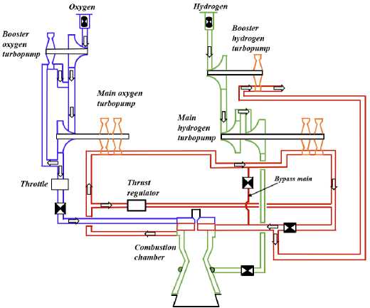
Рис. 8. Схема безгазогенераторного ЖРД с дополнительным отбором турбогаза со входа в ТНАГ на вход в смесительную головку КС
Fig. 8. Scheme of an expander cycle liquid-propellant rocket engine with additional turbogas extraction from the TPUP inlet to the CC mixing head inlet
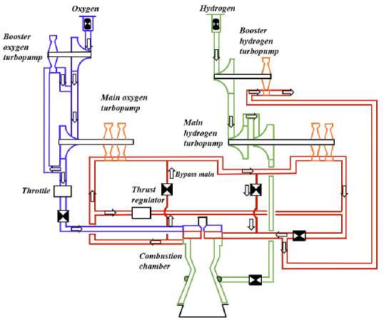
Рис. 9. Схема безгазогенераторного ЖРД с дополнительным отбором турбогаза с выхода из тракта охлаждения (или со входа в ТНАГ) на вход в ТНАГ (или на вход в смесительную головку КС)
-
Fig. 9. Scheme of an expander cycle liquid-propellant rocket engine with additional turbogas extraction from the exit from the cooling path (or into the TPAF) to the inlet to the TPAF (or to the inlet to the mixing head of the compressor station)
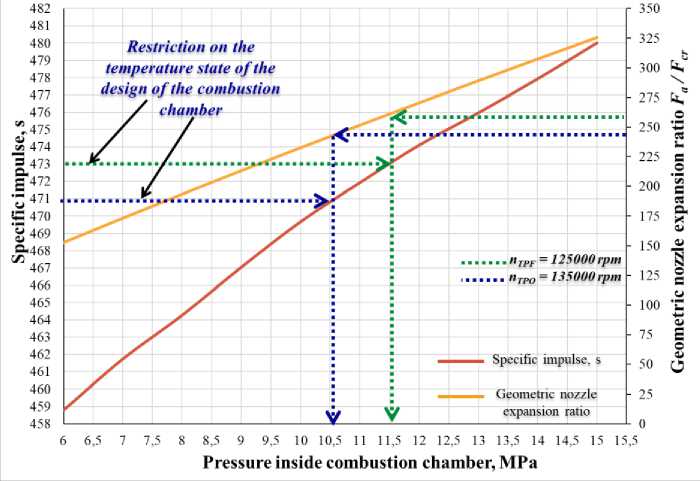
Рис. 10. Зависимость УИТ и геометрической степени расширения сопла безгазогенераторного ЖРД от давления в КС
-
Fig. 10. Dependence of the specific thrust impulse of the engine and the geometric degree of expansion of the nozzle of an expander cycle liquid-propellant rocket engine on the pressure in the combustion chamber
As a result of optimizing the engine parameters, it was found that the maximum STI (Fig. 10) is I spec = 473 s with the following parameters:
– pressure in the CS p c = 11.5 MPa;
– the number of revolutions of the TPUP rotor n TPUP = 135,000 r/pm;
– geometric expansion ratio of the nozzle ε a = 260.
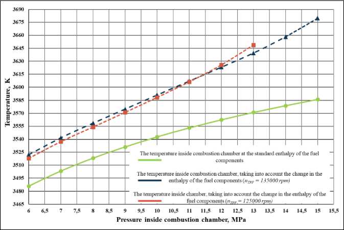
Рис. 11. Зависимость температуры продуктов сгорания в КС от давления в КС с учетом изменения энтальпии компонентов топлива
-
Fig. 11. Dependence of the temperature of combustion products in the combustion chamber on the pressure in the combustion chamber, taking into account the change in the enthalpy of the fuel components
In this case, the temperature in the CC, according to the dependences in Fig. 11 was T cc = 3615 K, and the hydrogen heating temperature in the coolant system was T exit cool. syst. = 460 K (see Fig. 7). The limitation on the temperature of hydrogen heating in coolant system is explained by the high temperature of the fins installed on the fire wall of the chamber T f = 950…1050 K [9; 7; 21]. Therefore, a decrease in the TPUP rotor speed shifts the maximum pressure in the CC and TPI to lower values (see Fig. 10: dotted lines) due to the difficulty in ensuring reliable cooling of the CC and achieving an energy balance in the engine circuit.
From the graph in Fig. 11 it can be seen that the change in the thermophysical properties of the fuel entering the mixing head significantly affects the temperature of the combustion products in the combustor. But an increase in the TPUP rotor speed, i.e., an increase in the pressure of the TPUP pump, with the same heating of hydrogen in the coolant system, slightly affects the temperature change in the combustion chamber (Δ T cc = 5...7 K).
It should be noted that the results of calculations (see Fig. 7, 10, 11) for a pressure in the combustion chamber of more than 11.5 MPa are achievable by supplying additional heat to the fuel or by increasing the speed of the TPUP rotor by more than 135,000 r/pm (at it is necessary to evaluate the realizability of such values). In the same formulation of the problem, we can assume that further intensification of heat transfer in coolant system leads to a more heat-stressed and less reliable engine.
Conclusion
The following conclusions can be drawn:
-
1. As a result of calculating the parameters of a LRE with a thrust of 10 tf in the pressure range in the combustion chamber from 6 MPa to 15 MPa, circuit solutions have been identified that provide an engine specific thrust impulse of 473 s.
-
2. For a pressure in the combustion chamber from 6 to 8.5 MPa, the specific thrust impulse of the engine is 460–467 s.
-
3. Achieving a higher pressure in the combustion chamber (more than 8.5 MPa) is possible when using a scheme with additional extraction (in addition to extraction to the thrust regulator) of turbogas from the inlet to the TPUP to the inlet to the mixing head of the combustion chamber (or from the outlet of the coolant system to entrance to TPUP). In this case, the pressure in the combustion chamber is 11.5 MPa, and the specific thrust impulse of the engine is 473 s.
-
4. Further increase in the energy parameters of a gas-free liquid-propellant rocket engine with thrust 10 tf and pressure in the CC more than 11.5 MPa is possible due to the supply of additional heat to fuel through the use of a heat exchanger installed in front of the inlet into the engine coolant system or as part of a reduction gas generator, as well as a Field tube inserted into the combustion chamber.
References The choice of the energy parameters of an oxygen-hydrogen propellant expander cycle rocket engine
- Dobrovolsky M. V. Zhidkostnye raketnye dvigateli. Osnovy proektirovaniya [Liquid rocket engines, Fundamentals of design]. Moscow, Bauman Moscow state technical University Publ., 2016, 461 p.
- Kalmykov G. P., Lebedinskiy E. V., Tararyshkin V. I., Eliseyev I. O. Bezgeneratornyy ZHRD tyagoy 200 t.s. na uglevodorodnom goryuchem [Generatorless rocket engine thrust 200 t.s. on hydro-carbon fuel]. Proceedings of 4th International Conference on Launcher Technology “Space Launcher Liquid Propulsion”, Liege (Belgium), 3-6 december, 2002, pp. 2–9. URL: https://el.b-ok2.org/dl/3136783/f689d5 (date of the application: 10.06.2019).
- Kalmykov G. P., Lebedinskiy E. V., Tararyshkin V. I. Kompyuternyye modeli zhidkostnykh raketnykh dvigateley [Computer models of liquid-propellant rocket engines]. Moscow, Mashinostroyeniye Publ., 2009, 376 p.
- Belyakov V. A., Vasilevskiy D. O. [Perspective circuit solutions of liquid rocket engine by ex-panded cycle]. Vestnik PNIPU. Aerospace science. 2019, Vol. 58, P. 69–86. Doi: 10.15593/2224- 9982/2019-58-06.
- Belyakov V. A., Vasilevskiy D. O., Ermashkevich A. A., Kolomencev A. I., Farizanov I. R. De-velopment of the concept of a reusable liquid rocket engine with three-component fuel. Siberian Aerospace Journal. 2021, Vol. 22, No. 1, P. 121–136. DOI: 10.31772/2712-8970-2021-22-1-121-136.
- Lebedinsky E. V. et al. Rabochie processy v zhidkostnom raketnom dvigatele i ih modelirovanie [Working processes in a liquid rocket engine and their modeling]. Moscow, Mashinostroenie Publ., 2008, 512 p.
- Gakhun G. G. Konstruktsiya i proyektirovaniye zhidkostnykh raketnykh dvigateley [Design and engineering of liquid rocket engines]. Moscow, Engineering Publ., 1989, 424 p.
- Berezhinsky R. A., Sokolov S. A., Gudkova S. R. et al. Modelirovanie rabochih processov i konstruktsiya elementov kamery ZHRD [Modeling of working processes and construction of elements of the LPRE chamber]. Voronezh, VGTU Publ., 2002, 169 p.
- Gakhun G. G., Alekseev I. G., Berezanskaya E. L. et al. Atlas konstruktsiy ZHRD [ATLAS of LPRE design, Part 1]. Moscow, MAI Publ., 1969, 286 p.
- Naraghi M. H., Dunn S., Coats D. Dual regenerative cooling circuits for liquid rocket engines (Preprint). 42nd AIAA/ASME/SAE/ASEE Joint Propulsion Conf. & Exhibit. 9 July – 12 July 2006, Sac-ramento, California. AIAA 2006-4367. 2006. P. 1–18.
- Ievlev V. M. Turbulenthoye dvizheniye vysokotemperaturnykh sploshnykh sred [Turbulent mo-tion of high-temperature continuous media]. Moscow, Nauka Publ., 1975, 255 p.
- Ponomarenko A. RPA: Tool for Rocket Propulsion Analysis, Thermal Analysis of Thrust Chambers. Available at: http://propulsion-analysis.com/downloads/2/docs/RPA_ThermalAnalysis.pdf (accessed: 10.10.2020).
- Belyakov V. A., Vasilevskiy D. O., Ermashkevich A. A., Kolomencev A. I., Farizanov I. R. Design of the cooling system of a reasuble liquid rocket engine with three-component fuel. Siberian Aerospace Journal. 2021, Vol. 22, No. 2, P. 316–327. DOI: 10.31772/2712-8970-2021-22-2-316-327.
- Horlock J. H. Osevyye turbiny (gazovaya dinamika i termodinamika) [Axial turbines (gas dy-namics and thermodynamics)]. Moscow, Mashinostroyeniye Publ., 1972, 211 p.
- Ovsyannikov B. V., Borovsky B. I. Teoria I raschet rabochih agregatov pitania jidkostih raketnih dvigatelei [Theory and calculation of power units for liquid rocket engines]. Moscow, Mashinostroyeniye Publ., 1986, 375 p.
- Korpela S. A. Principles of turbomachinery. Hoboken, New Jersey, 2011. 467 р.
- Oskar J. Haidn. Advanced rocket Engines. Germany: German Aerospace Center (DLR), 2008. 40 р.
- Oskar J. Haidn. On the effect of axial turbine rotor blade design on efficiency: a parametric study of the Baljé-diagram. Germany: German Aerospace Center (DLR), 2017. 15 р.
- Hobler T. Teploperedacha i teploombenniki [Heat transfer and heat exchangers]. Leningrad, Goskhimizdat Publ., 1961, 821 p.
- Kudryavtsev V. M., Vasilyev A. P. Osnovy teorii i rascheta zhidkostnykh raketnykh dvigateley [Fundamentals of the theory and calculation of liquid rocket engines]. Moscow, Vysshaya shkola Publ., 1975, 656 p.
- Aleksandrenkov V. P. Raschet naruzhnogo protochnogo okhlazhdeniya kamery ZHRD [Calcu-lation of external flow-through cooling of the LPRE chamber]. Moscow, Bauman Moscow State Technical University Publ., 2012, 74 p.
