The Control and Modeling of Diesel Generator Set in Electric Propulsion Ship

Author: Le Luo, Lan Gao, Hehe Fu
Journal: International Journal of Information Technology and Computer Science(IJITCS) @ijitcs
Article in issue: 2 Vol. 3, 2011.
Free access
This paper analyzes the characteristics of power system on electric propulsion ship. The mathematical model and simulation model of diesel engine PID speed control system and synchronous generator’s AVR+PSS excitation control system was built. At last the simulation test of suddenly add load was did in MATLAB/simulink environment. The result shows that the speed control and excitation control system has well stability, rapidity and some robustness.
Generator, Excitation, MATLAB/Simulink, Speed Control
Short address: https://sciup.org/15011614
IDR: 15011614
Text of the scientific article The Control and Modeling of Diesel Generator Set in Electric Propulsion Ship
Published Online March 2011 in MECS
Index Term — Generator, Excitation, MATLAB/Simulink, Speed Control
I . INTROUDUCTION
Power system of electric propulsion ship is much more complex than traditional ship. Electric propulsion ship makes electric propulsion and daily electric equipment is combined to form a comprehensive power system, which brings difficulties to transmission, distribution and power management. But electric propulsion has its own advantages, such as high propulsion efficiency, high economical efficiency and strong manipulative etc. Especially with high power frequency conversion governor, electric propulsion in commercial and military field is successful applications. The research of power system also begins to pay close attention to the impact of power quality problems.
Marine power system is mainly generating system, distribution system and electric system structure. The marine power station is the heart of generating system and an important component of ship. With the generator single-machine capacity increasing constantly, marine power system is more and more complicated and requirements of control system are increasingly high, the long term stability and quality of marine power control system is increasingly important. In the operation of power system, excitation current of the synchronous generator is the main source of reactive power, sometimes even is the only source. So whether normally, or in accident cases, characteristics of synchronous generator excitation control system is very important for the operation of power station.
In order to validate effective and stability for control method of speed control system and synchronous generator excitation system, this paper research the modeling and simulation of power generation subsystem control process, which to ensure the normal operation of the synchronous generator.
-
II. STRUCTURE OF MARINE DIESEL GENERATING SET MODELING
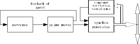
Marine diesel generating set is made up of diesel prime mover, speed governor, generator and compound excitation transformer. Block scheme of system structure shown as figure1. From figure 1, we can see this system has two closed-loop feedback control system: speed feedback control system (figure 2) and excitation feedback control system (figure 3). Reunification together these two system, it becomes to figure 4.
reliably, the grid frequency constant is essential. Grid feedback of excitation
power grid
Fig. 1 Block scheme of diesel generator set system structure
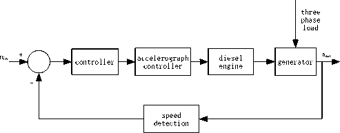
Fig. 2 Diesel engine speed feedback control system
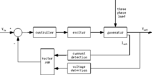
Fig. 3 Generator excitation feedback control system
frequency constant can ensure the speed control of induction motor and synchronization generator. And grid frequency is decided by speed of in net diesel generator sets. Speed control system of diesel generator set also directly affect active power output of generator. For the control of marine generator excitation system, its control character also directly affecting the quality of power supply. Excitation system control will directly influence the voltage stability of ship’s grid and reactive power output of generator.
Ⅲ. MODELING OF DIESEL ENGINE AND GOVERNING SYSTEM
In diesel generator sets, diesel engine is the main purpose of providing impulsion. No automatic speed control of diesel engine oneself ability, thus it must furnish governor. The purpose is ensuring that the diesel engine can be specified speed to stable operation.
In this paper, the combination of diesel engine and governor is used second-order to modeling. The simulation model is shown as figure 5.
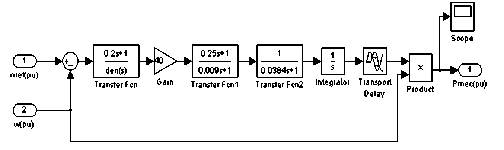
Fig. 5 Simulation model of diesel engine governor
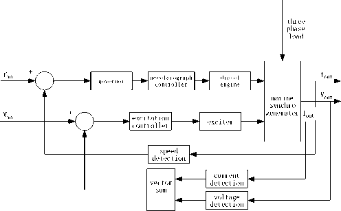
Fig. 4 Frequency and voltage of generator feedback control system
Speed feedback system detecting generator speed quantity, and the compound excitation transformer of excitation feedback system detecting terminal voltage of generator and output current. For power system run
In figure 5, ωef (pu) is per unit of the input speed setting value, ω(pu) is per unit of generator set actual speed which is tested through generator detection unit, Pmec(pu) is per unit of diesel engine output power, used to drive generator. The main controller and scale-up unit constitute the proportion, differential and second-order inertial link control unit which by adjusting the diesel engine accelerator actuators to speed adjustment effect. Output speed of diesel engine is through integral unit conversion for torque. Because diesel engine is a large time delay system, the torque first through delay unit then multiplied the speed signal of multiplier to reach machinery power signal. The torque power drives generator give out power [1].
W. THE FUNCTION OF SYNCHRONOUS GENERATOR EXCITATION SYSTEM
Excitation system is the important segment to ensure the voltage accuracy of generation and improve the stable operation of power system. In the power station, excitation control system is the basic and essential component. For various perturbation of marine power system, load charge is the main reason to caused ship voltage fluctuation. From theory analysis, load changes including the change of load current amplitude and power factor. No matter which kinds of changes can cause of generator armature reaction produces change, and then resulting in generator voltage change. Because ship load is more sensible, and voltage variation is mainly caused by the direct axis armature reaction, so load amplitude greaten or power factor reduced will cause terminal voltage drop. Oppositely will cause terminal voltage rises. The control for these changes is closely linked to excitation control system. Therefore requires excitation system has well stability, quickly response and strong adjust ability.
Summarized speaking, the function of excitation control system mainly in the following aspects [2]:
-
1) Maintain generator terminal voltage constant
Usually when load changes, generator terminal voltages will change, according to the change of terminal voltages adjusting generator excitation current, to make the terminal voltage maintain in certain level.
-
2) Control reactive power allocation of parallel operation generator
When two or more than two parallel synchronous generators running, automatic excitation device should guarantee the reactive power proportional distribution according to generator capacity, to prevent individual unit current over-load and improve total efficiency. Parallel unit reactive current not proportional distribution lies in the P.U. parameter of Parallel generation and excitation system is inconsistent. The P.U. inconsistent of excitation system is especially conmen. Therefore excitation system should have functions of reactive current distribution and stable, to overcome reactive
circulation of generator armature circuit arise by this parameter inconsistent.
-
3) Effectively improve system static stability
So-called static stability essence is the operating point stability. Usually refers to the steady-state or the ability of generator through the transmission system steady conveying power in small disturbance.
-
4) Improve system transient stability
Power system transient stability means in the major interference (such as the three-phase short-circuit, resection lines, etc.), ability of generator or local system in first swing or second maintain system does not lose synchronization with other part.
V. MATHEMATICAL MODEL OF SYNCHRONOUS GENERATOR EXCITATION SYSTEM
A Mathematical Model of Synchronous Generator
Synchronous generator is the core of marine power system, it integrates rotation and rest, electromagnetic change and mechanical at an organic whole, convert the mechanical energy into electricity, and then supply the whole marine power system. Marine power system stability is to a large extent make parallel operation of synchronous generators to keep synchronous.
In the widely used mathematical model of synchronous generators, general increase equivalent damping windings on rotor d and q shaft to improve the precision of mathematical model [3].
A d Aq _ A _
cos #
sin #
cos # - 2 ! )
sin # - T)
cos # + 2 ! ) - sin # + 2 П )
A a
A b
A c
( 1 )
Considering the influence of rotor self-induction and mutual inductance, park transformation is used when built mathematical model of synchronous generator. To simplify the analysis and calculation process, differential equation (abbreviated) is converted to constant coefficient equation with this transformation. Formula (1) shows the relation of park transformation. And some assumptions are made as follows:
-
1) Ignore speed variations influence for EMF, assumption ω =1;
-
2) Only consider positive sequence component influence for generator transient process, and omit zero axial magnetic chain voltage equation of park equations.
-
3) Don't consider damping winding transient process of q axis.
Get 5th order ordinary differential equation (vector format) of synchronous generators under d-q coordinates. Voltage equation as
|
L |
V d " V q V fd V id V . F |
[ Rs 0 = 0 0 L 0 lux |
0 R s 0 0 0 equat |
0 0 R fd 0 0 ions |
0 0 0 Rid 0 as |
0 " 0 0 0 R.q _ |
Г - 1 .fd 4d _ i q . |
+ |
■ P » d " рфч p ф fd Р Ф и _ Р Ф Ч _ |
+ |
0 0 . 0 . |
( 2 ) |
|
|
" Ф |
"1 |
" L d |
0 |
Lmd |
Lmd |
0 " |
d " |
||||||
|
Ф |
0 |
L q |
0 |
0 |
Lmq |
q |
( 3 ) |
||||||
|
^ |
d = |
L md |
0 |
Lfd |
Lmd |
0 |
ifd |
||||||
|
9 k |
d |
Lmd |
0 |
L md |
L kd |
0 |
г kd |
||||||
|
_^ k |
q j |
_ 0 |
L mq |
0 |
0 |
L kq _ |
L i kq _ |
||||||
|
In formula: |
|||||||||||||
|
Subscript: d / q |
— |
Axis; |
m |
Mutual |
inductance ; |
||||||||
f — Field winding ; k — Damping winding ; r —
Rotor ; s — Stator.
V x —Voltage ; R x —Resistance ; i x —Current ; ^ x —
Magnetic flux ; to x —Angular velocity ; p —Differential
d operator — , L — Inductance , to — Rotor angular dt x r velocity;
B Mathematical Model of Excitation System
-
a. Model of the Phase-compounding Excitation System
The phase-compounding excitation system is consisting of phase-compounding excitation unit, AC exciter and AVR. This paper reference IEEE (Institute of Electrical and Electronics Engineers)recommended exciter model to establish model of phase-compounding AC excitation system [4].
-
1) The model of phase-compounding excitation system is expressed d, q component:
U r = V ( Urf - Kl q X ) 2 + ( U q + KIdX ) 2 ( 4 }
In formula: Ur — The output voltage of the phase-compounding excitation unit;
Ud —The armature terminal voltage of the generator d axis;
U —The armature terminal voltage of the generator q q axis;
K = 9V2 П
;
x — The reactance of moving direction.
-
2) The voltage difference model
A U = U rf + U f 0 / K a - U f + U stab - U ff
X = V (U, ) 2 + (U q ) 2 • -1-
-
L 1 + sT r (5)
In formula: Uref — The reference voltage of automatic voltage regulator;
Ustab — Grounding-zero voltage;
U f 0 — The initial value of excitation voltage;
Ka — The effective gain of exciter;
Tr — The time constant of low-pass filter;
U ff — The output voltage of feedback loop;
A U —the voltage difference signal of comprehensive post.
-
3) The compensator model
U = A U 1 + T (6)
c 1 + sTb
In formula: Uc — The output voltage of compensator;
Tc — The time constant of compensator lead compensation;
Tb — The time constant of compensator lag
In formula: Kf — The feedback loop gain;
compensation.
4) The amplifier model
Tff — The time constant of feedback loop.
U
= Uc—— c 1 + sT a
In formula: Ua — The output voltage of amplifier;
The simulation model of phase-compounding excitation brushless alternating current excitation system, which is built by mathematic model introduced above, is shown as figure 6:
Ka — The gain of amplifier;
Ta — The time constant of amplifier.
5) The model of proportional saturation loop
E fd = U + U r (8)
0 ^ E f ^ E f max , and E f = E ^ .
Cons tan t , K p = 0
.K p V f , K p ^ 0
In formula: Efd — The output voltage of voltage regulator (the combining function of voltage difference regulation and phase-compounding excitation regulation);
Ef — The output voltage of proportional saturation loop;
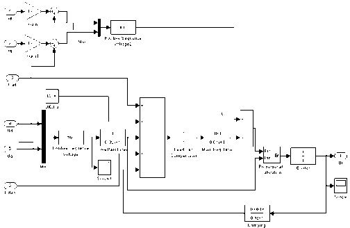
Fig. 6 Simulation model of AVR excitation regulator
E, 4
f max
Ef max — The max output voltage of proportional
saturation loop.
6) The mathematic model of alternating current exciter
After simplification, the mathematic model of alternating current exciter can be expressed in first-order loop, as follows:
U
f =
1 E
T e + K e fd
In formula: Ke — The time constant of alternating
b. The Control Model of PSS
PID excitation control method based on the classical control theory was widely applied, but this control method cannot achieve better excitation control performance, and cannot solve low frequency oscillation problem of the power system. So this paper adopts AVR + PSS (power system stabilizer) excitation control method. It is in the form of construction on the basis of AVR append an assistant calibration link PSS, thus constituted AVR + PSS excitation control mode. AVR unit of AVR + PSS excitation control system is calculated using the PID regulating mode. And PSS is mainly used to solve power system frequency oscillation. Also as a assistant calibration, it can improve excitation system control performance [5].
Excitation system and generator winding have characteristics of phase lag, the lag phase Angle can be expressed as [6]:
current exciter.
7) The feedback-stability loop
ф = - tg - 1
U
ff
= Uf
sKf
1 + sT ff
^
2^x X — ® x
1 - ( — )2 ® x
( 11 )
In formula: to — Low frequency oscillation
4. SIMULATION TEST frequency, tox K6KA T‘0 Ta
T a + K 3 T ‘ 0
2 K 3 V T ‘ 0 T a K 6 K a
KA > TA respectively represent the gain and inertia time constant of excitation system transfer function
G e ( ^ ) =
1 + T a S
. K 3
X d + X e К X e X
, K = , X
X d + X e 6 X d + X e ‘
— reactance of transmission line.
To offset this lag Angle ф, PSS must have advanced link. Usually advance link is two levels, its transfer function can be expressed as:
We did Simulation test in MATLAB/simulink environment. Simulation parameters Settings: rated output power of synchronous generators is 3MW; Rated voltage is 450V; Frequency is 50Hz; Resistance of generator Rs =0.0028 Ω; Excitation voltage reference is 1pu; rotor angular velocity is 1pu.
Other standard parameters of synchronous generators:
Xd = 1.305 X ’ = 0.296 X" d = 0.252
; ;;
Xa = 0.474 X ’ = 0 X" = 0.243 T d = 1.01
-
q qq
; ;
T d = 0.053 ; t ; = 0.13 ; p = 4
G ( s ) =
1 + Ts 1 + Ts --— X--—
1 + T 2 s
1 + T 4 s
( 12 )
When T1=T3 , T2=T4, expressed as follows:
the above formula can be
G ( s ) =
' 1 + T i s
( 1 + T 2 s J
( 13 )
According to above mathematical model, PSS
simulation model as figure 7 shown:
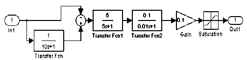
Fig. 7 Simulation model of PSS
Put PSS module is added to the figure 1, we complete the AVR + PSS excitation system establishment. As Fig. 8 shown:
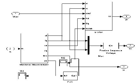
Fig. 8 AVR + PSS excitation system establishment
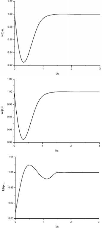
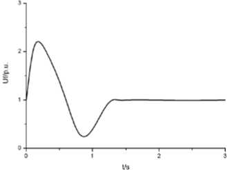
Fig. 9 Response of the system when suddenly add 100% static load
Figure 9 presented the dynamic characteristic curve when system starting with suddenly add 100% static load. Curves including four variables: power-angle, angular velocity, voltage Ut , excitation voltage U f . From
Fig.4, we know when suddenly add 100% static load, the system dynamic voltage variation ф = 12% , stable time T = 1.5 s, dynamic speed variation ф = 7% , stable time T = 2.5 s.
W CONCLUSION
The excitation control of synchronous generator and speed control of diesel engine on marine power station is the important means in improving marine power system stability. From the result of simulation experiment, we know that dynamic characteristics of speed control and AVR + PSS excitation control system completely meet the requirements. When power system with load operates, the response of controller is quicker and the robustness is better. The mathematical model of diesel generator set in Electric Propulsion Ship contributes to the foundation of further research on marine power system.
References The Control and Modeling of Diesel Generator Set in Electric Propulsion Ship
- Iwai Tomohiro, Ohtoshi Kohta, Fukumori Eijietal. Development of An Electronic Governor for The Power Generator System. International Off-Highway and Powerplant Congress and Exposition, Milwaukee WI USA, 1990:180-189.
- Damir Radan. Marine Power Plant Control System[R]. Department of Marine Technology Norwegian University of Science and Technology.2008
- Li Haoju, Chen Hongwei. Modeling and Simulation of Power Supply Unit in Electric Propulsion Ship [J].Marine Electronic Technology.2009(11):18-22.
- A.Ouroua, L.Domaschk, and L.H.Beno.Electric. Ship Power System Integration Analyses Through Modeling and Simulation[J].2005 IEEE Electric Ship Technologies Symposium.
- Jan Fredrik Hansen.Modelling and Control of Marine Power Systems[M]. Department of Marine Technology Norwegian University of Science and Technology.2000
- HUANG Manlei,WANG Changhong. Nonlinear mathematical model of diesel generator set on ship[J].Journal of Harbin Engineering University,2006,27(1):15-19.
