The possibility of using methane-hydrogen fuel in converted gas turbine engines for power plants

Author: Baklanov A. V.
Journal: Siberian Aerospace Journal @vestnik-sibsau-en
Section: Aviation and spacecraft engineering
Article in issue: 1 vol.22, 2021.
Free access
Taking into account the fact that recently the topic of using methane-hydrogen mixtures as a fuel for gas turbine engines used in power plants has been actively developed, it is necessary to have engineering methods for calculating the fuel system and combustion chamber of engines operating on such fuel. The paper proposes the methodology that allows performing such calculations. A gas turbine unit (GTU) based on a converted aircraft engine NK-16ST was taken for the calculation. The calculation according to this method is carried out in three stages. At the first stage the composition is selected and the thermophysical characteristics of the gas under consideration are determined. At the second stage the fuel system is calculated, the consumption characteristics of the engine fuel system and the combustion chamber system are built. The consumption characteristics built for natural gas and for methane-hydrogen mixture are compared. The analysis makes it possible to develop recommendations for optimizing the design of the fuel supply equipment and fuel nozzles in terms of changing the volume of internal channels. At the third stage the combustion chamber is calculated and recommendations about the need to change the flame tube head or redistribute air along the flame tube length are made. The volumetric heat intensity parameter is used to estimate the sufficiency of the available volume of the flame tube for operation on methane-hydrogen mixture and to determine the gas average temperature in the combustion zone of the combustion chamber. The possibility of operation of the NK-16ST gas turbine unit on a methane-hydrogen mixture was confirmed on the basis of the results of the work performed. It was also concluded that in order to supply large volumes of methane-hydrogen mixture in comparison with natural gas, it is required to increase the size of fuel pipelines, metering and control units and fuel nozzles.
Gas turbine engine, power plant, combustion chamber, methane-hydrogen fuel, fuel system.
Short address: https://sciup.org/148321789
IDR: 148321789 | UDC: 621.43.056 | DOI: 10.31772/2712-8970-2021-22-1-82-93
Text of the scientific article The possibility of using methane-hydrogen fuel in converted gas turbine engines for power plants
Introduction. It is generally accepted that natural gas should be replaced by hydrogen fuel in the long term. Hydrogen is the most efficient and environmentally friendly fuel. Its properties make it possible to increase the efficiency of heat engines and power plants, and the real cycle of the engine when operating on hydrogen tends to the theoretical one to a greater extent than in case with any hydrocarbon fuel. The use of methane-hydrogen fuel helps to reduce the toxicity of emissions by 35–40%. The volume of greenhouse gas emissions and the operating fuel consumption are also reduced.
Therefore, at present in Russia and abroad much attention is paid to the development of technology for producing methane-hydrogen mixtures (MHMs) made in the processes of adiabatic conversion of methane (ACM). The resulting methane-hydrogen mixture can be used as fuel for ground driven gas turbine engines.
This issue requires a thorough scientific study, since the use of methane-hydrogen fuel can lead to changing the engine design and operational parameters. Therefore, the paper proposes a general universal method for calculating the fuel system and combustion chamber for adapting a GTU to work on methanehydrogen fuel [1].
The calculation is divided into three parts. In the first part of the calculation the thermophysical characteristics of the gaseous fuel of the available composition are determined. In the second part the calculation of the fuel system is carried out, and recommendations for optimizing its design are formed. In the third part the combustion chamber is calculated and recommendations are made both on the need to change the fuel nozzles and on the redistribution of the air supply holes along the flame tube length [2; 3].
Object of the research . A gas turbine unit based on the NK-16ST engine is considered as the object of the research.
The NK-16ST gas turbine engine (Fig. 1) is designed for the gas production industry and power engineering. It is based on the NK-8-2U aircraft engine. It is used in gas-pumping units GPA-Ts-16. Natural gas is used as fuel.
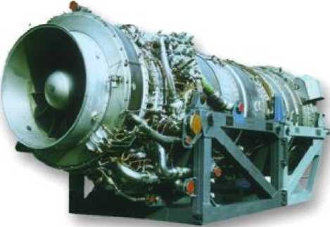
Fig. 1. Gas turbine engine NK-16ST
Рис. 1. Газотурбинный двигатель НК-16СТ
The engine parameters are listed in table 1.
Table 1
Main parameters of GTE NK-16ST
|
Parameter name |
Value |
|
Power, MW |
16 |
|
Net efficiency, % |
29 |
|
Pressure ratio |
8.85 |
|
Fuel gas consumption, kg / hour |
4240 |
|
Working fluid consumption, kg / sec. |
98 |
|
Gas temperature in front of the turbine, K |
1100 |
|
Power turbine rotation frequency, rpm |
5300 |
|
Temperature of gases at the outlet of the ST, °C |
450 |
Technical solutions that make it possible to implement single-zone diffusion combustion which is most acceptable for ensuring the combustion of gases of various compositions [4] are incorporated in the serial combustion chamber of the NK-16ST engine.
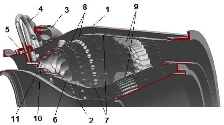
Fig. 2. Combustion chamber of GTU NK-16ST
Рис. 2. Камера сгорания ГТУ НК-16СТ
The combustion chamber (Fig. 2.) consists of an outer 1 and an inner 2 housing, a gas collector 3, pipelines 4 for supplying fuel to the nozzles 5, a flame tube 6 containing casings 7 with holes 8 and mixer nozzles 9. Flame tube head 10 contains 32 burners 11. The flame tube is circular, multi-section, providing convective-film cooling of the walls [5].
Determination of thermophysical characteristics of gaseous fuel. To perform the first part of the calculations the composition of the methane-hydrogen mixture serving as fuel is considered. Its net calorific value is calculated and the stoichiometric coefficient is determined. The composition of the methane-hydrogen mixture adopted for the calculation is given in table 2.
Table 2
C i =
U
0,02404
Composition of methane-hydrogen mixture
|
Component |
Molar mass M i , kg / mol |
Net calorific value Hu, MJ / kg |
Volume fraction v i , % |
|
Ethane C 2 H 6 |
0.0301 |
47.5 |
0.016 |
|
Hydrogen H 2 |
0.002016 |
119.83 |
0.299 |
|
Methane CH 4 |
0.016042 |
50 |
0.685 |
The calculation of the molar concentration of each component is carried out according to the formula:
where C is molar concentration of the i- th component, mol / m 3 ; и is the volume fraction of the i -th component; 0,02404 m3/mol = 0,0224 m3/mol (293,15 К/273,15 К) is molar volume of ideal gas at 20 ˚С (293,15 K) and pressure 101325 Pa, where 0,0224 m3/mol is molar volume of ideal gas at 0 ˚С and pressure 101325 Pa.
Knowing the molar concentration C and molar mass M (Table 2) of each component, we determine the mass concentration of each component contained in 1 m3 of methane-hydrogen mixture Υ , kg / m3 [6]
Υi = CiMi where Υ is the mass concentration of the i-th component in 1 m3 of coke oven gas, kg / m3.
The sum of the components masses contained in 1 m3 of methane-hydrogen mixture will be the mass of 1 m3 of methane-hydrogen mixture, i.e. its density will correspond to:
ρ = ∑ ρ i =0,43kg/m3
i where ρ is the density of the methane-hydrogen mixture, kg / m3.
We determine the mass fraction of each component:
ωi = ρi , ρ where ω is the mass fraction of the i-th component.
The results of calculating the mass fractions of the components are shown in table 3.
Table 3
Mass fractions of the components
|
Component |
Component mass in 1 m3 р i , kg / m3 |
Mass fraction ω i |
|
Ethane C 2 H 6 |
0,020 |
0,039 |
|
Hydrogen H 2 |
0,025 |
0,049 |
|
Methane CH 4 |
0,457 |
0,910 |
As the mass fractions of the components are known, we can calculate the mass calorific value. For the composition under consideration, the net calorific value of the methane-hydrogen mixture H uMH , MJ / kg is:
H uMH = ∑ ω i H u i =53,38 MJ / kg =53,38 (5)
i where H is the net calorific value of the i-th component, MJ / kg (Table 2).
The stoichiometric coefficient of the methane-hydrogen mixture L 0 , kg of air / kg of fuel, is the mass of air required for complete combustion of 1 kg of the methane-hydrogen mixture. For this, it is necessary to estimate the amount of oxygen required for the combustion of all combustible components of the methane-hydrogen mixture, i.e., hydrogen H 2 , methane CH 4 , ethane C 2 H 6 .
It is known that 1 kg of C 2 H 6 reacts stoichiometrically with 3.73 kg O 2 , 1 kg of H 2 - with 7.9 kg of O 2 , 1 kg of CH 4 - with 3.99 kg of O 2 . Thus, the amount of oxygen m required for the combustion of 1 kg of methane-hydrogen mixture is:
m 0 = ∑ ω i m 0 i =4,17kg, (6)
i where m is the mass of oxygen, stoichiometrically reacting with the i-th component, kg.
Taking into account that 1 kg of air contains 0.232 kg of oxygen, we get the stoichiometric coefficient:
l = m0«_ = 17,99 kg ar
0 0,232 kg fuel
When the NK-16ST engine is operating at the nominal mode ( N ST = 16 MW) natural gas consumption is G NG = 1.179 kg / s (see Table 1). The equivalent consumption of the methane-hydrogen gas mixture G MH for the same mode will be:
NG u NG G MH - .. -----= Ukg/ s ,
HuMH where HuMH = 49.84 MJ / kg is the net calorific value of natural gas.
When the fuel gas consumption is known, it is necessary to perform the second part of the calculation and determine whether the fuel system can pass this consumption through itself, that is, whether the condition is met:
G F = G c (9)
where G F is the fuel consumption at the outlet of the gas meter, G c is the consumption through the fuel system of the combustion chamber.
Calculation of the fuel system . The combustion chamber fuel system refers to the fuel manifold, fuel lines and nozzles (fig. 2).
The flow rate through the fuel system of the combustion chamber is determined by the formula [7]: G c - PF n J2P(Pi n - P c ) (10)
where μ is the coefficient of consumption of the combustion chamber fuel system; F n is the total area of the nozzle openings; ρ is the density of the fuel gas; p in is the static pressure of the fuel gas at the inlet to the fuel manifold; p c is static air pressure in the combustion chamber.
The density of the fuel gas is determined by the formula:
P -
pin
RT G where RG is the gas constant of the fuel gas; T is the temperature. Substituting the expression for the density in (10), we obtain:
. G c - pF 2 p^ ( P n - P c ) (11)
RGT
T
Substituting (11) into (9) and multiplying both sides of the equality by and carrying out the
pin necessary transformations, we obtain:
or
GF T
pin
- pF
R
GF T
pc p
- pF
( 1 A
-1
NRg I pJ
where p - p n- . pc
GT GT
The parameters F and c will be called the consumption characteristics of the engine fuel pin
pin
system and the combustion chamber fuel system, respectively.
Let us define graphically the value of the parameter p for the nominal operating mode of the NK-
16ST engine on natural gas (Fig. 3). To do this, we will build curves
G F T
and
pc p
GF T pin
= ^F
2 ( 1'
R
for different values p and find the point of their intersection. When
constructing the curves, we consider G F = G NG = 1.179 kg/s, T = 293 K, p c = 941438.4 Pa (from the throttle characteristic of the NK-16ST engine), R G = 519 J/(kg ∙ K), µ = 0.731 (by the results of blowing the fuel system of the combustion chamber), F n = 0.000845 m2 (the combustion chamber NK-16ST has 32 nozzles; each of them has 4 holes with a diameter of d hol = 2.9 mm). From Fig. 3 it can be seen that the curves of the consumption characteristics intersect at the point p = 1.25, which corresponds to the pressure at the inlet to the fuel system of the combustion chamber p in = 1.25 ∙ 941438.4 Pa = 1176798 Pa = 12 kgf / cm2.
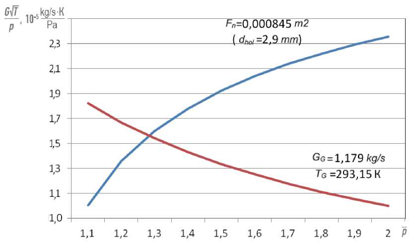
Fig. 3. Consumption characteristics of the engine fuel system and the combustion chamber fuel system when the engine is running on natural gas
Рис. 3. Расходные характеристики топливной системы двигателя и топливной системы камеры сгорания при работе двигателя на природном газе
The graphs (Fig. 4) show the curves of the consumption characteristics of the engine fuel system and the combustion chamber fuel system, built for the operation of the NK-16ST engine on methanehydrogen mixture. When plotting the curves, GF = GMH = 1.1 kg / s, RG = 688 J / (kg ∙ K). The figure shows that when using nozzles with standard hole diameters dhol = 2.9 mm (Fn= 0.000845 m2), the consumption characteristics curves intersect at point p = 1.25, which corresponds to the pressure at the inlet to the combustion chamber fuel system pin = 1. 25 ∙ 941438.4 Pa = 1181505 Pa = 12.05 kgf / cm2. In order for the curves of the consumption characteristics to intersect at the point p = 1.28 (as when the engine is running on natural gas), it is necessary to increase the diameter of the nozzle openings to dhol = 3
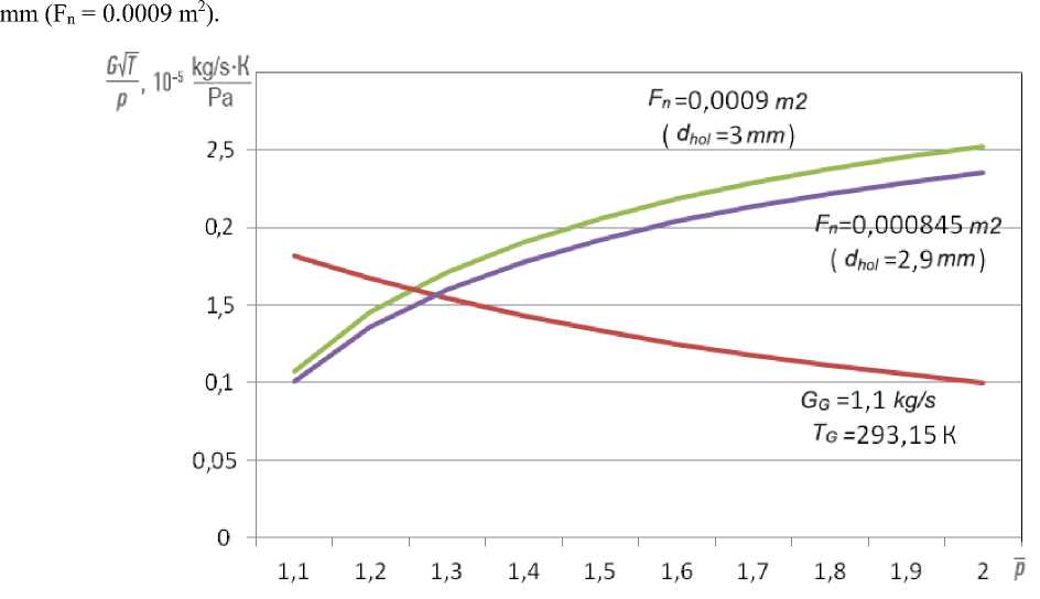
Fig. 4. Consumption characteristics of the fuel system of the combustion chamber system when the engine is running on a methane-hydrogen mixture
Рис. 4. Расходные характеристики топливной системы двигателя и топливной системы камеры сгорания при работе двигателя на метано-водородной смеси
The following recommendations were developed for the improvement of the fuel system for operation on a methane-hydrogen mixture in accordance with the performed calculation: 1) the diameter of the gas supply pipelines to the nozzles should be changed; 2) the internal channels of the nozzle and the diameters of the holes for the jet gas supply should be increased.
Combustion chamber calculation. In the third part, the necessity to redistribute the air supply holes along the length of the flame tube is calculated.
The swirling jets of the fuel-air mixture leaving the burners interact with the air supplied from the main holes to the combustion and mixing zone [8] in the flame tube of the combustion chamber (see Fig. 2).
The depth of penetration of air jets in the holes located in the combustion zone is determined by their diameter and the ratio of the gas-dynamic pressures of the air jets and the gas flow. "Secondary" air supplied to the mixing zone of the combustion chamber through the inlet mixing pipes determines the maximum temperature and affects the formation of the temperature field of the gas flow at the outlet of the combustion chamber [9] (see Fig. 2).
Some assumptions must be made to calculate the air distribution along the length of the flame tube:
-
1. The number of air supply belts corresponds to the value of the serial combustion chamber (Table 4).
-
1. The relative area of the holes in each belt is determined (Fig. 5.)
-
2. Relative distances L i = L i / L FT , where L i is the distance from the flame tube head to the center of the holes or the middle of the mixing pipes, L is the length of the flame tube.
-
3. Neglecting the difference in the respective coefficients of the flow rate of the holes, we assume that the indicated relative areas of the holes will be equal to the corresponding relative values of the flow rate of air through them. Thus, the air flow rate along the belts of the combustion chamber is distributed in proportion to the total areas of the passage sections of the holes and slots through the belts [10].
-
4. Air consumption in the i-th section is determined by the formula:
F fi = i (13)
F0
where F is the total area of the holes in the i -th belt, F is the total area of all holes.
gi = fi
The check of the adopted air distribution is the fulfillment of the condition:
Z gi= 1 (15)
G i = g i • G a (16)
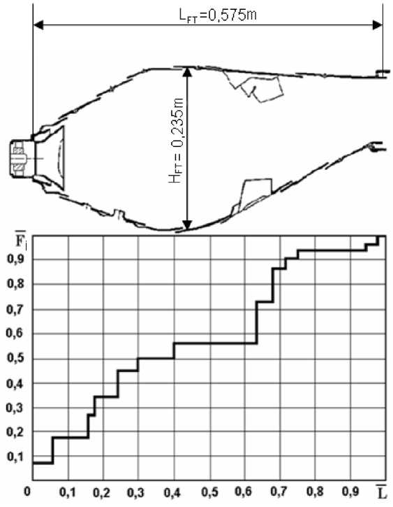
Fig. 5. Air distribution along the length of the flame tube
Рис. 5. Распределение воздуха по длине жаровой трубы
The graph (see Fig. 5) shows that 70% of the air is involved in the organization of combustion processes, and 30% of the air entering the combustion chamber is spent on cooling the flame tube. In this connection, it can be argued that the cooling system is acceptable to ensure the required state of the walls during combustion of a methane-hydrogen mixture and does not need additional revision [11].
By calculating the air flow rate in the estimated zone, one can determine the excess air ratio in this area of the flame tube:
a =
G a
L о • G f
where L 0 is the stoichiometric coefficient for the fuel under consideration.
If we take into account that the total area of the flame tube opening is F 0 = 164474 mm2, and the air flow rate at 16 MW mode G a = 98 kg / s (see Table 1) and consider three belts in the flame tube participating in the combustion process (flame tube head and two air supply belts), then in these belts it is possible to determine the parameters discussed above [12; 13].
Table 4
Parameters in the design sections of the flame tube
|
Flame tube head |
Outer casing of the flame tube (belts of holes) |
Inner casing of the flame tube (belts of holes) |
||
|
I O |
II O |
I IN |
II IN |
|
|
Hole area F i , mm2 |
||||
|
12829 |
9286,55 |
12363,75 |
6649 |
6181,9 |
|
relative hole area |
||||
|
0,0780 |
0,0564 |
0,0752 |
0,0404 |
0,0375 |
|
air flow rate in the section, kg/s |
||||
|
7,644 |
5,527 |
7,370 |
3,959 |
3,675 |
|
α excess air ratio |
||||
|
Use of natural gas as fuel |
||||
|
0,387 |
0,279 |
0,372 |
0,200 |
0,186 |
|
Total excess air ratio for the combustion zone |
||||
|
1,424 |
||||
|
Use of methane-hydrogen mixture as fuel |
||||
|
0,386 |
0,279 |
0,372 |
0,199 |
0,185 |
|
Total excess air ratio for the combustion zone |
||||
|
1,421 |
||||
From table 4 it can be seen that the excess air ratios at the burners’ outlet as well as in the combustion zone of the combustion chamber operating on natural gas and methane-hydrogen mixture are close in their values. This is due to the fact that the stoichiometric coefficient of the methane-hydrogen mixture is higher, while combustion occurs at a lower consumption of the methane-hydrogen mixture.
To determine the gas temperature in the combustion zone, the following expression can be used according to the data obtained [14]:
T * T* Hu • n
tg = Tw + ~at nc.z> 1,0. CPg (1 + a • L0 )
where с р G is the average gas heat capacity at constant pressure; Hu is the net calorific value; η is
*
completeness of combustion; α is the excess air ratio in the calculated area; Tw is the temperature in front of the swirler, K.
According to the results of the calculation, the temperature in the combustion zone when burning a methane-hydrogen mixture in the combustion chamber is T b = 2314.5 K, and when burning natural gas, T b = 2213.06 K, which are close values.
To assess the sufficiency of the flame tube volume for combustion of a given flow rate of the fuel-air mixture, the volumetric heat density parameter is used [15]:
Q = Ga • Hu • nG
v a • L 0 • Vft • P * c
For a serial combustion chamber operating on natural gas, Q v is 3.12 • 106 J / h • m3 Pa, and for one working on a methane-hydrogen mixture Q v is 3.14 • 106 J / h • m3 Pa. Whence it can be seen that this parameter is within the range recommended for modern GTE combustion chambers: Q v = (1.2 ^ 6.5) • 10 6 J / h • m3 Pa, and has a guaranteed margin. In this connection, the flame tube volume is sufficient for combustion of the gas of the considered composition. The data obtained indicate that changes in the flame tube volume and redistribution of holes in it are not required.
Conclusion.
-
1. The calculation of the fuel system and the combustion chamber for the GTU adaptation to operation on gases different in composition from natural gas has been performed.
-
2. The calculation confirmed the possibility of operation of the gas turbine unit NK-16ST on a methane-hydrogen mixture.
-
3. To supply large volumes of methane-hydrogen mixture, in comparison with natural gas, it may be necessary to modify the fuel system in terms of increasing the size of the fuel pipelines, changing the dosing units, regulating and increasing the diameter of the holes in the fuel nozzles.
-
4. Changes in the flame tube volume and redistribution of air flow along its length are not required.
References The possibility of using methane-hydrogen fuel in converted gas turbine engines for power plants
- Aksyutin O. E., Ishkov A. G., Romanov K. V., Teterevlev R. V., Pystina E. A. [Contribution of the gas industry to the formation of a hydrogen-based energy model]. Vesti gazovoy nauki. 2017, No. 5 (33), P. 12–20. (In Russ.)
- Sadiki A., Repp S., Schneider C., Dreizler A., Janicka J. Numerical and experimental investigations of confined swirling combusting flows. Progress in Computational Fluid Dynamics, an International Journal. 2003, Vol. 3, No. 2-4, P. 78–88.3.
- Lefebvre A. H. Fuel effects on gas turbine combustion-ignition, stability, and combustion efficiency. Am. Soc. Mech. Eng., (Pap.); (United States). 1984, Vol. 84, No. CONF-840611.
- Gritsenko E. A., Danilchenko V. P., Lukachev S. V. Konvertirovanie aviatsionnykh GTD v gazoturbinnye ustanovki nazemnogo primeneniya [Conversion of aviation gas turbine engines to land-based gas turbines]. Samara, SNTs RAN Publ., 2004, P. 266.
- Baklanov A. V. [Controlling fuel combustion process by burner design change in gas turbine engine combustion chamber]. Vestnik Moskovskogo aviatsionnogo instituta. 2018, Vol. 25, No. 2, P. 73–85. (In Russ.)
- Baklanov A. V., Neumoin S. P., Markushin A. N. [Assessment of possible operating modes of the NK-16ST GTU when using associated petroleum gas as fuel]. Gas industry. 2017, No. 5 (752), P. 80–86. (In Russ.)
- Gritsenko E. A., Danilchenko V. P., Lukachev S. V. et al. Nekotorye voprosy proektirovaniya aviatsionnykh gazoturbinnykh dvigateley [Some issues of designing aircraft gas turbine engines]. Samara, SNTs RAN Publ., 2002, P. 527.
- Markushin A. N., Baklanov A. V. [investigation of the gas turbine engine combustion chamber workflow. Vestnik Samarskogo universiteta]. Aerokosmicheskaya tekhnika, tekhnologii i mashinostroyeniye. 2016, Vol. 15, No. 3, P. 81–89. (In Russ.)
- Lefebvre A. H., Ballal D. R. Gas Turbine Combustion: Alternative Fuelsand Emissions, 3rd ed., CRCPress. 2010. 537 p.
- Baklanov A. V., Neumoin S. P. [Possibility of using coke oven gas in converted gas turbine units of power and compressor stations]. Gas industry. 2019, No. 3 (781), P. 84–91. (In Russ.)
- Danilchenko V. P., Lukachev S. V., Kovylov J. L. [Design of aircraft gas turbine engines]. Samara, SNTs RAN Publ., 2008, P. 260.
- Baklanov A. V. [The impact of the of fuel supplying method to the combustion chamber on carbon oxides formation in combustion products of the gas turbine engine]. Vestnik Moskovskogo aviatsionnogo instituta. 2019, Vol. 26, No. 1, P. 111–125. (In Russ.)
- Moses C., Roets P. Properties, Characteristics and Combustion Performance of Sasol Fully Synthetic Jet Fuel. ASME Journal of Engineering for Gas Turbines and Power. 2009, Vol. 131, No. 4, P. 041502–041502-17.
- Markushin A. N., Baklanov A. V. [Testing stands for researching the processes and maturation of low emission combusters]. Vestnik of the Samara State Aerospace University. 2013, No. 3-1 (41), P. 131–138. (In Russ.)
- Mingazov B. G. Kamery sgoraniya gazoturbinnykh dvigateley [The combustion chamber of gas turbine engines]. Kazan, izd-vo Kazan. gos. tekhn. un-ta Publ., 2004, P. 220.
