The study of the engine-flywheel housing made by additive technology

Author: Ermakov D.V.
Journal: Сибирский аэрокосмический журнал @vestnik-sibsau
Section: Технологические процессы и материалы
Article in issue: 4 т.18, 2017.
Free access
The first commercial equipment for additive technology production with 3D-printing was made more than 30 years ago. In the mid 90-ies 3D-printing was used mainly in research activities. The wide spread of digital technology in the field of design, modeling, calculations and machining stimulated a rapid development of additive technology. To evaluate the application of the parts printed on a 3D-printer, there was conducted a research of the design of the reaction wheels engines. On the basis of the pre-designed 3D-model there were made two housings of powder materials - alloys АК9Ч and AlSi10Mg were constructed. The analysis of the stability of the geometry of the engine housings to thermal effects, susceptibility to mechanical loads in the model layout of the engine-flywheel was conducted. Outgassing in vacuum was defined and the microstructure of additively manufactured materials was researched. Test results proved the possibility of application of the additively manufactured housing made of selected alloys with sufficient mechanical strength in the composition of the engine-flywheel. There is obviously a need to continue the studies on the properties of materials used in additive technologies in order to compile a list of materials with their properties and application characteristics in the design of the engine- flywheel.
Additive technology, post processing, detail, engine-flywheel, mechanical load, outgassing
Short address: https://sciup.org/148177778
IDR: 148177778 | UDC: 531.383
Исследование корпуса двигателя-маховика, изготовленного по аддитивной технологии
Первые коммерческие разработки оборудования, позволяющего изготавливать изделия по аддитивной тех- нологии методами 3D-печати, появились более 30 лет назад. Еще в середине 90-х годов трехмерная печать использовалась главным образом в научно-исследовательской деятельности. Широкое распространение цифровых технологий в области проектирования, моделирования расчетов и механообработки стимулировало взрывной характер развития аддитивной технологии. Для оценки применения деталей, напечатанных на 3D-принтере, в конструкции двигателей-маховиков про- ведена исследовательская работа. По предварительно спроектированной 3D-модели изготовлены два корпуса из порошковых материалов - сплавов АК9Ч и AlSi10Mg. Проведен анализ стойкости геометрии корпусов к температурным воздействиям, восприимчивости к механическим нагрузкам в составе макета двигателя- маховика, определено газовыделение в условиях вакуума, исследована микроструктура аддитивно полученных материалов. По результатам испытаний сделано заключение о возможности применения 3D-корпусов из выбранных сплавов с достаточной механической прочностью в составе прибора. Сделан вывод о необходимости даль- нейшего изучения свойств материалов, применяемых в аддитивной технологии, для составления перечня материалов с указанием их свойств и особенностей применения в конструкции двигателей-маховиков.
Text of the scientific article The study of the engine-flywheel housing made by additive technology
Introduction. The object of the study is an additive spacecrafts. The subject of research is additively manu-technology, used in the manufacture of engine-flywheels factured engine housings made of Russian powder mateparts for the systems of orientation and stabilization of rial AK9Ч and its foreign counterpart AlSi10Mg [1–4].
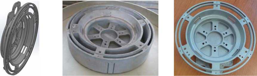
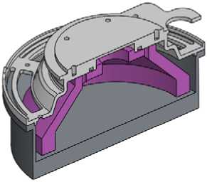
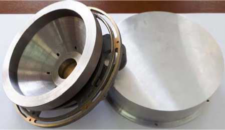
Work description. On the basis of pre-designed 3Dmodel two housings were made on 3-D printer of alloys АК9Ч and AlSi10Mg (fig. 1). Casual housing is made of aluminium rolling brand AMg6 GOST 21488–97.
To evaluate the performance of the studied housings the following program of works was composed:
-
– mechanical processing on accordance to the drawing;
-
– control of dimensions according to the drawing;
-
– check of gassing in accordance with the requirements of the materials used in engine-flywheels, GOST R 50109–92;
-
- the impact of temperature of +60 and -60 ° C;
-
– control dimensional stability on accordance to the drawing;
-
– analysis of the microstructure of the alloys;
-
– testing the mechanical strength of the housing with the installed load, simulating the weight of the electronics and the electric motor.
The results of the tests should show whether the housings possess the sufficient mechanical strength, resistance to temperature changes; the value of outgassing in vacuum also must be determined.
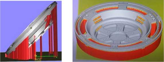
It should be noted that the housings were printed at different angles to the main setting surface adjacent to the spacecraft (fig. 2). This is reflected in the amount of required technological support (the support surface for forming planes that are in suspended state), and subsequently on the post-processing of the case.
Support of the housing of the alloy AlSi10Mg was insignificant; it was removed using the special machining tool (fig. 3) [5; 6]. Then the body was subjected to sandblast treatment, which completed the process of rough post-processing, and then machined using universal equipment to conform to the drawing.
Due to the massive support of the housing from the alloy АК9Ч from the beginning were used the universal machines for removal. This made it possible to combine the removal of the support (fig. 4) and machining of surfaces to meet the requirements of the drawing, which ultimately reduced the production cycle of the housing.
а
b
Fig. 1. 3D model of engine housing ( а ), printed housings made of alloys АК9Ч ( b ) and AlSi10Mg ( c )
Рис. 1. 3D-модель корпуса ( а ), напечатанные корпуса из сплавов АК9Ч ( б ) и AlSi10Mg ( в )
а b
Fig. 2. 3D model of engine housing made of alloys АК9Ч ( a ) and AlSi10Mg ( b ) with the support surface
Рис. 2. 3D-модель корпусов из сплавов AlSi10Mg ( а ) и АК9Ч ( б ) с поддержкой
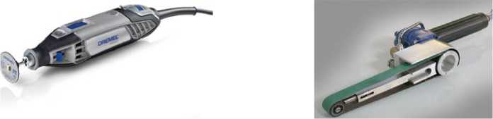
Fig. 3. Special machining tool for removing the support of the housing made of the alloy AlSi10Mg
Рис. 3. Инструмент для удаления поддержки корпуса из сплава AlSi10Mg
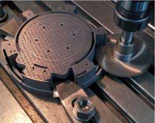
Fig. 4. Housing from the alloy АК9Ч at the stage of support removal
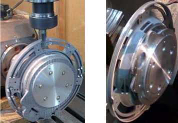
Рис. 4. Корпус из сплава АК9Ч в процессе снятия поддержки
After removing the support and monitoring of the geometry of housings for compliance with the drawing the surfaces not subjected to post-processing were measured. All dimensions meet the drawing, which indicates repeatability of the geometry of engine housings in 3D printing.
Thus, we can conclude: the manufacture of details of precision mechanics by means of additive technologies requires a minimal of finishing post-processing. Therefore, when creating 3D models in CAD, you must set allowances taking into account the subsequent mechanical surface treatment to the required dimensions and choose the optimal variant of the support when printing on a 3D printer [7; 8].
To reduce the impact of increased gassing in vacuum conditions from the materials that are sensitive to the influence of its own external atmosphere, in the design of engines-flywheels must be used the materials that in accordance with GOST R 50109–92 have total mass loss of not more than 1 % and the content of volatile condensable substances is not more than 0.1 %, and the residual outgassing in the vacuum pressure chamber of engineflywheel, where the low pressure is supported.
The residual outgassing in vacuum chamber was defined at the low pressure 1.33∙10–1–1.33∙10–2 Pа (10–3– 10–4 mmHg) and the temperature (80 ± 3) ºС during 48 hours and in accordance with GOST R 50109–92.
The residual outgassing in vacuum chamber is calculated:
ΔР = Рз – Рп, where Рз – is the pressure in a loaded chamber, Pa; Рп – is the pressure in an unloaded chamber, Pa.
Then it comes to the volume V 2 =1 l using the formula:
Р2 = ΔРV1/ V2 , where Р2 – given volume in the finished item, Pa; V1 – chamber volume, l; V2 – volume of the finished item, l.
The results of outgassing are supplied at tab. 1 and 2.
Table 1
The residual outgassing in vacuum chamber
|
Housing material |
data |
|
АМg6 |
0.25 |
|
АК9Ч |
0.48 |
|
AlSi10Mg |
0.90 |
Housings made by additive technology meet the requirements for outgassing for the materials used in the construction of engines-flywheels of non-hermetic character in the construction of the spacecraft.
Table 2
Outgassing in accordance with GOST R 50109–92
|
Housing material |
Mass loss, % |
Condensing volatiles, % |
|
АМg6 |
0.0 |
0.0 |
|
АК9Ч |
0.0 |
0.0 |
|
AlSi10Mg |
0.0 |
0.0 |
After the control of outgassing the housings were subjected to temperature exposure +60 and -60 ° C (three cycles). The dwell time at each temperature was 2 hours, excluding the time of its setting.
Control of the geometry of the housings after these exposures showed no deviation relative to initial values. Consequently, the housings have sufficient vitality to temperature effects and can be recommended for the usage in the construction of the engines-flywheels of the spacecrafts.
Analysis of the microstructure of the alloys showed that it is mainly a mixture of aluminium and silicon. However, on the photographs of the microstructure the grains of primary aluminum, crystallizing in the first hypoeutectic alloys are not clearly observed [9]. While the silicon inclusions have predominantly spherical shape in comparison with the conventional lamellar cast structure (fig. 5). The hardness of the housings made of alloys system Al–Si has the extremely high value (HB 110 in the initial state and HB 107 after annealing at temperature 320 ºС). Possible reasons for these differences lie in nonequilibrium conditions of crystallization and cooling, which are the feature of additive technologies.
The results of the preliminary calculation. Before the full-scale tests of the layout model of the engineflywheel on a vibration stand the model with the defined parameters of the studied housings with mounted loads, simulating the weight of the electric motor 1 and controlling electronics 2 for mechanical calculation was prepared (fig. 6) [10; 11].
When designing the mathematical model the mechanical properties of the materials of the housings were taken the same as the alloys AlSi10Mg and AK9Ч are interchangeable.
As the joints of details was selected the global contact, in the result while constructing the final elemental model we obtained a joint mesh (fig. 7) [12; 13]. Mount housing set by the parameter “fixed geometry” for main setting surface.
The results of a modal analysis of the housings confirmed the absence of resonant frequencies below 100 Hz, which meets the general requirements for the design of engine-flywheels. The first resonant frequency of the model is 476.64 Hz.
Analysis of the response of housings to random broadband vibration (RBV) conducted to determine their resistance to external influence and identify areas of maximum stress concentration. The study was performed along three mutually perpendicular axes: in the direction perpendicular to the setting plane (along axis OZ) and in directions parallel to it (along the axes OX and OY).
The loads were selected from the condition of passing the preliminary and qualification of the engine-flywheels.
For comparison, tab. 3 shows the safety factors of the housings made of AK9Ч and AlSi10Mg alloys and a standard housing of AMg6 alloy.
The results of full-scale tests. After performing the preliminary calculations of the layout model we produced simulators of the electric motors and service electronics (fig. 8) for installation on a 3D body.
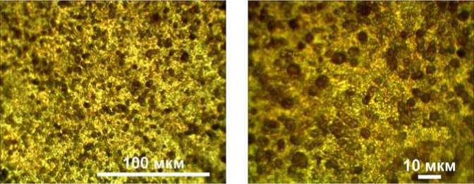
Fig. 5. Microstructure of alloys system Al–Si made by 3D-printing
Рис. 5. Микроструктура сплавов системы Al–Si, полученных 3D-печатью
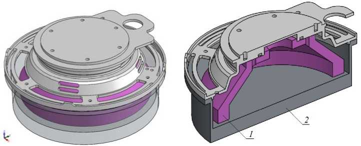
Fig. 6. Analyzed 3D-model
Рис. 6. Расчетная 3D-модель
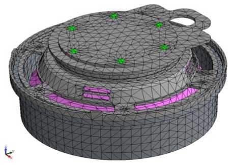
Fig. 7. Finite-element 3D-model
Рис. 7. Конечно-элементная 3D-модель
Table 3
|
The mean quadratic value of acceleration, g |
The direction of action |
Material |
The reserve coefficient K з |
|
|
on yield stress |
on strength limit |
|||
|
17 |
along axis OZ |
АК9Ч/ AlSi10Mg |
1.27 |
1.25 |
|
AMg6 |
2.49 |
3.32 |
||
|
along axis OX |
АК9Ч/ AlSi10Mg |
1.01 |
0.99 |
|
|
AMг6 |
2.0 |
2.68 |
||
|
along axis OY |
АК9Ч/ AlSi10Mg |
0.99 |
0.97 |
|
|
AMg6 |
1.98 |
2.64 |
||
|
12 |
along axis OZ |
АК9Ч/ AlSi10Mg |
1.89 |
1.85 |
|
AMg6 |
3.51 |
4.7 |
||
|
along axis OX |
АК9Ч/ AlSi10Mg |
1.58 |
1.55 |
|
|
AMг6 |
3.12 |
4.15 |
||
|
along axis OY |
АК9Ч/ AlSi10Mg |
1.4 |
1.37 |
|
|
AMg6 |
3.03 |
4.04 |
||
The calculated values of the safety factors
а
b
Fig. 8. 3D-model ( а ) and layout model for mechanical testing ( b )
Рис. 8. 3D-модель ( а ) и макет для механических испытаний ( б )
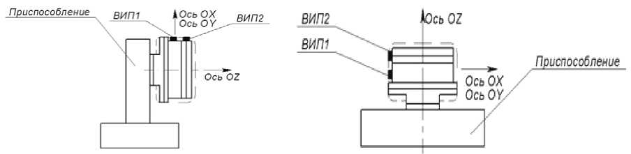
Fig. 9. The scheme of installed on the layout sensors
Рис. 9. Схема установки датчиков на макете
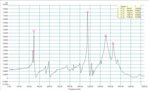
Fig. 10. Search results of resonances along the axis ОX before the vibration effect ( а ); after the vibration effect ( b )
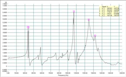
b
Рис. 10. Результаты поиска резонансов вдоль оси ОX до воздействия вибрации ( а ); после воздействия ( б )
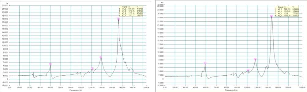
а
b
Fig. 11. Search results of resonances along the axis ОY before the vibration effect ( а ); after the vibration effect ( b )
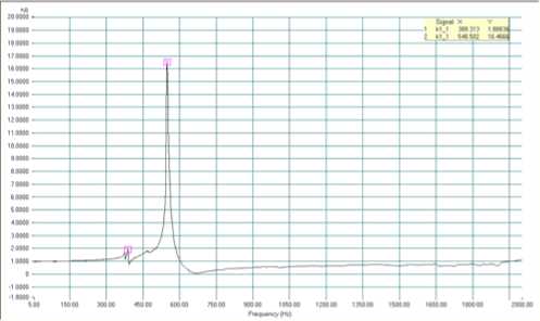
Fig. 12. Search results of resonances along the axis ОZ before the vibration effect ( а ); after the vibration effect ( b )
Рис. 11. Результаты поиска резонансов вдоль оси ОY до воздействия вибрации ( а ); после воздействия ( б )
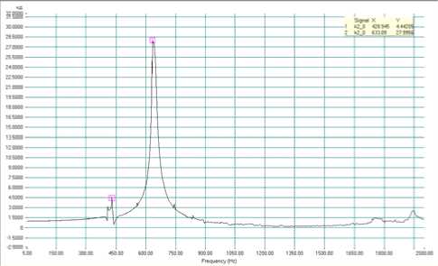
b
Рис. 12. Результаты поиска резонансов вдоль оси ОZ до воздействия вибрации ( а ); после воздействия ( б )
а
b
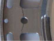
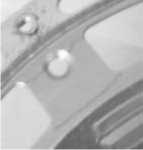
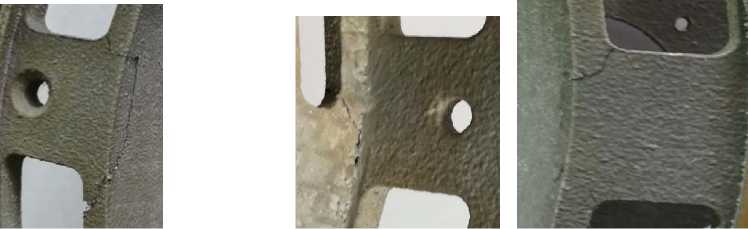
Fig. 13. Damages of housings made of AK9Ч ( а ) and AlSi10Mg alloys ( b )
Рис. 13. Повреждения корпусов из сплавов АК9Ч ( а ) и AlSi10Mg ( б )
The full-scale tests on the response of housings to random broadband vibration (RBV) were carried out in two stages according to the requirements for acceptance and qualification testing.
The tests were carried out alternately in each of three mutually perpendicular directions with the installed on the model sensors (fig. 9) in the following order [14; 15]:
-
– search for resonant frequencies of structural elements;
-
– loading of random broadband vibration (RBV);
-
– search for resonant frequencies of structural elements.
The results of full-scale tests on the axes of the model at the stage of preliminary tests are presented on graphs (fig. 10–12).
The full-scale tests on the response of housings to random broadband vibration (RBV) during the qualification tests confirmed the results of the preliminary mechanical analysis of the mathematical model: housings made of AK9Ч and AlSi10Mg alloys are unstable to the selected load values, and will deform in the most loaded areas (fig. 13).
The check of the full-scale model on a vibration stand not only showed the adequacy of the preliminary analysis of a mathematical model but also proved the correctness of the choice of properties of additively manufactured materials that is proved by the nature of the deformation on the housings.
Conclusion. The porosity between the printed layers is higher than in one layer of rolling. This should be considered when choosing the location of the workpiece in the print chamber. The content of pores is less than 1 % in the transverse and longitudinal directions and the pores are about the same size and geometry, which demonstrates the high quality of the sintering.
Housings made of AK9Ч and AlSi10Mg alloys by means of additive technology can be recommended for use in the construction of the engine-flywheels of unpressurized form while reducing the demands of the susceptibility of the structure to mechanical loads.
However, having chosen an alloy that meets the requirements for materials used in the design of the engineflywheels; it is possible to use additive technology for manufacturing the parts without the reduction of these requirements. So, when adding titanium carbide in the alloys of the studied housings, the reserve coefficient is increased in 1.5–2 times.
Thus, the samples obtained by laser sintering can be used for the manufacture of parts while maintaining properties similar to the properties of their prototypes, made by means of traditional technology.
There is obviously a need to continue the studies on the properties of materials used in additive technologies in order to compile a list of materials with their properties and application characteristics in the design of the engine-flywheel construction.
References The study of the engine-flywheel housing made by additive technology
- Официальный сайт компании Boeing . URL: http://www.boeing.com/features/2016/08/record-books-08-16.page (дата обращения: 06.10.16).
- Официальный сайт компании SpaseX . URL: http://www.spacex.com/news/2014/07/31/spacex-launches-3Dprinted-part-space-creates-printed-engine-chamber-crewed (дата обращения: 06.10.16).
- Балякин А. В., Смелов В. Г., Чемпинский Л. А. Применение аддитивных технологий для создания деталей камеры сгорания//Вестник Самар. гос. аэрокосмич. ун-та. 2012. № 3 (34). С. 458.
- Ученые Самарского университета впервые «напечатали» на 3D-принтере камеру сгорания газотурбинного двигателя: офиц. сайт НИ СГАУ . URL: http://www.ssau.ru/news/12978-Uchenye-Samarskogo-universiteta-vpervye-napechatali-na-3Dprintere-kameru-sgoraniya-gazoturbinnogo-dvigatelya/(дата обращения: 06.10.16).
- Лысыч М. Н., Шабанов М. Л., Романов В. В. Области применения технологий 3D-печати//Современные наукоемкие технологии. 2014. № 12. С. 345.
- Токарев Б. Е., Токарев Р. Б. Анализ технологий рынка 3D-печати: два года спустя//Науковедение: интернет-журнал. 2016. Т. 8, № 1. DOI: 10.15862/28EVN116 (дата обращения: 06.10.16).
- Меркин Д. Р. Гироскопические системы. М.: Физматгиз: Наука, 1974. 356 с.
- Ишлинский А. Ю. Механика гироскопических систем. М.: Изд-во АН СССР, 1963. 327 с.
- Тищенко О. Ф. Элементы приборных устройств. М.: Высш. шк., 1978. 384 с.
- Афанасьев В. А. Экспериментальная отработка летательных аппаратов. М.: МАИ, 1994. 345 с.
- Егоров Ю. П., Лозинский Ю. М., Хворова И. А. Материаловедение: учеб. пособие. 3-е изд. Томск: Изд-во Том. политехн. ун-та, 2009. 219 с.
- Первицкий Ю. Д. Расчет и конструирование точных механизмов. М.: Высш. шк., 1976. 456 с.
- Биргер И. А., Шорр Б. А., Иосилевич Г. Б. Расчет на прочность деталей машин: справочник. 3-е изд., перераб. и доп. М.: Машиностроение, 1979. 702 с.
- Исаакович М. М., Клейман Л. И., Перчанок Б. Х. Устранение вибрации электрических машин. Л.: Энергия. Ленингр. отд-ние, 1979. 200 с.
- Шубов И. Г. Шум и вибрация электрических машин. Л.: Энергия, 1973. 259 с.
