The surface roughness during electro-contact-electrochemical machining with vibration of a cathode-tool

Author: Shestakov I.Ya., Semenova L.A., Shestakov V.I., Shvaleva N.A., Remizov I.A.
Journal: Siberian Aerospace Journal @vestnik-sibsau-en
Section: Technological processes and material science
Article in issue: 4 vol.25, 2024.
Free access
Electrical discharge machining and electrochemical machining of metals are used in the production of parts for aircraft and rocket technology, especially electrical discharge machining. A type of electrical discharge machining, electrical contact machining, is used in metallurgy. The paper investigates a combined method of metal machining, including electrical contact and electrochemical methods using vibration of the electrode tool. This method is used for copying and piercing operations in the manufacture of parts from metals that are difficult to machine mechanically. The peculiarity of the above-mentioned method of electrical machining is the formation of surface roughness of the metal being machined due to anodic dissolution and the electrical discharge machining process. The side surface of the workpiece is formed due to electrochemical processes. The end surface is formed due to electrical contact machining. Based on literature data for pulsed electrochemical machining and experiments, expressions for calculating the roughness parameter of the side surface are obtained. The formula takes into account the time of anodic dissolution for one period of oscillation of the cathode tool, the voltage on the electrodes and the concentration of the electrolyte. The calculation of the roughness parameter of the end surface is carried out similarly to the expression for electrical discharge machining, but instead of the duration of the electric pulse, the duration of contact of the electrodes is used. The experiments carried out confirmed the correctness of the expressions used and made it possible to obtain the dependence of the coefficient on the vibration frequency of the cathode-tool.
Electro-contact-electrochemical method, vibration, electrolyte, side surface, end surface, surface roughness
Short address: https://sciup.org/148329765
IDR: 148329765 | UDC: 621.9.048 | DOI: 10.31772/2712-8970-2024-25-4-539-549
Text of the scientific article The surface roughness during electro-contact-electrochemical machining with vibration of a cathode-tool
The development of modern technology is associated with the use of metals and alloys that are difficult to process mechanically, therefore, electrical processing methods, including combined ones, are increasingly being used [1]. Currently, many combined methods of electrical processing are known. An overview of these methods is presented in [1; 2]. The greatest attention of researchers was attracted by the electroerosion-chemicalm machining (EECM) of metals, as evidenced by numerous publications in collections of scientific papers and conference materials [3-8]. A distinctive feature of this treatment method is the implementation of electrochemical machining (ECM) in a flowing electrolyte in the arcing mode, passing into an arc discharge, and maintaining the interelectrode gap (IEG) constant. In the study of the EECM of the hole stitching, vibration of the tool electrode-tool (ET) was used to intensify the removal of processing products from the interelectrode gap [9; 10]. When the feed rate of the ET is greater than the removal rate of the metal, contact occurs with the workpiece. With a short-term touch, an arc lights up, which leads to erosive removal of the processed metal. The authors of the above-mentioned work called this method the electro-contactelectrochemical method of machining metals (ECECM).
The paper presents the dependence of the firmware speed on the depth of the hole and the vibration frequency of the electrode-tool and does not mention the quality of the resulting surface. No publications have been found on this method.
Surface roughness is an important indicator of the quality of parts, affecting many operational and technical characteristics of machines and devices (Table 1).
Surface roughness affects the processes of friction and wear, impact strength, vibration activity, flowability by liquids and gases, tightness of joints, electrical contact resistance, reflection of electromagnetic waves from the surface, thermal conductivity and radiation properties, strength and quality of coatings.
Table 1
The main technological factors determining operational characteristics of instrument and machine parts
|
Operational characteristics of the details |
Microgeometry (roughness) |
Machining tracks direction |
Hardening |
Microhardness |
Macrogeometry |
|
Fatigue strength (endurance) |
+ |
+ |
+ |
+ |
|
|
Wear resistance |
+ |
+ |
+ |
+ |
+ |
|
Strength of the press joints |
+ |
+ |
+ |
+ |
+ |
|
Stability of landings |
+ |
+ |
+ |
+ |
+ |
|
Corrosion resistance |
+ |
+ |
|||
|
Erosion resistance |
+ |
+ |
|||
|
Heat transfer |
+ |
+ |
|||
|
Moment of friction |
+ |
+ |
+ |
+ |
+ |
It follows from the above that surface roughness affects many operational and technical characteristics of machine parts and devices.
The purpose of the work is to identify the analytical dependence of the surface roughness quality indicator on the processing parameters. In the branch research laboratory at the Siberian State Aerospace University named after Academician M. F. Reshetnev the work on the ECECM is continued. The influence of the frequency and amplitude of vibration of the ET on its wear and processing performance is investigated, and phenomena occurring in the interelectrode gap, varying from zero to the range of vibrations of the ET, are revealed. Based on the research materials, articles have been published and a patent for the ECECM method has been obtained [11].
Materials and research methods
ECECM is a combined method consisting of electrochemical and electrocontact machining. Electrocontact machining is a type of electroerosion machining (EEM). The processes in the electric discharge channel affect the metal removal rate, surface roughness, machining accuracy, durability of the ET, structural changes in the ET, the workpiece and the working fluid.
The surface roughness in the EEM of steels is Ra 0.3–0.6 microns at the direct polarity in the electric spark mode, with the electric pulse mode Rz 20-40 microns [11]. Moreover, the parameter Rz is determined by the pulse energy:
R z = kAP , (1)
where k is a coefficient depending on the processing mode, the material of the ET, the size, type and condition of the working medium. For steels k = 2 ...12 in finishing conditions; k = 10...50 for roughing; p is the exponent of the degree characterizing the shape of the hole, p = 0.3... 0.04; A is the pulse energy, determined by the product of the average values of current and voltage per pulse duration, J.
In [17], it is proposed to use the following dependence to calculate the roughness parameter Rz during EEM:
R z = kA x т И , (2)
where τ and are the pulse duration; x , y are exponents.
The values of the degree indices have been experimentally established for processing nickel-based alloys and for steel 12X18H9T.
The introduction of pulse duration in expression (2) showed that the pulse energy has the greatest effect on roughness.
In combined EECM, the surface roughness mainly depends on the energy of the current pulses causing the electroerosion destruction of the material, and is determined by the expression [18]:
R z = KA13,
where K is a coefficient depending on the metal being processed and for carbon steels K = 0.12 mm/J.
The pulse energy is proposed to be determined by the formula
A =
UI f (1 + a),
where U is the arc gorenje voltage; I is the operating current; f is the pulse repetition rate; a is the coefficient equal to the ratio of the average current density due to the process of electroerosion to the average current density due to the process of anodic dissolution, usually a = 0.1 ... 1.2. At EECM a = 1.2...2.0, at ECECM the frequency f is equal to the frequency of oscillations of the ET.
During the electrochemical treatment of titanium and its alloys in the pulsed mode [19], an empirical dependence of the roughness parameter R a on the process modes was obtained:
R = U - 1,54 t1 ’ 41
R a U т и
T 1,54 c -0,21
where U is the voltage at the electrodes; τи is the duration of the current pulse; T is the period of the current pulse; c is the concentration of the electrolyte.
During ECECM, a constant voltage is used, so the anodic dissolution of the side surface of the workpiece occurs continuously, excluding the moment when the electrodes touch, since at this time the voltage between the electrodes is close to zero. Taking into account this and experimental data, expression (5) will take the form
R = kU °,5 y c -0,5, a
T a where k = 0.1 V- цт, a constant multiplier; U is the average voltage across the electrodes; ty is the time to establish a stable value of surface roughness, in most cases ty = 8 ...10 s; t a is the time of anode dissolution during one period of oscillation of the cathode tool.
The formation of surface roughness occurs due to two processes: electrical erosion and anodic dissolution.
The surface roughness of the R z surface formed by the end of the cathode tool can be estimated by the expression
R z = k ( A л + А мех ) P , (7)
where k is the coefficient depending on the processing mode of the material of the workpiece, in the general case k = 2...50; А эл is the electrical energy released in the MEZ, J; А мех is the mechanical energy of the oscillating mass, J; p is the exponent, p = 0.3...0.04.
Electrical energy is determined by the formula
A л = UI Т э , (8)
where U is the average voltage during processing, V; I is the average value of the current strength during processing, amp; τ э is the time of erosion failure during one period of oscillation of the cathode tool, sec.
Mechanical energy is defined by the expression
А мех = mf2 A 2 , (9)
where m is the mass of the ET, kg; f is the frequency of vibrations of the ET, Hz; And A is the amplitude of vibrations of the ET, m.
It follows from expression (7) that the roughness of the surface formed under the end of the ET is determined by mechanical and erosive action, the so-called electromechanical smoothing, which contributes to obtaining high surface quality (Ra 0.1 microns or less). By changing the oscillation frequency, the ratio of the duration of erosive and electrochemical effects changes. This allows you to change the surface roughness of the workpiece.
Results and discussion
The experiments were carried out on an electric treatment plant based on an edectrodynamic drive [20]. The general view of the installation and the layout of its elements are shown in Fig. 1 and 2.
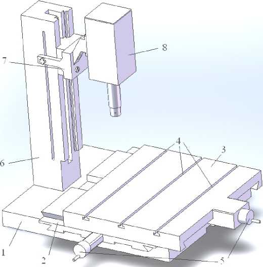
Рис. 1. Внешний вид электроконтактно-химической установки без ванны: 1 - основание; 2 - средняя часть основания; 3 - верхняя часть основания; 4 - пазы;
5 – маховики; 6 – стойка; 7 – держатель; 8 – ЛЭДД
Fig. 1. External appearance of the electrocontact-chemical installation without a bath:
1 – base; 2 – middle part of the base; 3 – upper part of the base; 4 – grooves;
5 – flywheels; 6 – stand; 7 – holder; 8 – LEDM
The developed installation is a desktop version of an electrocontact-chemical machine (Fig. 1). The tub is made of stainless steel sheet and is attached to the table (3) via a dielectric plate.
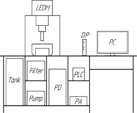
Рис. 2. Компоновка элементов установки электроконтактнохимической обработки:
ЛЭДД – линейный электродинамический двигатель; РМ – распределитель мощности;
ПЛК – программируемый логический контроллер; УМ – усилитель мощности;
ПИ – панель индикации; ПК – персональный компьютер
Fig. 2. Layout of elements of the installation for electrocontact chemical processing: LEDM – linear electrodynamic motor; PD – power distributor; PLC – programmable logic controller; PA – power amplifier; DP – display panel; PC – personal computer
The installation is equipped with a control system for the oscillation frequency of the tool electrode in the range from units to 100 Hz (Fig. 3).
The control system provides a working fluid supply device, which is necessary for automatic filling of the bath with electrolyte. The pump includes a pump, a cartridge filter, a tank, a supply hose and a drain hose. The liquid level is regulated by a float sensor installed inside the working bath.
The entered parameters are recorded by the ADC system, which provides feedback and, through the controller, are sent to the display panel, where the operation of the elements is displayed.
This installation provides a system for recording the movement of the tool electrode using a linear motion sensor.
With this sensor, the processing depth is recorded and analyzed. This sensor is one of the main feedback elements in the system. With its help, the control system varies the output parameters that are necessary for processing the workpiece at this stage. The sensor is powered directly from the controller.
To measure the roughness of the lateral surface, the samples were made separable, i.e. they consisted of two halves. Model 296 profilometers were used to measure the roughness of the side surface, and a MIS–11 double microscope was used for the end surface. An aqueous solution of sodium nitrate with a concentration of 2.5 g/l was used as an electrolyte. During the experiments, the average values of current and voltage were recorded, and waveforms of current, voltage, and interelectrode gap were taken. The oscillograms were used to determine the time of anodic dissolution and the time of erosive destruction of the metal of the workpiece. The hole depth was 10 mm.
The material of the samples is HVG steel. The cathode tool is a tool in the form of a cylindrical copper tube, the outer diameter of which is 7.9 mm; the inner diameter is 5.8 mm, connected to a vibration drive. The electrolyte was supplied to the interelectrode gap through a cathode-tool. The weight of the cathode-tool is 1 kg. The processing parameters are shown in Table 2, the results of calculations and measurements of surface roughness are shown in Table 3.
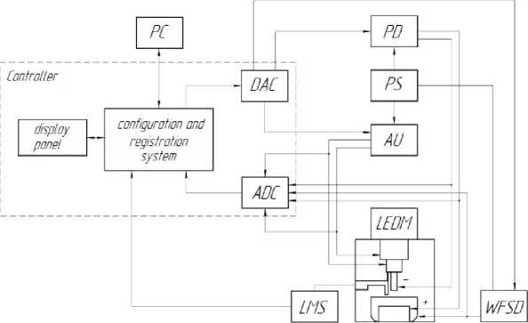
Рис. 3. Блок схема управления установкой ЭКХО:
РМ – распределитель мощности; ИП – источник питания;
УБ – усилительный блок; УПРЖ – устройство подачи рабочей жидкости; РС – персональный компьютер; ДЛП – датчик линейных перемещений; ЛЭДД – линейный электродинамический двигатель; ЦАП – цифровой аналоговый преобразователь; АЦП – аналого-цифровой преобразователь
-
Fig. 3. Block diagram of the control of the ECHO installation: PD – power distributor; PS – power supply;
AU – amplifying unit; WFSD – working fluid supply device; PC – personal computer; LMS – linear motion sensor; LEDM – linear electrodynamic motor; DAC – digital to analog converter; ADC – analog to digital converter
Data analysis of the table. 2 showed that the value of the coefficient k in formula (7) is related to the frequency ratio by the expression:
k i = k 20 f i /20 ,
where ki is the coefficient value at a different oscillation frequency of the cathode-tool, k 20 is the coefficient value at a frequency of 20 Hz, f i is the required value of the oscillation frequency of the cathode–tool.
Machining parameters
Table 2
|
№ pp |
Oscillation frequency, Hz |
average voltage is, V |
average current, amp |
amplitude, mm |
Ratio k (7) |
|
1 |
20 |
11.5 |
10 |
0.8 |
10 |
|
2 |
50 |
11.5 |
11 |
0.7 |
25 |
|
3 |
80 |
11.5 |
12 |
0.6 |
40 |
Table 3
Results of calculations and measurements of surface roughness
|
№ pp |
Estimated value of R a , microns |
Measured value of R a , microns |
||
|
lateral |
the end part |
lateral |
the end part |
|
|
1 |
0.11 |
2.6 |
0.15 |
2.8 |
|
2 |
0.33 |
6.3 |
0.4 |
6.3 |
|
3 |
0.78 |
7.1 |
0.8 |
7.4 |
Conclusion
Changing the oscillation frequency of the cathode tool leads to a change in the roughness of the treated surfaces. By reducing the vibration frequency of the tool, the quality of the treated surface improves, as the time of electrochemical machining increases. The calculated values of the parameters R a practically coincide with the measured ones, which confirms the correctness of the selected formulas, coefficients and exponents.
References The surface roughness during electro-contact-electrochemical machining with vibration of a cathode-tool
- Saushkin B. P. Osnovopolozhniki elektricheskikh metodov i tekhnologii obrabotki materialov [Founders of electrical methods and materials processing technologies]. Moscow, 2020, 226 p.
- Saushkin B. P. [Combined processing methods in mechanical engineering]. Metalloobrabotka. 2003, No. 1, P. 8–17 (In Russ.).
- Smolentsev E. V. Proektirovanie elektricheskikh i kombinirovannykh metodov obrabotki [Design of electrical and combined processing methods]. Moscow, Mechanical Engineering Publ., 2005, 511 p.
- Petrov Yu. N. Elektrokhimicheskaya razmernaya obrabotka metallov [Electrochemical dimensional processing of metals]. Kishinev, 1974, 143 p.
- Razmernaya elektrokhimicheskaya obrabotka detalei mashin: Materialy IV Vsesoyuz. konf. [Dimensional electrochemical processing of machine parts: Materials of the IV All-Union. conf.]. Ed. F. V. Sedykin. Tula, 1975, Vol. 1, 310 p. (In Russ.).
- Smolentsev E. V. [Design of the technological process of electroerosive chemical machining]. Metalloobrabotka. 2008, No. 6, P. 34–39 (In Russ.).
- Boldyrev A. I. [Combined electrochemical-mechanical processing of aerospace equipment parts]. Izvestiya Samarskogo nauchnogo tsentra RAN. 2011. Vol. 13, No. 1(2), P. 293–296 (In Russ.).
- Volkov V. I., Rumyantsev E. M., Nevsky O. I. [Influence of electrolyte composition on the parameters of erosion-electrochemical treatment of the VT3 – 1 alloy]. Tezisy dokl. Vsesoyunoi nauchno-tekhnich. konf. “Kombinirovannye elektroerozionnoelektrokhimicheskie metody razmernoi obrabotki metallov”. [Abstracts of the report of the All-Union scientific and technical conference “Combined electrical discharge and electrochemical methods of dimensional processing of metals”]. Ufa, 1983, P. 7–10 (In Russ.).
- Zaitsev A. N., Zhuravskii A. K., Polyanin V. I. [Features of the mathematical description of the process of electrochemical shaping of the side surface during electroerosive-electrochemical piercing of small holes] Tezisy dokl. Vsesoyuznoi nauchno-tekhn. konf. “Razmernaya eletrokhimicheskaya obrabotka detalei mashin. EKhO-80”. [Abstracts of the report of the All-Union scientific and technical conf. “Dimensional electrochemical processing of machine parts. ECM-80”]. Tula, 1980, P. 371–375 (In Russ.).
- Borodulin V. A., Volkov V. I. [Features of erosion-electrochemical piercing of holes with a depth of more than 10 mm]. Tezisy dokladov Vsesoyuzn. nauch. tekhn. konferentsii. “Kombinirovannye elektroerozionnoelektrokhimicheskie metody razmernoi obrabotki metallov” [Abstracts of reports of the All-Union. scientific tech. conferences “Combined electro-erosionelectrochemical methods of dimensional processing of metals”]. Ufa, 1983, P. 50–53 (In Russ.).
- Shestakov I. Ya. Sposob elektro-kontaktno-erozionno-khimicheskoi obrabotki [Method of electro-contact erosion-chemical processing]. Patent RF, No. 2428287, 2011.
- Shestakov I. Ya., Stryuk A. I., Bezyazykov S. A. [Physical effects and phenomena during electrical processing in a harmonically varying interelectrode gap]. Materialy, tekhnologii, konstruktsii». Krasnoyarsk, 1995, P. 88–92.
- Shestakov I. Ya., Rubanov S. V. [Study of electrical contact processing with vibration of the electrode-tool]. Materialy, tekhnologii, konstruktsii. Krasnoyarsk, 1996, P. 28–32.
- Shestakov I. Ya., Stryuk A. I., Milenin V. N. [Electric contact stitching of rivets]. Perspektivnye materialy, tekhnologii, konstruktsii, ekonomika. 2003, Vol. 9, P. 81–84 (In Russ.).
- Shestakov I. Ya., Stryuk A. I., Tsukanov A. V. [Pulse electrical treatment with a vibrating electrode-tool]. Vestnik SibGAU. 2004, No. 5, P. 253–258 (In Russ.).
- Shestakov I. Ya., Artyukova O. E. [Electrocontact-chemical processing with a vibrating electrode-tool] Мaterialy XIV Mezhdunar. nauch. konf. “Reshetnevskie chteniya” [Materials XIV Intern. Scientific. Conf “Reshetnev reading”]. Krasnoyarsk, 2010, P. 344–346 (In Russ.).
- Dal'skii A. M., Kosilova A. G., Meshcheryakov R. K., Suslov A. G. Spravochnik tekhnologamashinostroitelya: v 2-kh t [Handbook of a mechanical engineer: in 2 volumes]. Moscow, Mashinostroenie-1 Publ., 2003, Vol. 2, 943 p.
- Foteev N. K. Tekhnologiya elektroerozionnoi obrabotki [Electric discharge machining technology]. Moscow, Mashinostroenie Publ., 1980, 184 p.
- Kovalenko V. S. Elektrofizicheskie i elektrokhimicheskie metody obrabotki materialov [Electrophysical and electrochemical methods of materials processing]. Kyiv, Vishcheschool Publ., 1975, 236 p.
- Krymov V. V. Eliseev Yu. S., Zudin K. I. Proizvodstvo lopatok gazoturbinnykh dvigatelei [Production of gas turbine engine blades]. Moscow Mashinostroenie-Polet Publ., 2002, 375 p.
