The use of geosynthetic materials to increase the bearing capacity of soil cushions

Author: Jumadilova S.Zh., Khomyakov V.A., Kenebayeva A.K., Moldamuratov Zh.N.
Journal: Nanotechnologies in Construction: A Scientific Internet-Journal @nanobuild-en
Section: Manufacturing technology for building materials and products
Article in issue: 4 Vol.16, 2024.
Free access
Introduction. The development of Kazakhstan's megacities has led the construction sites to the territories with weak, macroporous soils. Construction on such soils requires a set of measures to strengthen and improve their mechanical properties. Methods and Materials. The article discusses the development of a method of surface hardening by replacing weak soil. This development is associated with the use of different types geosynthetics. The principles of operation of a soil foundation reinforced with various geosynthetic materials are considered. The mechanical properties of geotextiles, geogrids and geogrids used to harden embankment soils have been studied. A new test procedure for geosynthetic materials has been developed. This procedure differs from the traditional method specified in GOST 32491 with a constant deformation rate. Results and Discussion. Tests of geosynthetic materials in kinematic mode have shown that a decrease in tensile strength is observed for all materials. The reduction ranges from 28% to 42% for different types of geogrids. The elongation at break decreased for the hexagonal and biaxial geogrid by 8.6% and 30%, respectively. An increase in relative elongation was noted for a uniaxial geogrid. According to geotextile, the tensile strength decreased by 15.7%, and the elongation increased by 26.5%. Conclusion. Research results have shown the effectiveness of the recommended reinforcement methods to increase the bearing capacity of the bases and the possibility of their application in various regions of Kazakhstan.
Geosynthetic material, soil cushion, base, geogrid, deformation
Short address: https://sciup.org/142242262
IDR: 142242262 | DOI: 10.15828/2075-8545-2024-16-4-342-354
Text of the scientific article The use of geosynthetic materials to increase the bearing capacity of soil cushions
Original article
The most intensively developed regions of the Republic of Kazakhstan are characterized by the presence of loess macroporous soils. Such soils are found throughout the territory of Kazakhstan and form mountain shelves and foothill surface deposits, which spread to a depth of several to tens of meters. By origin, such soils belong to alluvial deposits of the middle quaternary age and are represented by sandy loams or loams. These deposits belong to structurally unstable soils, especially in the case of active humidification and the effects of seismic loads and are spread to a considerable depth. These problems are especially relevant for the regions of Kazakhstan. In foothill areas, groundwater can spread both at depth and on the surface [1–3]. There is simultaneous moistening of both deep and surface layers of the soil. This leads to subsidence phenomena due to an increase in the specific gravity of loess deposits and an increase in the actual deformation of buildings and structures under construction.
It is recommended to carry out both surface and deep measures to strengthen weak soils for such geological profiles in Kazakhstan [4, 5]. It is prohibited to use subsidence soils as the foundations of structures without special measures to strengthen them and increase their bearing capacity.
Based on the construction experience, it is recommended to perform surface hardening by replacing soil
MANUFACTURING TECHNOLOGY FOR BUILDING MATERIALS AND PRODUCTS in pits with a depth of 3–5 meters [6]. At a greater depth, soil replacement is usually time-consuming and economically impractical.
This article discusses some features of the constructive solution of the surface hardening method in the geological conditions of Kazakhstan.
Analyzing the geological structure of the geological profiles of the cities of Kazakhstan, the following patterns can be identified. Basically, all surface layers have subsidence properties and are characterized by type I or II subsidence. Usually, these deposits from a depth of 10 meters or more are underlain by non-sedimentary or water-saturated soils. To increase the bearing capacity of such bases, surface and deep soil hardening is performed. Methods of deep hardening were considered earlier by other authors [7–10]. In this article, we will consider the application of surface-hardening methods for soils in southern Kazakhstan.
Usually, surface hardening methods in the form of soil cushions are most applicable for ribbon and columnar foundations, but given the high seismicity of the regions of southern Kazakhstan, foundations in the form of a solid slab or in the form of cross ribbons are the most recommended. For these types, the technology of replacing weak soil with a more durable one is also actively used. However, in some conditions, in the presence of groundwater or structural features of buildings, the height of the cushion is limited. Therefore, measures are required to increase the bearing capacity and stiffness of soils. In such conditions, the use of geosynthetic materials seems to be the most effective [6, 7].
The use of geosynthetic reinforcement makes it possible to increase the bearing capacity, reduce precipitation, and use poor-quality backfilling or a thinner replaceable zone [11]. Previously, many studies were conducted, most of which were laboratory model tests and numerical analyses [12]. For bases reinforced with geosynthetic material, several load tests of large slabs and field tests were carried out. For example, researchers [5–9] reported tests of loading plates with sizes from 0.3×0.3 m to 0.9×0.9 m on sand reinforced with a geogrid, and reported a case study in which a gravel base reinforced with a geogrid was used to support a box culvert 2.8 m wide. Most experimental and numerical studies show that Geosynthetic reinforcement is effective for increasing the ultimate bearing capacity but less effective for reducing precipitation.
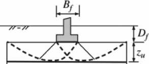
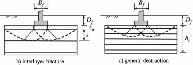
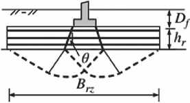
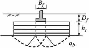
Researchers [10–15] have identified six potential types of destruction of geosynthetic bases, as shown in Figure 1. The destruction of the first layer, shown in Figure 1a, occurs when the distance from the foundation base to the uppermost reinforcement is too large and/or the filling soil is too weak. The destruction of the interlayer layer, as shown in Figure 1b, can develop when the distance between the geogrid is too large. A general fracture may develop inside a thick reinforced base with several layers of reinforcement, which includes one or more layers of reinforcement, as shown in Figure 1c. The applied stress at the base of the foundation extends to the underlying soil. When the reinforced zone is thin and the underlying soil is weak, the distributed foundation may fail due to the low strength of the weak soil, as shown in Figure 1d. When the reinforced foundation is thin but wide, and there is
reinforcement
a) destruction above the top layer of reinforcement
d) fracture through reinforcement under distributed load
e) destruction through reinforcement in a direct direction
f) destruction of soil reinforced with reinforcement and a soil cushion
Fig. 1. Types of destruction of the base reinforced with a geogrid
MANUFACTURING TECHNOLOGY FOR BUILDING MATERIALS AND PRODUCTS weak soil underneath, the foundation can penetrate the reinforced area, as shown in Figure 1e. Figure 1f shows the advance of the reinforced zone into weak soil due to the narrow-reinforced zone and the presence of underlying weak soil.
METHODS AND MATERIALS
The work of the bases with surface reinforcement
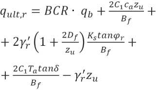
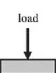
When static load tests on slabs are carried out on an unreinforced and reinforced foundation, typical results are obtained. Figure 2 shows that reinforcement increases the bearing capacity and modulus of deformation, as well as reduces the foundation draft [14, 15]. An increase in load-bearing capacity is often expressed by a load-bearing coefficient (BCR) as follows:
BCR = q ult,r ⁄ q ult,u , (1)
where: qult,u – is the maximum bearing capacity of non-reinforced soil; qult,r – is the maximum bearing capacity of reinforced soil.
MIF = kr ⁄ ku = Er ⁄ Eu , (2)
where: kr – is the reaction modulus of the reinforced foundation earthbed; ku – is the reaction modulus of the reinforced foundation earthbed; Er – is the modulus of elasticity of the reinforced foundation; Eu – is the modulus of elasticity of the non-reinforced foundation.
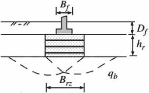
When the distance between the geogridges is large, destruction can occur between the uppermost and the next geogrid, as shown in Figure 1b. The ultimate bearing capacity in case of destruction of the intermediate layer is determined by the resistance of the base, the tensile strength of the uppermost geogrid, and the lateral contact resistance of the soil and the grid:
where BCR – is the coefficient of bearing capacity when the foundation is located at a depth of Df + zu (accepted in the range from 1.0 to 3.0); qb – is the maximum bearing capacity of an unreinforced foundation at a depth of the sole of Df + zu ; C1 – is a constant (2 for a square foundation and 1 for a solid foundation); ϕ r – is the friction angle of the reinforced filling; γ′ r – is the effective specific gravity of the reinforced filler; Ks – is the penetration coefficient proposed by Meyerhoff and Hannah; Ta – is the permissible tensile strength of the reinforcement; ca – is the adhesion between the perforating wedge and the reinforced filler; δ – is the angle of friction between the punching wedge and the reinforcing filler.
Of the parameters given in the formula, the most important are the tensile strength of the reinforcement, adhesion, and the angle of friction between the filler material and the reinforcing element.
Previous studies [15–18] have established that the tensile strength of geosynthetic materials is closely related to the mass per unit area. Geotextiles with a higher mass per unit area are usually stronger than lightweight geotextiles. It is also established for geosynthetics that the tensile strength depends on the deformation rate at which the sample is tested. At a low deformation rate, the measured strength tends to be lower and is achieved with a higher fracture strain value. Conversely, at a high strain rate, the measured strength tends to be higher and is achieved with less fracture strain.
When a geosynthetic is used to reinforce a soil mass, the bond between the soil and the geosynthetic must be sufficient to prevent the soil from sliding over the geo-

b
without reinforcement
with reinforcement
ground pressure
UOBBaugE-pos -os
Fig. 2. The difference between reinforced and non-reinforced soil
MANUFACTURING TECHNOLOGY FOR BUILDING MATERIALS AND PRODUCTS synthetic or pulling the geosynthetic out of the soil when mobilizing the tensile load in geosynthetics. The relationship between geosynthetics and soil depends on the interaction of their contact surfaces [16–20]. Thus, the interaction of soil-geosynthetics through friction at the interface and/or blocking characteristics is a key element in the characteristics of reinforced soil massifs. This is especially important for structures such as retaining walls, slopes, foundation bases, and embankments, as well as in other areas where the interaction between soil and geosynthetics is important to ensure the stability of the soil material to ensure the required slip or separation in the field. The interaction is mainly responsible for the transfer of stresses from the soil to the geosynthetics. In all cases, the interaction properties are used to determine the bond length of the geosynthetic material needed outside the critical zone. Two types of tests are currently used to assess the interaction of soil and geosynthetics. These include a forward shear test using a shear box and a tear-off/an-choring test [14–19].
The basic principle of these tests is that to move a solid object weighing W along a horizontal plane, the application of a horizontal force µW is required, where µ is the coefficient of friction between the object material and the plate material [18–24].
In the direct shear test, the shear resistance between the geosynthetic and the soil is determined by placing the geosynthetic and the soil in a direct shear box divided into upper and lower halves (Fig. 3a). The geosynthetic sample is fixed along the edge of the box, where the shear force acts. A constant normal force is applied to the box, representing the design stresses. By holding the lower half of the box stationary, the upper half is subjected to shear force according to a stepwise loading scheme or with a constant deformation rate. The shear force is recorded as a function of the horizontal displacement of the upper half of the shear box. The test is performed on at least three different normal compressive stresses selected to simulate the appropriate field conditions. The limit values of tangential stresses, usually peak and residual tangential stresses, are plotted relative to the corresponding values of the applied normal stresses. The installation diagram and the test results according to this scheme are shown below. The tests according to scheme b in Figure 3 are not discussed in this paper yet.
Laboratory study of the properties of geosynthetic materials
To study the physical and mechanical properties, the following types of materials were selected: hexagonal geogrid TX-170, polypropylene geogrid SD-40, uniaxial polypropylene geogrid CO-90, and nonwoven geotextile PP 250 (Fig. 5 a, b, c, d).
In this study, the main parameters to be studied are the tensile strength and elongation at break. These parameters are studied by conducting a tensile test, in which a tensile force is applied to the sample, and a curve of the dependence of the tensile force on elongation is constructed.
The tensile strength is usually determined by a wide band tensile test, which is performed on a 200 mm wide geosynthetic strip with an estimated length of 100 mm (ASTM, 2011b). A geosynthetic sample with a width of 200 mm across the entire width is captured by the clamps of a tensile strength testing machine and stretched in one direction at a predetermined constant speed until the sample breaks. During the stretching process, both the load and the strain are measured. However, this technique does not accurately simulate the operation of geosynthetic materials in a ground environment. At the base of the structure, the soil is loaded in steps, and, accordingly, the geosynthetic material is also loaded in steps. Therefore, in addition to tests on a bursting machine, where force is applied at a constant speed, tests were carried out with a stepwise application of a tensile load to failure, as well as tests of a long-term constant load to determine the threshold of plastic flow of the material.
The power frame installations shown in Figure 4 were used to carry out these tests.
The installations allow testing with stepwise and longterm loading of samples. A vise clamp made following GOST 32491-2013 was used to hold the prototypes.
Each power plant has upper and lower vise clamps. The upper clamp is pivotally fixed to the crossbar of the
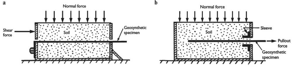
Fig. 3. The scheme of testing for the interaction of soil and geosynthetics: a – direct shear tests, b – pull-out test
MANUFACTURING TECHNOLOGY FOR BUILDING MATERIALS AND PRODUCTS
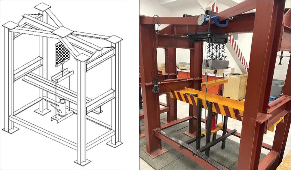
Fig. 4. Installation for testing geosynthetic materials
power frame, while the lower clamp is also pivotally connected to the upper frame channel of the thrust frame. With the help of a thrust frame and a jack, the tensile force is transferred to the test sample (Fig. 4). Deformations of the movable clamp are measured using an electronic deflection meter PSK MG-4, and the force value is measured with a dynamometer DMC 10 kN.
Another installation was used to identify the characteristics and behavior of geosynthetic materials under the influence of prolonged time. The difference between this installation is that the tensile force is applied using a rocker arm supported on a support channel. The gear ratio of the rocker’s arm is 1:10, and the load on the rocker’s arm is created by exemplary weights weighing 1.0–3.0 kg. This design solution allows you to maintain a given constant load for a long time. To measure the movement of the moving part of the clamp, electronic deflection meters PSK MG-4 with a division price of 0.01 mm are used. Two deflection meters are used, located on both sides of the sample, to determine the average deformation. An electronic dynamometer DMS 10 kN is used to measure the axial force from the power jack.
Since the work of geosynthetic material is assumed to be part of the soil, together with the soil of the foundation of buildings and structures, in addition to the generally accepted methodology according to GOST 32491-2013, the features of the methodology for studying soil properties according to GOST 12248.1-2020 were used. Recommendations were used regarding the exposure of the values of the loading stages and the time of conditional stabilization of deformations during tests of gravelly and sandy soils.
The tensile strength is determined by the tensile test of a wide strip with a width of 200 mm with an estimated length of at least 100 mm. The test sample with a width of 200 mm is gripped along the entire width with standard tensile strength test clamps and stretched in the vertical direction. The load on the sample is applied in steps of 15 kN and maintained from 0.5 to 1.0 hours until the deformations are stabilized. The criterion for conditional stabilization of deformation is the rate of stamp precipitation, which does not exceed 0.1 mm during the specified time. During the stretching process, the load is measured by a dynamometer. The increase in the true calculated length of the sample at any given load is measured using electronic deflection meters of the PSK-MG4 brand (Fig. 5).
The width of the sample is preserved more than its length since some geosynthetics tend to shrink under load around the calculated length. The large width reduces the shrinkage effect of such geosynthetic materials and, approaching the conditions of flat deformation, more accurately simulates the deformation experienced by geosynthetic material when introduced into the soil in the field.
The preparation and loading of samples during longterm tests are like rupture tests. During long-term tests, reference weights weighing 3 kg each were used to transfer the load to the samples through a rocker’s arm with a gear ratio of 1:10. The load was applied in steps of 0.1
MANUFACTURING TECHNOLOGY FOR BUILDING MATERIALS AND PRODUCTS
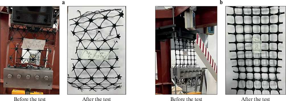
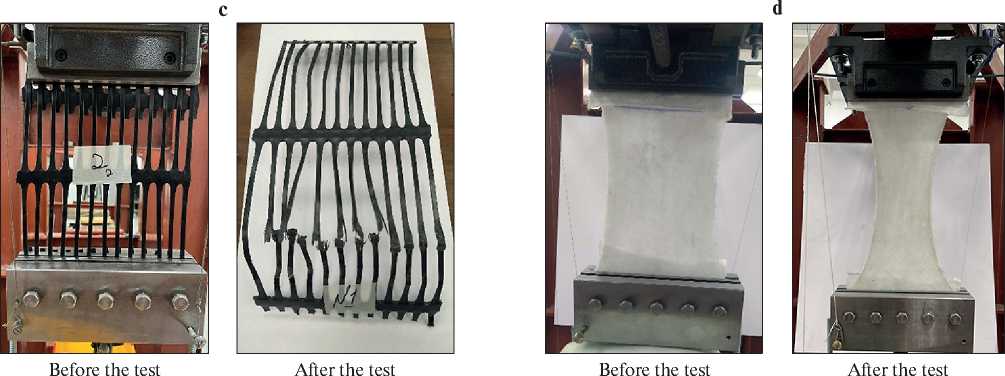
Fig. 5. Types of materials before and after the test: a – type of hexagonal geogrid TX-170; b – type of polypropylene geogrid CD-40; c – uniaxial geogrid CO-90 polypropylene; d – uniaxial geogrid CO-90 polypropylene
of the maximum tensile loads according to the passport data of the geosynthetic material. The deformation rate of the sample, not exceeding 0.1 mm over a period of 0.5 to 1.0 hours, was taken as the criterion for conditional stabilization of deformation. However, for some materials, such as geotextiles, the tests lasted several days (Fig. 5).
The samples were prepared under the recommendations of GOST 32491-2013. Samples with a nominal width of 200 mm (excluding fringe) and sufficient length to ensure that the distance between the clamps is at least 100 mm were prepared for the test; in this case, the length of the sample should be parallel to the direction of application of the tensile force (Fig. 5).
The test sample must contain at least one row of nodes or transverse elements, excluding nodes of transverse elements fixed in clamps. For materials with a pitch of less than 75 mm, the sample must contain at least four complete stretchable elements (ribs) in the width direction. Materials with a pitch of more than 75 mm, but less than 120 mm, must contain at least two complete stretchable elements in the width direction. For materials with a pitch of more than 120 mm, it is allowed to test single ribs (Fig. 5).
The tensile strength Tmax , kN/m, is calculated directly from the data of the test-breaking machine according to the formula:
Tmax = Fmax * c ,
where Fmax – is the registered maximum force, kN; c – is the value derived from formula (4) or (5), respectively.
For non-woven, woven, and threadbare geotextiles, as well as geosynthetic clay barriers (bentonite mats)
c = 1 / B ,
where B - is the average nominal width of the sample, m.
MANUFACTURING TECHNOLOGY FOR BUILDING MATERIALS AND PRODUCTS
For geogrids or similar geosynthetic materials with an open structure c = Nm / ns, (6)
where: Nm – is the average number of stretchable elements over a width of 1 m of the test sample for the test; ns – is the number of stretchable elements within the test sample for the test.
The deformation (elongation) as a percentage at maximum load should be recorded and indicated in the test report with an accuracy of 0.1%. Deformation (elongation) at maximum load is defined as a registered increase in the length of the test sample (in millimeters) from the pre-tension level to the maximum load, multiplied by 100 and divided by the true calculated length (in millimeters).
The true design length is defined as the nominal design length plus the elongation from the start of the test to the pre-tension level.
Testing of properties at the soil-geosynthetics boundary
The scheme (Fig. 3a) was used for testing, according to the principle of direct shear testing. The design diagram of the device is shown in Figure 6. The design of the shear device provides an initial vertical pressure on the sample (from the weight of the stamp and measuring instruments on it) of no more than 0.025 MPa.
A direct shear test can be performed to study the friction characteristics along the geosynthetic-geosynthetic interface by placing a geosynthetic sample between the lower and upper halves of the shear device holder.
Two series of tests of gravel soil were carried out in the shear device. The first series was carried out to determine the strength parameters of gravel soil only in accordance with GOST 12248.1-2020. In the second series, a geogrid was placed in the shear plane of the shear device. To conduct experiments with geosynthetic grids, a modified version of the single-plane slice device was used, the general view of which is shown in Figure 7. The device is equipped with a special device for fixing geosynthetic material.
The operation of the device is organized in the power loading mode (controlled deformation mode) with the ability to control both tangential stresses and shear deformations at any time. The movement of the lower movable holder of the device is created using a hydraulic jack.
To carry out the test, the device clips are filled in layers with gravel soil, compacting it every 5–7 cm. The soil fills the cylinder until its surface is 5 cm below the level of the upper cage. Then a stamp, jacks, and sensors are installed to measure vertical and horizontal deformations. Shear tests are carried out at least three times at compressive normal stresses, simulating the operation of the system in the field.
The above-described design of the vertical loading system ensures uniform transmission of normal pressures to the soil sample, which contributes to the uniformity of the deformed state of the soil in the cut plane.
RESULTS AND DISCUSSION
The analysis of the results shows that the tests according to the step loading scheme with an exposure to stabilize a certain level and a comparison of the results with the passport data obtained according to GOST 32491 revealed the following results (Tab. 1). For all materials,
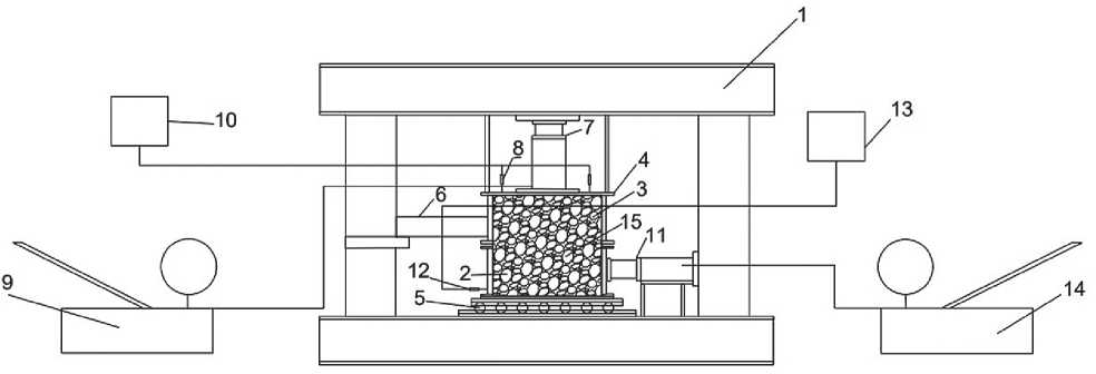
Fig. 6. General diagram of a shear device with a sample diameter of 41 cm: 1 – power frame; 2 – movable cage; 3 – fixed cage; 4 – upper stamp; 5 – balls on skids; 6 – stop; 7 – vertical jack; 8 – displacement sensors; 9 – manual pumping station for vertical 10 – a unit for measuring vertical movements; 11 – a jack for horizontal movement; 12 – a deflection meter; 13 – a unit for measuring horizontal movements; 14 – a manual pumping station for a horizontal jack; 15 – a soil sample
MANUFACTURING TECHNOLOGY FOR BUILDING MATERIALS AND PRODUCTS
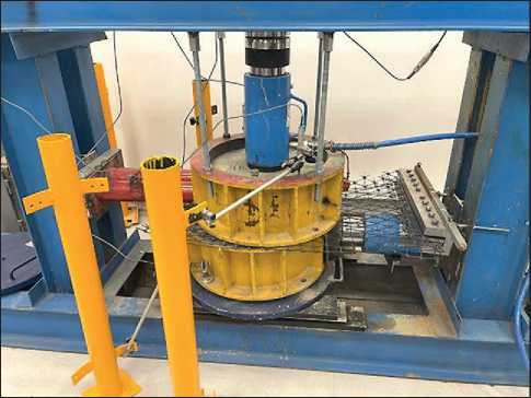
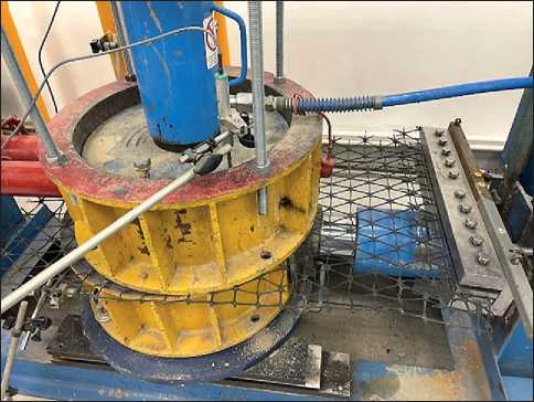
Fig. 7. View of a modified shear device for testing with geosynthetics
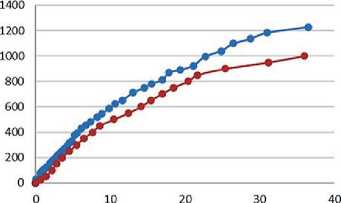
there is a decrease in tensile strength, which ranges from 28% to 42% for geogrid types. The elongation at break decreased for the hexagonal and biaxial geogrid by 8.6% and 30%, respectively. For a uniaxial geogrid, the rela- tive elongation increased by 45%. For geotextiles, the test conditions also had an impact on its mechanical properties. The tensile strength decreased by 15.7%, while the elongation increased by 26.5% (Fig. 8).
Table 1
Test results of geosynthetic materials
|
No. |
Type of material |
Material density g/m2 |
Maximum tensile load F max , kN |
Test results data |
Passport data of materials |
||
|
Tensile strength, T max , kN/m |
Elongation at break not less than, % |
Tensile strength, kN/m |
Elongation at break not less than, % |
||||
|
Hexagonal geogrid TX-170 |
|||||||
|
1 |
Ж |
290 |
3.16 |
14.7 |
13.7 |
21 |
15 |
|
Polypropylene geogrid SD-40 «Geomax» |
|||||||
|
2 |
530 |
5.73 |
28.65 |
7.3 |
40 |
10.5 |
|
|
Uniaxial geogrid CO-90 polypropylene |
|||||||
|
3 |
凰 |
690 |
11.15 |
51.5 |
14.5 |
90 |
10 |
|
“Non-woven geotextile” PP, 250 |
|||||||
|
4 |
250 |
0.70 |
7.0 |
25.3 |
8.3 |
20 |
|
MANUFACTURING TECHNOLOGY FOR BUILDING MATERIALS AND PRODUCTS
b
а
—♦— Sample 1
—♦— Sample 2
Deformation, mm
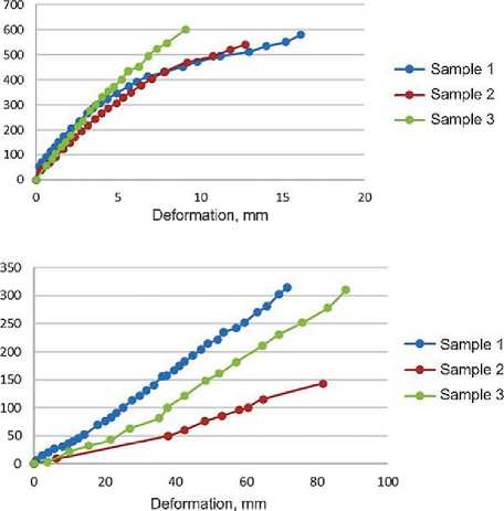
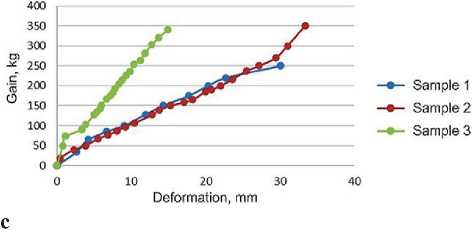
Fig. 8. Stretching diagrams of samples: a – hexagonal geogrid TX-170; b – polypropylene geogrid SD-40; c – uniaxial geogrid CO-90; d – “Non-woven geotextile”
The resulting differences in the properties of materials can be explained by their special characteristics as polymer materials, which manifest themselves differently when loaded with a constant strain rate and when loaded in stages with strain stabilization control. The viscoelastic behavior of geosynthetic materials can lead to misleading results in both long-term and rapid tensile tests. Tests carried out to obtain design parameters must also consider long-term conditions and the influence of the surrounding soil. It was found that geosynthetic retention in the soil in the field and the associated adhesion of soil particles to the geosynthetic structure has a significant effect on stress-strain properties.
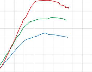
The shear tests were carried out with gravel soil with a maximum particle size of no more than 30 mm and a content of large fractions of no more than 30%. The tests were performed at constant vertical loads of 0.1 MPa, 0.2 MPa and 0.3 MPa. The main results are shown in Figure 9.

General shear resistance diagram
mxd іакю косо гол» 2ьл» ма» »лю шоо «у ою мха»
Movement of the device holder, mm
^— Experience 1
^— Experience 2
^^ Experience 3
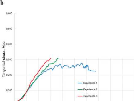
General shear resistance diagram
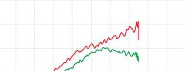

Fig. 9. Test results in a shear device: a – shear resistance of gravel soil (adhesion C = 0.2583MPa, angle of internal friction φ = 62°); b – shear resistance with a geogrid in the shear plane (adhesion C = 0.16MPa, angle of internal friction φ = 49.4°)
MANUFACTURING TECHNOLOGY FOR BUILDING MATERIALS AND PRODUCTS

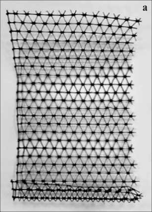
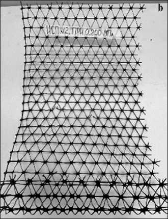
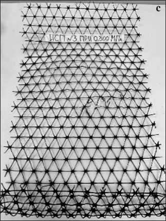
Fig. 10. View of the hexagonal lattice after the shear test: a – at a voltage of 100kPa; b – at a voltage of 200kPa; c – at a voltage of 300kPa
The shear resistance is characterized by both peak and residual values. The peak strength values for gravel material are specific adhesion C = 0.258 MPa and internal friction angle φ = 62°. The residual strength is not clearly fixed, so it is not being discussed yet. In tests with a geogrid in the shear plane, peak values show a specific adhesion of C = 0.16 MPa and an internal friction angle of φ = 49.4°.
The shear resistance process involves the movement and rolling of soil particles at the lattice boundary. The activity of particle participation in the shift indicates the presence of traces of local geogrid gusts. At a normal voltage of 100 kPa, the traces of gusts are almost invisible (Fig. 10a). At normal stresses of 200 kPa and 300 kPa, the traces of gusts become larger as stresses and deformations increase (Fig. 10 b, c). Thus, it should be stated that the process of shear resistance at the boundary of geosynthetics and soil should be considered as a complex shear process depending on the type of geosynthetic and granulometric properties of the soil material.
Earlier studies [25–29] showed that the angle of internal friction is φ = 43°, 38°, 36°, 35°, 41° accordingly, for sand-sand, sand-needle-punched non-woven geotextile, sand-thermally bonded non-woven geotextile, sand-lightweight woven geotextile and sand-geogrid (calculated according to BS EN ISO 13738 (BSI, 2004a)). Our research has shown that the friction angle for gravel soil with a geogrid is 49.5°. This value fits into the general pattern of the above data. Usually [14] the friction angle for soil geotextiles is taken between (2/3) φ and φ, where φ is the angle of soil shear resistance. We obtained the angle of internal friction for gravel soil as φ = 62°. Therefore, the ratio of the friction angle for soil-geotextile was 3/4 φ. We believe that this result is explained by the large fraction of gravel soil and the size of the geogrid cells.
As noted by other researchers [1, 2, 4, 5, 8, 12], a direct shear test is not suitable for determining the exact relationship between stress and strain due to the uneven distribution of shear and displacement forces within the chamber of a shear device. The total resistance can be a combination of sliding, rolling, and adhesion of soil particles and geosynthetic surfaces, as well as shear stress inside the geosynthetic sample. The shear resistance may vary on different sides of the geosynthetic material and vary depending on the direction of the shear relative to the orientation of the geosynthetic material.
CONCLUSION
In conclusion, the following conclusions can be drawn:
-
1. Most of the intensively built-up territory of southern Kazakhstan is located on soils with specific properties. These include subsidence, loess, swelling, and waterlogged weak soils. It is known from construction practice that during the construction of buildings in such conditions, measures are required to strengthen the soils of the foundations.
-
2. Hardening of the surface layers of the soil using the method of replacement with a more durable material is the most common and technologically advanced. However, the method has limitations on the depth of the cushion (5-6 meters is recommended for Kazakhstan) and the type of material used to replace it. In Kazakhstan, local clay soil is usually used as a newly compacted soil, various methods are used to improve the physical and mechanical properties of which. One of these methods
-
3. Tests of geosynthetic materials in kinematic mode have shown that for all materials there is a decrease in tensile strength. The reduction ranges from 28% to 42% for different types of geogrids. The elongation at break decreased for the hexagonal and biaxial geogrid by 8.6% and 30%, respectively. An increase in relative elongation was noted for a uniaxial geogrid. According to geotextile, the tensile strength decreased by 15.7%, and the elongation increased by 26.5%. The data obtained most likely reflect the long-term strength of the materials.
-
4. Tests on a modified shear device, conducted on the example of gravel soil, showed that the effectiveness of improving the mechanical properties of soil cushions reinforced with geosynthetic materials depends on the accuracy of determining the properties at the geosyntheticsoil boundary.
-
5. The data presented in the article are obtained only for static conditions of reinforced soil cushions. The influence of seismic action on the hardened base can reveal factors that will adjust the performance of reinforced cement columns, as well as to the performance of hardened soil massifs. These factors are to be studied in our subsequent studies and will be used in recommendations for real projects.
MANUFACTURING TECHNOLOGY FOR BUILDING MATERIALS AND PRODUCTS is hardening using geosynthetic materials. In this case, a composite array with physico-mechanical properties is formed, which is determined by the properties of the soil and geosynthetic material.
References The use of geosynthetic materials to increase the bearing capacity of soil cushions
- Sitek W., Kozłowski F., Kiersnowska A., & Dohojda M. The application of hexagonal geogrid as a reinforcement element of the base of a road embankment. Acta Scientiarum Polonorum. Architectura. 2023; 22: 102–109. https://doi.org/10.22630/aspa.2023.22.11
- Dhanya K. A., Vibha S., & Divya P. V. Coupled Flow-Deformation Analysis of MSE Wall Reinforced with Hybrid Geogrids. International Journal of Geosynthetics and Ground Engineering. 2023; 9(4). https://doi.org/10.1007/s40891-023-00466-7
- Razeghi H.R. & Ensani A. Clayey Sand Soil Interactions with Geogrids and Geotextiles Using Large-Scale Direct Shear Tests // International Journal of Geosynthetics and Ground Engineering. 2023; 9(2). https://doi.org/10.1007/s40891-023-00443-0
- Abdi M.R., Tabarsa A. & Haghgouy P. Evaluation of Soil–Geometrically Modified Geogrid Interaction in Direct Shear Mode. International Journal of Geosynthetics and Ground Engineering. 2023; 9(5). https://doi.org/10.1007/s40891-023-00479-2
- Shi D., Niu J., Zhang J., Chao Z. & Fowmes G. Effects of particle breakage on the mechanical characteristics of geogrid-reinforced granular soils under triaxial shear: A DEM investigation. Geomechanics for Energy and the Environment. 2023; 34. https://doi.org/10.1016/j.gete.2023.100446
- Lukpanov R., Dyussembinov D., Zhantlesova Z. & Yenkebayeva A. Evaluation of tensile strength characteristics of geosynthetic materials designed to ensure embankment stability. Technobius. 2023; 3(2): 0036. https://doi.org/10.54355/tbus/3.2.2023.0036
- Mohammed S.A., Naimi S. & AbdulKareem A.H. The effect of geogrid reinforcement of embankment over soft foundation. Periodicals of Engineering and Natural Sciences. 2022; 10(6): 5–27. https://doi.org/10.21533/pen.v10i6.3345
- Jin J., Liang X., Yang G. & Zhou Y. Test Studies on Geogrid–Soil Interface Behavior under Static and Dynamic Loads. Sustainability (Switzerland). 2022; 14(7). https://doi.org/10.3390/su14074299
- Gao Y.X., Zhu H.H., Ni Y.F., Wei C. & Shi B. Experimental study on uplift behavior of shallow anchor plates in geogrid-reinforced soil. Geotextiles and Geomembranes. 2022; 50(5): 994–1003. https://doi.org/10.1016/j.geotexmem.2022.06.006
- Jayanandan M. & Viswanadham B.V.S. Evaluation of the Behavior of Geogrid-Reinforced Soil Walls Subjected to Rainfall Through Centrifuge Model Tests. International Journal of Geosynthetics and Ground Engineering. 2022; 9(6). https://doi.org/10.1007/s40891-023-00487-2
- Lu L., Chen B., Wang Z., Wang S. & Arai K. Study on seismic stability and performance of reconstruction embankment using geogrid reinforced soil technology. Transportation Geotechnics. Elsevier Ltd. 2024; https://doi.org/10.1016/j.trgeo.2023.101148
- Eissa A., Alfaro M., Bartz J.R., Bassuoni M.T. & Bhat S. Soil-Reinforcement Interaction of a Geogrid–Geotextile Composite. International Journal of Geosynthetics and Ground Engineering. 2023; 9(6). https://doi.org/10.1007/s40891-023-00506-2
- Kumar S. & Singh S.K. Subgrade soil stabilization using geosynthetics: A critical review. Materials Today: Proceedings. 2023; https://doi.org/10.1016/j.matpr.2023.04.266
- Cui K., Zhang D., Li Q., Yang S. & Zhang H. Experimental investigation on the accumulated strain of coarsegrained soil reinforced by geogrid under high-cycle cyclic loading. Geotextiles and Geomembranes. 2023; 51(1): 233–244. https://doi.org/10.1016/j.geotexmem.2022.11.001
- Liu W., Li H., Yang Y., Xu P., Dai Z., Yang G. & Wang Z. Study on Improvement Characteristics of a Novel Geotextile with Stitched Transverse Ribs. Applied Sciences (Switzerland). 2023; 13(3). https://doi.org/10.3390/app13031536
- Gao J., Liu L., Zhang Y. & Xie X. Deformation mechanism and soil evolution analysis based on different types geogrid reinforced foundation. Construction and Building Materials. 2022; 331. https://doi.org/10.1016/j.conbuildmat.2022.127322
- Derksen J., Fuentes R. & Ziegler M. Geogrid-soil interaction: Experimental analysis of factors influencing load transfer. Proceedings of the Institution of Civil Engineers: Geotechnical Engineering. 2022; https://doi.org/10.1680/jgein.21.00110
- Wang G., Zhang X., Liu X., Chang Z. & Liu Z. Large-scale Field Tests of the Performance of Geogrid-reinforced Piled Embankment over Soft Soil. KSCE Journal of Civil Engineering. 2024; 28(2): 655–672. https://doi.org/10.1007/s12205-023-0837-y
- Bekbasarov I., Nikitenko M., Shanshabayev N., Atenov Y. & Moldamuratov Z. Tapered-prismatic pile: driving energy consumption and bearing capacity. News of the National Academy of Sciences of the Republic of Kazakhstan, Series of Geology and Technical Sciences. 2021; 6(450): 53–63. https://doi.org/10.32014/2021.2518-170X.119
- Khomyakov V.A., Gumenyuk V.V. & Dursynov S.B. Restoring the serviceability of buildings in areas where loess macroporous foundations are widespread. Industrial and Civil Construction. 2022; 8: 48-56.
- Khomyakov V.A., Shalkaev B. & Emenov Yu.M. Application of various methods of soil strengthening for stabilization of slopes in seismic areas. Scientific and practical magazine for designers and builders. 2020; 1: 11-14.
- Das K., Chattaraj S. & Bandyopadhyay K. Review on the Application of Geosynthetic for Ground Improvement. Lecture Notes in Civil Engineering. 2023; 298. https://doi.org/10.1007/978-981-19-6774-0_8
- Suleimenov Z.T., Sagyndykov A.A., Moldamuratov Z.N., Bayaliyeva G.M., & Alimbayeva Z.B. High-strength wall ceramics based on phosphorus slag and bentonite clay. Nanotechnologies in Construction. 2022; 14(1): 11–17. https://doi.org/10.15828/2075-8545-2022-14-1-11-17
- Shukla S.K. An Introduction to Geosynthetic Engineering. In An Introduction to Geosynthetic Engineering. 2016. https://doi.org/10.1201/b21582
- Korobova O. & Loshchev V. Technology for Strengthening Earth Mound’s Foundations, Reinforced with Geosynthetic Materials. IOP Conference Series: Materials Science and Engineering. 2020; 953(1). https://doi.org/10.1088/1757-899X/953/1/012063
- Thamer L. & Shaia H. The Effect of Geotextile Layers and Configuration on Soil Bearing Capacity. Mathematical Modelling of Engineering Problems. 2021; 8(6). https://doi.org/10.18280/mmep.080608
- Khomyakov V.A., Gumenyuk V.V. & Dursynov S.B. Comparison of the results of calculation of the bases of high-rise buildings PC Midas and PC Plaxis. Bulletin of Kazakh Leading Academy of Architecture and Construction. 2022; 84(2): 328–338. https://doi.org/10.51488/1680-080x/2022.2-36
- Lavrov A.S., Khomyakov A.P. & Nikulin V.A. Methodic for simulation of mixing the processes with large content of the solid phase. Central Scientific Library of the Urals Branch of the Russian Academy of Sciences. 2018; 151–162. https://doi.org/10.32460/ishmu-2018-6-0018
- Jakiyayev B.D., Moldamuratov Z.N., Bayaliyeva G.M., Ussenbayev B. U. & Yeskermessov Z.E. Study of local erosion and development of effective structures of transverse bank protection structures. Periodicals of Engineering and Natural Sciences. 2021; 9(3): 457–473. https://doi.org/10.21533/pen.v9i3.2191
