To the question of establishing safety coefficient and assurance coefficient at a given probability of non-destruction of load-bearing structures

Author: Pokhabov Yu. P., Shendalev D. O., Kolobov A. Y., Nagovitsyn V. N., Ivanov E. A.
Journal: Siberian Aerospace Journal @vestnik-sibsau-en
Section: Aviation and spacecraft engineering
Article in issue: 1 vol.22, 2021.
Free access
Ensuring high reliability of unique high-critical products at the design stage is an actual task that the aerospace industry faces. For high reliability indicators, at the design stage, it is necessary to ensure the basic property of the product – its strength, with a high probability of non-destruction. It is provided by introducing the corresponding coefficients – «safety coefficient» and «margin of safety» into the strength calculations. The necessity in these coefficients is based on the spread of values of external loading factors: magnitude of forces, combination of forces, kind of actions, place of connection, etc. In this case, the safety coefficient is related to external factors. The margin of safety refers to internal factors: the spread of the mechanical characteristics of the product material, the spread of the geometric dimensions of the product, etc. To determine, with a given probability, the safety coefficient and margin of safety, it is necessary to know their dependence on the combination of spread of external and internal factors. The purpose of this work is to determine the mathematical connection between the internal factors of the spread and the safety coefficient, external factors of the spread and the margin of safety, the combination of these factors and the probability of non-destruction of structures. In this work the values of internal and external factors, which affect the strength and probability of non-destruction of the product and have the boundaries of the spread of their values, using the tools of probability theories, were characterized as random variables, the values of which are determined by the distribution density, expected value and variance. I this work there was found a high dependence of the product strength on the spread of its geometric characteristics and tools were defined to determine the total spread of the values of the main strength characteristics of the product with a given probability of non-destruction. The practical significance of the results of this work can be achieved in the aerospace industry, in particular, at the design stage of unique high-critical products.
Safety coefficient, assurance coefficient, theory of probability, strength assurance, coefficient of variation, load, resistance.
Short address: https://sciup.org/148321795
IDR: 148321795 | UDC: 539.4 | DOI: 0.31772/2712-8970-2021-22-1-166-176
Text of the scientific article To the question of establishing safety coefficient and assurance coefficient at a given probability of non-destruction of load-bearing structures
Introduction. Safety coefficient, according to GOST R 56514-2015, takes into account the inaccuracy of the theoretical and experimental determination of loads and load-bearing capacity, as well as the random spread of these loads, and the margin of safety – the excess of the natural strength of the material in comparison with the necessary for its operation under these conditions [1]. Thus, when talking about safety coefficients, external loads are meant and the safety margins are mainly used to select the mechanical characteristics of structural materials.
In the deterministic formulation of strength problems, the safety coefficient f is used to determine the calculated load NP
NP = f · N, where N is the operating load.
N is understood as the value of the load and the loading mode (the dependence of loads on time), implemented in the considered case of loading during operation.
The margin of safety of the structural element is determined by the formula
„ N limit „ alimit
П NP , P , where Nlimit - the value of the limit load; alimit - the limit stress; оP- the equivalent design stress.
If to consider the strength in the category of internal forces of the structure, then for the simplest combinations of types of structural elements and loads, the load-bearing capacity R , in the form of nondestructive internal loads, is equal to
R= ^N) > Nlimit =n- f - N, Л
where σ( N ) is the maximum permissible local stresses caused by the load N ; λ is the coefficient depending on the cross – sectional dimensions of the structural elements.
The value of σ ( N ) depends on the acting loads, for example, in a complex stress state (both non-zero normal and tangential stresses), one of the four criteria for the ultimate stress-strain state (mechanical strength theory) is used [2]. In turn, λ depends on the size of the cross-section of the structural elements [3]. For example, for a stretchable rod
-F for a bendable rod
. a-1
Л =----,
WZ for a twisted rod
x = ^, WK where F is the cross-sectional area; α is the coefficient depending on the conditions of fixing the beam and the load; l is the length of the rod; WZ is the moment of resistance of the cross-section of the rod during bending; WK is the moment of resistance of the cross-section of the rod during twisting.
For a normal distribution R and N (the sign of the functional dependence on time is omitted hereafter), without taking into account the correlation dependence, the probability of non-destruction of structural elements, that is, the probability that the load-bearing capacity R will be greater than the operating load N , is defined as
P = Aad{ R > N } =Ф ( z) = Ф
m R - m N 2 _2
^\/aR + aN J where Φ(z) is the normal distribution function (Laplace function); mR, mN are the mathematical expectations of R and N ; σR, σN are the rms deviations of R and N.
Under normal laws of distribution of random values of load and resistance, the failure model according to the “load-resistance” scheme has the following form (Fig. 1).
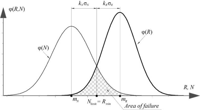
Fig. 1. Model of failure on the scheme “load – resistance” by the law of normal distribution random variable Рис. 1. Модель отказов по схеме «нагрузка – сопротивление» при нормальном законе случайных величин
As follows from Fig. 1, the maximum probability of non-destruction of structural elements is achieved by dividing the average values of m R to m N , as well as by reducing σ R and/ or σ N . In this case, the minimum load capacity and the maximum load always lie in the range from m R to m N and, provided z > 0, are defined by the expressions
R min = m R – k R · σ R ,
Nlimit = mN + kN · σN, where kR, kN are numerical coefficients that characterize the probability of deviation of a random variable from the mathematical expectation, which for highly reliable systems are set from 3 to 6 (based on the rules of three sigma or six sigma) [4].
The case when
R min = N limit ,
for any method of improving reliability, it determines the minimum failure area (see Figure 1).
Taking into account the expressions (1)–(5), we get n = Rmin , Nlimit where n is the generalized coefficient of reliability and safety margin, which simultaneously takes into account the operating loads and the characteristics of the structural material, which is equal to n = η · f.
Mathematical expectations in expression (2), subject to expression (5) (at the intersection of the distribution density curves according to Fig. 1) taking into account (1), (3)–(6) you can define dependencies
mR =
R min
1 - kR’°R
n - N limit
1 - kR’°R
N limit m N = ,
1 +kN- UN where υR, υN are the coefficients of variation of the load-bearing capacity (strength) and loads.
The values of υ R , υ N are determined by the formulas
^R
U R -mR
° N U N = .
N m N
The standard deviations in the expression (2), taking into account (7)–(8), can be represented as
° R = U R- mR =
n -Ц r • N iimit
1 - kR’UR
° N = U N ' mN
U N ' N limit
1 + kN’UN
Taking into account (7)–(10), the expression (2) for the most loaded structural element takes the form
P =ф
n
1 — k Rl U R
—
1 +kN'UN
n-OR
U N
,
1 kR ’U
1 + kN -O N у
Taking into account the three sigma rule, the formula (11) can be written as [5; 6]
n1
—
P =ф
1 — 3-о R 1 + 3-o N
_njR^_ + U N
1 — 3-oRJ (1 + 3-oN у
Assume that υ R = υ N = 10 % [5]. Then, for a generalized safety margin of n = 1.5 (for example, for f = 1.5 and = 1.0), the value of the normalized random variable is = 6.03, which corresponds to the probability of non-destruction of the structure more than 0.999999999 [7].
The use of formulas (11)–(12) makes it possible to use safety coefficients and safety margins to control the strength reliability of the structure at the design stage.
Safety coefficients f , as a rule, reflect the industry specifics of approaches and methods for processing statistical information about loads reflected in particular strength standards, taking into account the completeness and accuracy of information about the values and repeatability of operational loads, as well as the volume of experimental testing, the accuracy of reproducing loading modes during tests. In particular, for load-bearing structures of automatic spacecrafts, the recommended safety coefficients according to GOST R 56514–2015 can be used, which, as a rule, are assumed to be equal to 1.3 to 1.5, but in some cases, they can reach values of 2.0 to 2.6.
The safety margins η are usually assigned based on the values of the coefficients of variation for steels υ R = 5÷9 % and for aluminum alloys υ R = 4÷6 % [8; 9], which corresponds to the acceptability of calculations according to the formula (12). However, this approach takes into account only the natural strength of the material, without taking into account the variation in the geometric characteristics of the structure that affect the value of the resistance of the structure to external loads [2]. At the same time, it is known that the values of the safety margin coefficients are inextricably linked with the assumptions laid down in the calculations, and therefore require precise formulation of the calculation methods used, requirements for the accuracy of the initial data, etc. [10].
Example. Consider the effect of variations in the geometric dimensions of the cross-section of the structural element on the margin of safety on the example of an antenna cantilevered on board the spacecraft, shown in Fig. 2, which is affected by transverse overloads n x of the active flight period. The antenna body is made of an isotropic material with a tensile strength [ σ ] = 140·106 Pa. The antenna has a constant cross-section in the form of a round tube D = (65.5 ±0.3) 10–3 m and d = (64.1±0.4) 10–3 m. The mass of the antenna m is evenly distributed along the length of L .
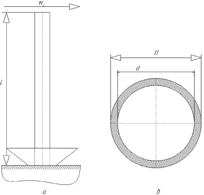
Fig. 2. Schematics attachment ( a ) and cross-section of antenna ( b )
Рис. 2. Схема закрепления ( а ) и сечение антенны ( б )
The external distributed load on the antenna q N is equal to
qN= f ⋅nx⋅
m⋅g L
where g is the acceleration of gravity.
The bending moments in the antenna are equal to
Mn = qN^L-
,
From formulas (13)–(14), it can be seen that the bending moments acting on the antenna are determined by certain external factors of the operating conditions, which are expressed in terms of n x and to some extent are characterized by the properties of the real structure (in this case, this is the mass m and the length of the console L ), which determine (affect) the amount of external loads. The random variation of the parameters of external loads associated with discrepancies in their theoretical and experimental determination is taken into account by the safety factor f . The experience accumulated in the rocket and space industry [11; 12] suggests that under the existing combinations of operating conditions and the accepted design and power schemes of the spacecraft, the maximum values of the load variation coefficients will not exceed υ N = 0.1 [5], and, accordingly, the recommendations of GOST R 56514–2015 may be acceptable for choosing the values of the safety coefficients.
Now consider the internal bending moments M R in the cross sections of the rod, which resist to the external load M N (14)
n>oVD4 -d4)
,
Mr =----------
R 32 ■ D where σ is the normal operating stress.
Provided that the strength is preserved and considering (1), there is
^■ [ ct 1 ^ ( d 4 - d 4 )
Mr ^ V--------
■
R 32 ■ D
Taking into account the normal distribution law of the random variable (2), the total rms values of the resistance to external loads σ R are defined as [13]
° R =
X 2
dM
-SRI ■("D• D) +
\ 2
8-M R I
6[°]J
where и D is the coefficient of variation of the outer diameter;
и d - the coefficient of variation of the
inner diameter; U [c]
–
the coefficient of variation of the
permissible stress of the material.
Or, for clarity, in the form of
- Г”- , 2 . 2
° R = \° R (1) '° R (2) '° R (3) ■
Based on (15), (16), the coefficient of variation of the bearing capacity υ R is a function that depends on и D , и d , U [c] . The material variation coefficient set for simplification, based on the generally accepted calculation practice U [c] =10 % [5]. Then the coefficient of variation и D for the outer diameter D can be calculated by the formula
σ
U D = — , mD where mD is the mathematical expectation of size D (in our case mD = 0.0655 m); σD is the rms deviation of D.
The value of σ D can be determined by the formula
1j 2
CT D ^pfE( mD - xi) , where xi is all the values of the measurement parameters in the specified range; j is the number of measurements.
Because there are strict limits on the maximum size, we can take j = ∞. Thus, the formula for calculating the final value of the coefficient of variation и D will be as follows
иD - lim j ——^
1j 2
— • £ ( m D - x i ) j 1 i - 1
m L
.
Taking into account (17), the following values were obtained for the sizes D and d : и D = 0.26% and и d = 0.36 %.
Thus, taking into account (15), (16) we get:
ст Ж1) -
л•[ст]• D2 1 ^И^ D-d4)
---
•(uD ' D) ,
ст R (2) -
[ст] •n^ d4 •u d 8D
,
СТ R 3) -
ЧстИ ст] •( D4 - d4)
32 • D
.
To illustrate the sequentially made
contribution of each component to the standard deviation σ R , the calculation is
Thus,
ст Ж1)
^140•Ю6 • 0.06552
ст R 2) -
ст R 3) -
1 ^•140•Ю6 ^(0.06554 - 0.06414)
----
0.06552
X
х(0.0026• 0.0655)-39.34 N-m
(140•Ю6)•л•0.06414 • 0.0036
8 • 0.0655
- 51,01 N-m
л-(140•Ю6)• 0.1^(0.06554 -0.06414)
32 • 0.0655
- 31.98 N-m.
стR -VCTR(1) +CTR(2) +CTR(3) - 71.92 N^m.
The presented calculations show that the influence of the strength of the material has a much smaller impact than the spread of geometric characteristics, and the total coefficient of variation of the bearing capacity will be equal to
vR = ^R =-----^^=-------- 71,92 -------— = 71.92 = 0.225.
mR n-[n]-(D4 -d4) n-140-106 .(0.06554 - 0.06414 ) 319.78
32 - D 32 - 0.0655
It means that the considering of variations in the geometric dimensions of the cross-section can increase the spread of the load-bearing capacity of the structure up to 2.25 times. This leads to the fact that at υN = 10 % and υR = 22.5 %, there are no acceptable combinations of safety factors and safety margins that would ensure the non-destruction of critical elements with a probability of P = 0.999999999. According to formula (12), in this case, with a generalized safety margin of n = 1.5, the probability of non-destruction P = Φ(3.69) = 0.99989 can be achieved. To increase the reliability in this case, it is necessary to exclude the spread of the dimensions of the geometric sections, which is possible when calculating the safety margin, taking into account the minimax approach [14; 15] and when the calculation of the moment of resistance of the section is made at the minimum possible external diameter D and the maximum possible internal diameter d of the antenna.
Conclusion
-
1. The assignment of safety coefficients and safety margins when calculating the strength of structural elements should be made based on the required reliability indicators of products.
-
2. It is possible to determine the mathematical relationship between the safety factors, safety margins and the probability of non-destruction of structural elements.
-
3. The safety factor determines the amount of external loads, and the safety margin-internal forces (stresses).
-
4. When assigning safety coefficients and safety margins, it is necessary to take into account not only variations in the load and physical properties of materials, but also variations in the size of geometric sections, primarily when calculating internal forces (stresses).
-
5. When using thin-walled structures with unregulated tolerance fields for cross-section dimensions, strength calculations are to be made based on the minimum possible moment of resistance of the crosssection, taking into account the variation of its defining dimensions.
References To the question of establishing safety coefficient and assurance coefficient at a given probability of non-destruction of load-bearing structures
- Ivanov N. N. Slovar’ osnovnykh terminov, neobkhodimykh pri proektirovanii, stroitel'stve i ekspluatatsii avtomobil’nykh dorog [Dictionary of basic terms necessary for the design, construction and operation of highways]. Moscow, Vyssh. shkola Publ., 1967, 99 p.
- Pisarenko G. S., Yakovlev A. P., Matveev V. V. Spravochnik po soprotivleniyu materialov [Handbook on strength of materials]. Kiev, Naukova dumka Publ., 1988, 736 p.
- Araslanov A. M. Raschet elementov konstruktsiy zadannoy nadezhnosti pri sluchaynykh vozdeystviyakh [Calculation of structural elements of a given reliability under random impacts]. Moscow, Mashinostroenie Publ., 1987, 128 p.
- Dhillon B. S., Singh C. Engineering reliability. NJ. : John Wiley & Sons, 1981. 339 р.
- Aleshin V. F., Kolobov A. Yu., Petrov Yu. A. [Problematic issues of forecasting and confirming the reliability of long-term spacecraft]. Nauka i Obrazovanie. 2015, No. 6. P. 31–41. (In Russ.)
- Petrov Yu. A., Kolobov A. Yu., Kononenko A. S. [Features of transportation of the capsule with soil using an inflatable shell in the soil intake device “Phobos-Grunt”]. Nauka i Obrazovanie. 2016, No. 5. P. 14–28. (In Russ.)
- Ya. B. Shor, F. I. Kuz’min. Tablitsy dlya analiza i kontrolya nadezhnosti [Tables for reliability analysis and control]. Moscow, Sov. radio, Publ., 1968, 268 p.
- Biryukov G. P., Kukushkin Yu. F., Torpachev A. V. Osnovy obespecheniya nadezhnosti i bezopasnosti startovykh kompleksov [Basics of ensuring the reliability and safety of launch complexes]. Moscow, MAI Publ., 2002, 264 p.
- Volkov L. I., Shishkevich A. M. Nadezhnost’ letatel’nykh apparatov [Reliability of aircraft]. Moscow, Vyssh. shkola Publ., 1975, 296 p.
- Chernyavskiy A. O., Shadchin A. V. [Estimation of the reliability of calculating the low probability of failure for individual structures]. Problemy mashinostroeniya i nadezhnosti mashin. 2010. No. 4. P. 118–123. (In Russ.)
- Korchagin E. N., Kolobov A. Yu., Murin A. V. [Ensuring reliability]. Mnogofunktsional’naya kosmicheskaya platforma Navigator. 2017, P. 43–53. (In Russ.)
- Kolobov A. Yu., Dikun E. V. [Interval estimates of the reliability of individual spacecraft], Nadezhnost’, 2017, Vol. 17, No. 4. P. 23–26. (In Russ.)
- Bezruchko K. V., Gaydukov V. F., Gubin S. V. Solnechnye batarei avtomaticheskikh kosmicheskikh apparatov [Solar panels of automatic spacecraft]. Kharkov, KhAI Publ., 2001, 276 p.
- Chebotarev V. E., Kosenko V. E. Osnovy proektirovaniya kosmicheskikh apparatov informatsionnogo obespecheniya [Basics of designing information support spacecraft]. Krasnoyarsk, SibGAU Publ., 2011, 488 p.
- Pokhabov Yu. P. [What is meant by calculating the reliability of unique highly responsible systems in relation to the mechanisms of one-time operation of spacecraft]. Nadezhnost’, 2018, Vol. 18, No. 4. P. 28–35. (In Russ.).
