Towards a meta-modeling and verification approach of multi-agent systems based on the agent petri net formalism

Author: Amel Dembri, Mohammed Redjimi
Journal: International Journal of Information Technology and Computer Science @ijitcs
Article in issue: 6 Vol. 11, 2019.
Free access
The Agent Petri Nets (APN) formalism provides a set of adapted and specific tools, relations and functions for modeling multi-agent systems (MAS). However, there is a lack of tools for verifying the APN models. In order to fill some of these gaps, we propose in this paper, a meta-modeling approach based on the Model Driven Architecture (MDA). The Eclipse Modeling Framework (EMF) permits to define a generic APN Meta-model in Ecore informal format. Its abstraction level is very high, it offers as a basis for developing system models dedicated to various specific domains. In addition, the Object Constraint Language (OCL) aims to increase the structural verification level of the model and the Graphical Modeling Framework (GMF), for its part, is concerned with generating a graphical editor associated with the APN meta-model. Thus, we combine the rigor of APN formalism with the power of the MDA-based meta-modeling tools for verifying APN models.
Agent Petri Nets, Model Driven Architecture, Eclipse Modeling Framework, Graphical Modeling Framework, Metamodeling, Object Constraints Language
Short address: https://sciup.org/15016366
IDR: 15016366 | DOI: 10.5815/ijitcs.2019.06.06
Text of the scientific article Towards a meta-modeling and verification approach of multi-agent systems based on the agent petri net formalism
Published Online June 2019 in MECS
The development of complex systems requires the choice of appropriate formalisms to model and verify them. Several factors can guide these choices, including the power of expressiveness and the high level of abstraction guaranteed by the model and the set of verification mechanisms offered by these formalisms. Since their appearance, petri nets (PN) [1, 2] have been widely and successfully used in the modeling of different types of systems, including discrete, concurrent and parallel event systems. Among the advantages of these tools, the graphical representation makes the model readable. The mathematical foundations allow the establishment of a rigorous verification, guarantee a high reliability, and decrease the ambiguities. Petri nets are considered as an excellent tool that can be used to model and analyze discrete event systems [3, 5]. Several Petri net extensions have been proposed and implemented including: Colored Petri Nets (CPN) [6, 7] Nets Within Nets (NWN) [7, 9], Nested Petri Nets (NPN) [10,11] and object petri nets [12]. On the other hand, the multi-agent systems (MAS) offer an interesting solution for mastering, optimizing and controlling the complexity of large systems [13, 14]. The Agent Petri Nets (APN) paradigm combines the MAS and the PN approaches and is an appropriate and powerful formalism for modeling multi agent systems [15]. This formalism expresses a set of theoretical MAS concepts, which concern the agents, the environments and the interactions between the SMA components. However, an important remark should be mentioned which concerns the lack of software modeling and verification tools for modeled systems by using the Agent Petri Nets formalism. This work comes in this order of ideas; we propose an approach based on a generic meta-modeling method for the APN formalism. Currently, applications that are developed in the context of the Model Driven Development approach [16, 19] are yielding very good results. This approach helps to increase the level of abstraction of the models and to automate complex programming tasks [17]. There are several applications of this approach in the field of software development; thus, we chose to develop the APN modeling tool using the Model Driven Architecture (MDA) by using the Eclipse environment [20]. The universal Eclipse platform provides powerful frameworks for users. The Graphical Modeling Framework (GMF) [21] and Eclipse Modeling Framework (EMF) [22] furnish tools and solutions that can be used to develop various generic and powerful model-editing frameworks that can be specified in the Agent Petri Net formalism. The Object Constraint Language (OCL) [23], standardized by the Object Management Group (OMG) [24], adds structural verification code to the model.
The rest of this paper is structured as follows: The second section deals with the related works. The third section is devoted to the presentation of a set of languages and platforms involved in the development of the graphical editing tools of the APN models. The APN tool is presented in the fourth section. In the fifth section, a description of our development approach is detailed. The sixth section presents a use case that is modeled with the proposed tool, and this paper ends with a conclusion and some perspectives.
-
II. R elated W orks
The modeling of complex systems with Petri Nets (PN) extensions has been a subject of intensive researches in recent years. Among the proposed tools in this domain: Colored Petri Nets (CPN), Object Petri Nets (OPN) and Agent Petri Nets (APN) are considered as modeling and verification mechanisms for these systems. Agent Petri Net (APN) is a very expressive tool that captures all the concepts of agents. Until now the researches made on the APN formalism, mainly revolve around applications in the modeling of specific systems. To our knowledge, a generic software platform for editing and analyzing a model formalized by APN has not yet been implemented. In [25, 26] the interaction protocols of the Foundation for Intelligent Physical Agents (FIPA) [27] is modeled by using the APN formalism. In [28], APN is used as a modeling and systems analysis tool for molecular biofilms.
Each of the extensions of the Petri net networks mentioned above is equipped with mechanisms and software tools that allow to model, analyze and simulate the systems expressed thanks to their own tools. CPNTools [29] is a sophisticated platform for modeling and simulating complex systems. For its part, Renew (Reference Net workshop) [30] is a platform that allows to develop and model the systems described in Reference nets (Object Petri Nets). Both of these last two tools provide valuable help for users to model their applications in a simple way, but they remain dedicated just for modeling and simulation of specific classes of the Petri nets.The current challenge in modeling and verification is to have automatic methods and tools that are generic and extensible.
The proposed work concerns the development of an expandable Agent Petri Nets manipulation tool as part of the Model Driven Engineering (MDE) software development approach that gives value to models in all cycles of the software development and automates the generation of the application code.
-
III. B ackgrounds
-
A. The Graphical Modeling Framework
Eclipse is an integrated development environment that has a plugin system to make it extensible [20, 31]. The Graphical Modeling Framework (GMF) [32] is an Eclipse
Framework. It provides a Model Driven Architecture approach for generating graphical editors as Eclipse plugins. GMF itself is an Eclipse plugin. It is based on two Frameworks: the Eclipse Modeling Framework (EMF) [22, 33] and the Graphical Editing Framework (GEF) [34]. To develop a graphical editor, the three frameworks (EMF, GEF and GMF) must participate in the development process of the editor. Thus, GMF is an application of Model Driven Architecture in Eclipse; its main originality is to pass the model through all the development cycles of an application. A set of models related to the different frameworks (EMF, GEF and GMF) must be defined. A mapping between these models is done to generate a graphical editor under the GMF Framework.
We introduce below, the roles and concepts of each platform that participates in GMF. Thus, the models of each one are necessary to the developments of a graphic editor under GMF.
-
• The Eclipse Modeling Framework (EMF)
The Eclipse Modeling Framework is a modeling solution proposed by Eclipse. It provides the mechanisms necessary to specify Meta models and quickly generate java-based applications. EMF relies on the MDA approach: from the beginning of the structured data model to the code generation of the corresponding application. For this purpose, EMF supports a description language of the meta-model in the Ecore format. In addition to the Ecore syntax, EMF has a unification mechanism [33] that allows developers to write their models in different languages (Java language, XML schema or Unified Modeling Language UML) and obtain an equivalent Model in Ecore Format.
The principles of the Ecore concepts: EPackage, EClass, ERefernce, EDataType are used to represent respectively the package, class, association and type of an attribute of a structured data model. The template definition is stored in an ".ecore" extension file. EMF has a code generation technology that can generate the implementation of an application from a structured data model. Thus, a file that has the ".genmodel" extension must be generate at first. This Generator Model is used by the EMF Framework to generate the application code (classes and interfaces of model elements).
In addition to the application code generation, EMF allows to generate the code of the plugins Edit (It provides the necessary classes of adaptation of editing and display of model instances) and Editor (Plugin Editor provides the interface as a tree structure). Note that the EMF Framework can be used separately from GMF to generate a simple graphical tree editor.
-
• The Graphical Edition Framework (GEF)
GEF is an Eclipse framework dedicated to the creation of graphical representations for model elements [20, 32]. The editor generated by the EMF Framework is very basic. Having graphical shapes that are meaningful for model instances is often desirable for any developer. GEF can be considered as an efficient solution to generate editors that meets the requirements of designers. The GEF Framework is used to define two types of models: Graphical Models, which are files with the ".gmfgraph" extension used to specify the graphical representation of each model instance and Tooling Models, which are files with the ".gmftool” extension for creating pallets that are used to draw graphics.
-
• The Graphical Modeling Framework (GMF)
GMF is an Eclipse solution for rapidly generating graphically rich feature editors and meets the desires of designers. GMF uses models built by the EMF and those defined by the GEF (Graphical and Tooling models) to define a mapping model. It is based on a matching process between entities of the .ecore model in a .gmfgraph graphic model and visualizes components of .gmftool pallet models in order to generate the link model (.gmfgen extension file). Generator Model of GMF is the model used by GMF to generate the code of the graphic editor of GMF.
-
B. OCLinEcore for the structural validation
The validation module of the EMF guarantees a high level of structural validation of the system modeled with respect to its meta-model. Nevertheless, like any modeling language such as UML, the Ecore Language stills insufficient to express some of the desired requirements for a given model. The Object Constraint Language (OCL) is initially integrated with UML to express constraints in a formal and unambiguous way on a model. Now, most of the modeling languages ensure that they can benefit from the expression power of formal constraints on models. Eclipse offers the possibility of integrating OCL with platform modeling tools. There are different ways to use OCL in Eclipse; the OCLinEcore editor [23] is certainly one of the most suitable solutions for an application modeled by Ecore.
-
C. Agent Petri Net (APN)
The choice of a good formalism to model a Multi Agents System (SMA) is related, generally, to its ability to efficiently represent this SMA and more precisely its different concepts. In the literature, researches on SMA have focused on different areas [13]. Therefore, several axes can be considered in a multi-agent system. The four dimensions for multi-agent systems: Agent, Interaction, Environment and Organization seem to be the most characteristics of such systems. Having a tool that makes it possible to express explicitly all these important concepts of multi agent systems is a minimal requirement.
Agents Petri is a formalism proposed in order to offer a great expressivity of the modeling of multi agent systems by combining the Petri Net formalism with the agent’s paradigm. Its power to express the structure and the behavior of multi agent systems as well as that of agents through several functions and relationships is an important solution for modeling complex systems. In Agent Petri Nets, agents are represented by tokens and the transitions are controlled by several agent-related functions.
Formally, an Agent Petri Net [15] is defined by:
APN = ( P , T , A, Meadow, Post , Prj , F , Ft , Envk ) (1)
Where:
P , T , A are finite sets of places, transitions and agents respectively, such as:
P *0 , T *0 , A *0 and A n ( P n T ) = 0 ;
Post and Meadow are two arc-related applications. Such as:
Post: T X P ^ N; Meadow: P X T ^ N;
Pr j : a firing precondition [see definition 2]
F : expresses the possibility of an interaction between the agents:
F ( A , A ) = b , b : boolean (0 /1) (2)
A ∈ {total moderator, moderator, non-moderator} [see definition 3]
F : Allows identifying the relations between two agents as well as the data to exchange during an interaction between the agents. [See definition 4].
Env k : A working environment of agents.
Note: The pre-condition Pr j and the function of relation between the agents F control the activation of a transition j.
Definition 1: Agent Constraint
A constraint of an Agent is defined as Cont ( A , P , T ) .
It is a crossing constraint of a transition T to connect in relation of descent with a place P (P source), formally:
V i e I , j e J , k e K , 3 Cont ( A , P , T ) = b (3)
Where:
-
• I, J, K are sets of numbers, respectively: one-place tokens, Places and Transitions.
-
• i, j, k are indices, respectively of Agent, Places and Transitions.
-
• The variable b, b: Boolean (0 or 1).
Definition 2 Firing precondition: Pr j
Either, Cont ( A , P , T ) = b , for a number nx of agent we get :
Pr = n i = nxCont ( A , p , t ) =/0 if 3 Cont ( A i , Pj,Tk ) = 0 (4) i г = 1 v i , j , k’ (1 else
Definition 3
An agent can take three different values to indicate if it is dominated by communication or has a hierarchical degree:
-
- Total moderator = 1
-
- Moderator = 2
-
- No moderator = 3
Definition 4:
The agent function Ft allows identifying the relations between the agents and the exchanged data.
-
• If (var1 = 0 and var2 = 0) then there is no interaction between the agents and no data has been exchanged.
-
• If (var1 = 1 and var2 = 0 or var1=0 and var2=1) then this is the beginning of interaction between the agents. The transition crossing case t i . Data: takes the value of the task to be carried out during transition crossing t i .
-
• If (var = 1 and va2 = 1) then it means that the task is completed successfully.
-
IV. T he APNT ool for A gent P etri N et
Our contribution is to implement a generic, powerful and extensible graphical tool that allows designers to graphically model applications formalized by Agents Petri Net, while ensuring a high level of verification of the conformity of the modeled systems. To achieve this goal, the choice of a good development process is necessary. Our development approach is to combine the power of the formal Agent Petri Net language with the Model Driven Engineering (MDE) and to use the mechanisms offered by these tools to generate a graphical context for manipulating the Agent Petri Net. The approach is depicted in Fig.1. We chose to develop our APNTool according to the development approach MDA. Some modeling languages and tools that are part of MDA are used. As far as modeling is concerned, we use the Ecore standardized modeling language, which makes it possible to increase the level of abstraction of the model by making it more generic. In addition, the OCL specification language provides a complementary solution for structural model checking. The EMF Modeling Framework ensures that the model will be expandable at any time. In addition, it also supports code generation. Finally, the GMF Framework is used to facilitate the creation and the generation of the graphical tools. It is based solely on the definition and generation of models throughout the development process.
The proposed approach is decomposed into two successive stages:
Step2: The graphical editor generation: In order to generate the APNTOOL graphical editor, a set of models associated with the proposed Ecore model is defined and used to generate the code of the graphical editor (Diagram Editor). Two models derive from the Ecore APN Meta model stored in a file named "APN.ecore": the graphical definition model (APN.gmfgraph) and the pallet definition model (APN.gmfTool). They have then edited and adapted. The generation of such models is often inappropriate and their edition is necessary. After the model generation, the GMF Framework itself provides the application generation and the editor implementation code.
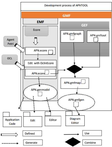
Fig.1. Development approach of the APNTOOL
-
A. Meta Modeling approach
-
a. The proposed Ecore Agent Petri Net Meta model
The fundamental step to develop the APN graphic editor is to specify a Meta model that allows expressing the structural concepts of this formalism as well as the relations between these concepts. The Ecore language is used to define the APN meta-model. Fig.2. (model diagram) presents the proposed meta-model "APN" in the universal modeling standard Ecore (tree representation).
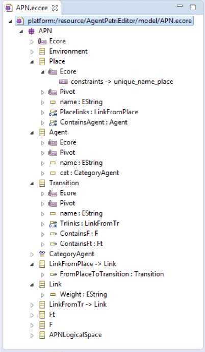
Fig.2. APN Meta model specifications in APN file.
The meta-model is defined by a set of EClasses as follows:
Place: This class represents the Petri Net Agent Model Places. Each place is characterized by a name (attribute name) and consists of Agent type tokens.
Agent: This class represents the Petri Net Agent template tokens where each agent is characterized by a name and has a category declared as an enumeration to limit their possible agent level values, which are moderator, nomoderator or Total moderator.
Transition: This class represents the transitions in the Agent Petri Nets system where each transition is characterized by a name and structurally comprises two functions: the relation function named f and an interaction relation named Ft. These two functions are themselves also Eclasses.
Link: This class models the arcs between the places and the transitions elements and is characterized by the weight of the arcs (attribute weight). Two subclasses inherit from this class: LinkFromPlace and LinkFromTr, which can be used to characterize an arc coming down from a place or a transition (this characterization is used to specify the upstream and the downstream of an arc).
F: This class describes the function of relation between the agents and expresses the possibility of an interaction between the agents. It is characterized by the syntax attribute, which is of type string, used to enter the code of the function.
Ft: This class describes the relationship between the agents and allows identifying the relations between two agents as well as the data to exchange during an interaction between the agents. It is also characterized by the syntax attribute, which is of type string used to enter the code of the relation.
Environment: This class represents a MAS environment. It is characterized by a name and contains all the components of the APN system: Places (Place), Transitions (Transition), Agent (Agent), Arcs (Link), the function of relationship between agents (F), relationship between agents (Ft) .The composition relation is modeled by the Ecore and Ereference concepts.
APNLogicalSpace: The presence of this class is due to the requirements of the implementation of the GMF Framework. It designs the workspace generated for the application (the space for instantiation and editing of model elements.). It contains the Environment element that represents the multi-agent system. An application can have only one environment or a set of sub-environments. In addition to its tree representation, EMF permits to visualize the APN Meta-model by a diagram, this representation is close to the UML class diagram (Fig.3.).
There are two possible uses of the "APN.ecore" model. On the one hand, the APN model can be used to define a specific application model that is based on the Agent Petri Net formalism. This is the case, for example, of our editor (See Fig4.a.). On the other hand, the model can be placed at a very high level of abstraction. It serves itself to define other models of the specific domain systems. The APN model is considered here as a meta-model, it describes Multi Agent system concepts: Agents (Agent Eclass), Environnent (Environnent Eclasse) and interaction between agents (Transition, F, Ft, and link: Eclasses). (See Fig4.b.).
-
b. The structural checking of the Meta model
The checking of a model's compliance with its metamodel is an essential key to validate a modeled system. The EMF Framework verifies a set of structural constraints. EMF guarantees the respect of the cardinality specification of Ereference between the model entities and still the respect of the senses of the relations (elements of the systems upstream and downstream of an arc). Another check concerns the case of deleting a referenced element, which automatically causes the deletion of all Ereferences (relations) related to this element. Nevertheless, EMF does not allow all to express and check all the constraints desired by the designer.
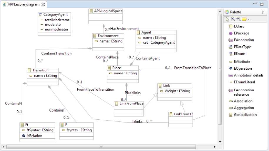
Fig.3. APNEcore Meta-model diagram
For example, the uniqueness of the names attributed to model instances is an essential constraint for a formal model such as Agent Petri Net where the negligence of this property causes ambiguities in understanding of the semantics of the models. A future simulation of models is an impossible task with the existence of semantic errors. We have enriched our APN model by adding the rules of uniqueness of the names of objects of the same class. The following constraints "unique_name_environment", "unique_name_place", "unique_name_transition" and "unique_name_agent" are defined for the classes Environment, Place, Transition and Agent respectively.
These constraints make it possible to formally ensuring that the name of each instance will be different from all the names of the other instances of the same class. As seen previously, Eclipse offers several possibilities to model the constraints. The choice of the OclinEcore constraints editor seems to be the most favorable. It offers the possibility of editing the Ecore model and adding the OCL constraints code in the Ecore APN.ecore metamodel. Fig.5. shows the model enriched by invariants.
In our modeling approach, the meta-model is extensible and an addition of other constraints is always possible.
|
Ecore as meta model |
Ecore as meta-meta model |
|
APN.ecore \?odel (Specific model) a |
APN. e core meTa model ( Generic model ) |
|
A real system eg: APNTool (Graphical Editor of APN) |
A model of specific domain eg: IntractionPtotocol. ecore |
|
/ |
A real System (egg Graphical Editor of a protocol) |
Describe
Fig.4. Ecore modeling levels.
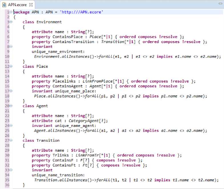
Fig.5. Meta-model enriched with OCL constraints code.
-
c. Generation of the application code
The EMF generates a basic tree editor that permits editing APN meta-model instances then uses this code. The APN generator model is stored in the file named "APN.genmodel". It is ready to be used to generate the application code (Code package). This code is then used to generate the edit code (Edit package) and the diagram code (package editor) of meta-model Agent Petri Net.
-
B. Generation of the graphic editor APNTOOL
In addition to the tree editor provided by the EMF Framework, GMF can generate a rich graphical editor that meets the needs of designers. The tool is obtained after a series of definitions of the graphical models, which serve to define a concrete representation and a model of connection, which serves to link the models (to make the necessary correspondence between them) and finally a generator model which serves to generate the code of the graphical editor (Diagram Editor). These models are detailed in this section. The following three tasks are necessary to generate the editor: to define the concrete representation of the elements of the models, to link the models and finally to generate the code of the diagrams.
-
a. Concrete Representation
This step can be summed up in the derivation of the graphic models and tools associated with the meta-model. We have proposed the concrete representation of the APN model elements.
Thus and as the generation of GMF models and especially the graphical model can often be inconvenient, a default figure is assigned to each element of the metamodel. GMF offers the possibility to the users to adapt it and to make the necessary modifications if needs. It provides a Gallery of available figures, so that the designers can develop personalized figure. For example, the default rectangle figure is assigned to all meta-model Eclasses and a link to the associations. In our proposal, we have edited all the representations of the figures elements of the graphical model generated. Fig.6. shows the graphical model.
For each element, we have specified a significant form that allows representing it graphically. After defining the graphical representation of the elements of our model, the definition of the tooling model is necessary. It provides a pallet of visual components corresponding to the elements of the meta-model. This pallet is used to instantiate and edit the elements of the model in the graphical editor. The generation of the tooling model is often suitable for the entire editor provided by GMF with, of course, the possibility of editing the model. We can keep the generated model unchanged. Fig.7. presents the tooling model APN.gmfTool that corresponds to the meta-model APN.Ecore.
j I® platformi/resource/AgentPetriEditor/model/APN.gmfgraph |
^ ^ Canvas APN
* -ф Figure Gallery Default
-
> ф Figure Descriptor Environ mentFigu re
-
> Ф Figure Descriptor PlaceFigure
-
> V Figure Descriptor TransitionFigure ------------ 1
-
> V Figure Descriptor LinkFromPlaceFigure
-
> ф Figure Descriptor LinkFromTrFigure
-
> Ф Figure Descriptor AgentFigure
-
> ф Figure Descriptor FtFigure
-
> ф Figure Descriptor FFigure
ф Node Environment (EnvironmentFigure)
-
•^ Node Place (PlaceFigure)
ф Node Transition (TransitionFigure)
ф Node Agent (AgentFigure)
^ Node Ft (FtFigure)
Ф Node F (FFigure)
ф Connection. LinkFromPlace
Ф Diagram Label EnvironmentName
Ф Diagram Label PlaceName
^ Diagram Label TransitionName
V Diagram Label LinkFromPlaceWeight
^ Diagram Label LinkFromTrWeight
-
-^ Diagram Label AgentName
^ Diagram Label FtFtSyntax
-
V Diagram Label FFsyntax
V Figure Descriptor TransitionFigure j v Scalable Polygon TransitionFigure
-
-ф- XY Layout
-
-ф Label TransionNameFigure
-
❖ №0)
^ (30,0)
^ (40,30)
(0,30)
^ (10,0)
< (30,0)
^ (35,15)
^ (5,15)
❖ (10,0)
-(- Child Access getFigureTransionNameFigure
-
Fig.6. Graphical model APN.gmfgraph.
-
b. Linkage of GMF models
GMF makes it possible to link the three models: the meta-model "APN.ecore", the graphical definition model "APN.gmfgraph" and the pallet definition model "APN. gmftooling" to obtain the binding model named "APN.gmfmap ". As we have already noted on the quality of the models generated by GMF, the link model is unsuitable. One must confirm the correspondence between the Ecore elements, the chosen graph and the appropriate pallet tool. All the three models must be selected correctly. Fig.8. shows the edited binding model.
-
c. The diagram code generation
At the end of this process and thanks to the GMF generation system, the java code of the Diagram Editor is obtained. The resulting file for this step is the "APN.gengmf". GMF uses this model to provide the implementation of the graphical editor. Our tool (APN) runs as an Eclipse plugin. Fig.9. shows the APN plugin interface. This tool permits the APN model elements editing from a palette of visual components on the workspace (APNLogicalSpace). A properties view is available to edit instantiated elements of the APN metamodel, for example for an Agent element, the values of its Name and Category attributes can be edited.
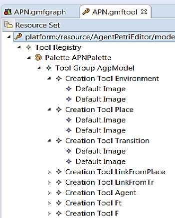
Fig.7. The APN.gmfTool tooling model
Towards a Meta-Modeling and Verification Approach of Multi-Agent Systems Based on the Agent Petri Net Formalism
Io Resource Set
-
4 © platform:/resource/AgentPetriEditor/model/APN,gmfmap
-
4 ^ Mapping
-
' fl Top Node Reference
-
4 fl Child Reference
p □ Node Mapping
-
4 fl Child Reference
-
4 □ Node Mapping
-
4 fl Child Reference
-
4 □ Node Mapping
sb Feature Label Mapping:[F.fsyntax:EString]
-
4 fl Child Reference
P □ Node Mapping
|
□ Properties й^ |
L |
|
Property |
Value |
|
\ 4 Domain meta information |
|
|
Containment Feature |
oc* Place.PlacelinkslinkFromPlace |
|
Element |
8 LinkFromPlace -> Link |
|
Source Feature |
|
|
Target Feature |
°* LinkFromPlace,FromPlaceToT... |
|
4 Mise |
|
|
Related Diagrams |
|
|
4 Visual representation |
|
|
Appearance Style |
|
|
Context Menu |
|
|
Diagram Link |
Connection LinkFromPlace |
|
Tool |
* Creation Tool LinkFromPlace |
J < Link Mapping
p
< Link Mapping
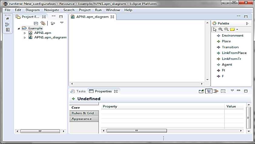
Fig.9. The APNtool plugin interface.
-
V. U se C ase
Today, parking system is a serious problem in the design of Smart Cities. Many studies proved that, when people are looking for a parking space they waste time, consume energy and they participate in the increase of the traffic congestion [36, 38]. The majority of research concerned with smart parking consider multi agents system as an efficient solution to resolve the problems of parking system like in [39, 40].
We experiment our APNTool in the design of a powerful Parking model, we release the idea in research [40], which assist user to find a parking place. According this research in [40], authors propose four agents to manage the parking system and each agent have specifics tasks to realize as follows:
o Driver Agent: researches a parking space by requesting a manager then waits for the manager’s answer (success or failure).
o Manager Agent: receives request from agents with their preferences (prices and location) and works to find the appropriate parking space according to the agents’ preferences by sending request to the Sector Agents.
o Sector Agent: works to find the appropriate
Parking agent’s space.
o Parking Space Agent: observes and validates the state of parking space and sends a result by message to Manager Agent.
Fig.10. presents a modeling of Parking System by APN formalism using our APNTool Editor. Where:
-
• DA, MA, SA1, SA2, SA3, PA1,PA2,PA3: set of
agents participate in parking management;
-
• P1: Driver Agent is ready to request;
-
• P2: Driver Agent is waiting to interact with
Manager Agent;
-
• P3: Driver Agent is waiting for Manager answer;
-
• P4: Manager Agent is ready to interact;
-
• P5: Manager Agent is preparing request to Sector
agent ;
-
• P6: Manager Agent is waiting for Sector Agent
answer ;
-
• P7: Sector Agents are ready to interact;
-
• P8: Sector Agents is preparing request to Parking
Space Agent ;
-
• P9: Sector Agents is waiting for Parking Space
Agent answer ;
-
• P10: Parking Space Agents are ready to interact;
-
• P11: Parking Space Agent is processing Sector
Agent request (success message or fail message or choose another Parking Space Agent) ;
-
• P12: Parking Space Agent is waiting to interact
with Manager Agent;
P13: Manager Agent is preparing Driver Agent answer;
P14: Manager Agent is waiting to interact with agent;
P15: Driver agent gets an answer of his request;
T1: Driver Agent sends request to Manager Agent with his preferences (place and price) ;
T2: Manager Agent receives Driver Agent request;
T3: Manager Agent sends requests to Sector Agent ;
T4: Sector Agent receives Manager Agent request;
T5: Sector Agent sends request to Parking Space Agent ;
T6: Parking Space Agent receives Sector Agent request ;
T7: Parking Space Agent chooses other Parking Space Sector;
T8: Parking Space Agent sends success message to Manager Agent;
T9: Parking Space Agent sends failure message to
Manager Agent;
T10:Manager Agent receives Parking Space Agent message;
T11: Manager Agent sends message to Driver Agent;
T12: Driver Agent receives Manager Agent message;
Fig.10. The APN Parking model edited with the APNTool.
U default?,apn £3 = в
*
_
< Placelinks We ight="MA" F romPla ceToTra n s it ion ="//@Ha s Environement.0/@Co nta in sTran s it ion - 3 "/>
Fig.11. The XML generated code of APN Parking model.
This act concerns the interaction between agents (DA, MA, SA, PA). Each agent sends request as a message to the concerned agent and crosses the appropriate transition T i . Driver Agent (DA) starts by requesting a parking space according to his preferences (place, price ), DA crosses transition T1. This schedule ends when Agent Driver receives the answer of his request by crossing transition T12.
In our contribution, the combination of formal method (APN) with Tools of Model driven Engineering in the design of our APNTool Editor, granted a height level of abstraction and rigour in the design of Parking Model. The structural verification of Parking Model is supported by integrating EMF with OCL. Once the model is edited, its XML specification is automatically generated. Fig.11. presents the serialized XML document of the example concerning Parking Model in the GMF runtime; due to limited space, just a snip of generating code is captured. This file is ready to be reused by the tool itself or by other tools in the mission of a semantic verification or simulation of Parking Model by analyses techniques of Petri Net. Thanks to its specification in the XML standard, which makes it possible to overcome interoperability problems between systems.
-
VI. C onclusion
In this paper, we proposed a meta-modeling approach based on the model Driven Architecture. A generic metamodel that describes the concepts of the Agent Petri Net formalism is developed by combining the formal APN language with the informal Ecore-EMF modeling approach. We have developed a graphical modeling tool called APNTool, which is used to graphically define specified models in APN formalism by exploiting the power of the EMF modeling platform and the generation platform of GMF graphic editors.
The advantages of this work can be summed up in two essential points: firstly, the combination of APN with EMF-Ecore, which introduces a great rigor into the modeling and increases the level of abstraction of the models. The resulting models of this combination are generic and extensible. Developers can reuse concepts implemented in this generic model to define their own specific models. Secondly, a system model edition tool in Agent Petri Net is developed following the MDA approach, which facilitates the creation of applications based on the models in the development processes. The tool is powerful and serves to define valid APN models thanks to the EMF and the enrichment that has been made by OCL constraints. This tool is extensible and adding features is possible at any time. In future works, we propose to add other functionalities to our APNTool such as the behavior check and the proposal of simulation models based on the universal representation of instances of APN models under XML.
References Towards a meta-modeling and verification approach of multi-agent systems based on the agent petri net formalism
- C.A. Petri, “Kommunication mit Automaten“ Ph.D. Thesis, Technischen Hoschule Darmstadt, 1962.
- V. Khomenko, O. H. Roux, (Eds) “Application and Theory of Petri Nets and Concurrency” LNCS, 10877, 2018. https://doi.org/10.1007/978-3-319-91268-4
- H. Hu, & M. Zhou, “A Petri net-based discrete-event control of automated manufacturing systems with assembly operations”. IEEE Transactions on Control Systems Technology, 23(2), 2015, pp. 513-524. https://doi.org/10.1109/TCST.2014.2342664
- S. Pujari, & S. Mukhopadhyay, “Petri net: A tool for modeling and analyze multi-agent oriented systems”. International Journal of Intelligent Systems and Applications (MECS Press), 4(10), 2012. doi: 10.5815/ijisa.2012.10.11
- Ding, Z., & Yang, R “Modeling and Analysis for Mobile Computing Systems Based on Petri Nets: A Survey”. IEEE Access, 6, 2018, 68038–68056. doi:10.1109/access.2018.2878807
- Q. Bai, M. Zhang, & K. T. Win, “A colored petri net-based approach for multi-agent interactions”. In Proc. of second International Conference on Autonomous Robots and Agents, Palmerston North, New Zealand, 2004, December, pp. 152-157.
- D. A. Zaitsev, & T. R. Shmeleva, “Modeling With Colored Petri Nets: Specification, Verification, and Performance Evaluation of Systems” In Automated Systems in the Aviation and Aerospace Industries, IGI Global, 2019, pp. 378-404. doi: 10.4018/978-1-5225-7709-6.ch014
- F. Pommereau, “SNAKES: a flexible high-level petri nets library” (tool paper). In International Conference on Applications and Theory of Petri Nets and Concurrency. Springer, Cham, 2015, June, pp. 254-265. https://doi.org/10.1007/978-3-319-19488-2_13
- S. Kerraoui, Y. Kissoum, M. Redjimi, M. Saker, “MATT: Multi Agents Testing Tool Based Nets within Nets”, Journal of Information and Organizational Sciences (JIOS), Vol 40, No 2, 2016, pp. 165-184. doi: 10.31341/jios.40.2.1
- L. W. Dworzanski and I. A. Lomazova, ‘‘Structural place invariants for analyzing the behavioral properties of nested petri nets,’’ in Application and Theory of Petri Nets and Concurrency. Cham, Switzerland: Springer, 2016, pp. 325–344. https://doi.org/10.1007/978-3-319-39086-4_19
- L. Chang, “A Nested Petri Net Framework for Modeling and Analyzing Multi-Agent Systems”. FIU Electronic Theses and Dissertations, 339, 2011. doi: 10.25148/etd.FI11040601. http://digitalcommons.fiu.edu/etd/339 accessed on 2019-04-12
- R. Valk, “Object petri nets”. Lecture notes in computer science, 3098, 2004, pp. 819-848. https://doi.org/10.1007/978-3-540-27755-2_23
- R. Kamdar, P. Paliwal, & Y. Kumar, “A State of Art Review on Various Aspects of Multi-Agent System”. Journal of Circuits, Systems and Computers, 27(11), 2018. doi: 10.1142/s0218126618300064
- J. R. Celaya, A. A. Desrochers and R. J. Graves, “Modeling and Analysis of Multi-agent Systems using Petri Nets”, Journal of Computers, October 2009. https://doi.org/10.1007/s10458-010-9146-1
- B. Marzougui, K. Hassine, & K. Barkaoui, “A new formalism for modeling a multi agent system: Agent petri nets”. Journal of Software Engineering and Applications, 3(12), 2010. https://doi.org/10.1007/978-3-642-36285-9_54
- D. C. Schmidt, “Model-driven engineering”. computer-ieee computer society-, 39(2), 2006. doi: 10.1109/MC.2006.58
- C. Atkinson, T. Kühne, “Model-driven development: a metamodeling foundation”. IEEE software, 20(5), 2003, pp. 36-41. doi: 10.1109/MS.2003.1231149
- A. Rodrigues da Silva, Model-driven engineering: A survey supported by the unified conceptual model. Computer Languages, Systems & Structures, 43, 2015, pp.139–155.doi:10.1016/j.cl.2015.06.001
- C. Sansores, & J. Pavón, “Agent-Based Simulation Replication: A Model Driven Architecture Approach”. MICAI 2005: Advances in Artificial Intelligence, 2005, pp. 244–253. doi:10.1007/11579427_25
- Eclipse, http://www.eclipse.org accessed on 2019-03-12
- GMF, https://www.eclipse.org/modeling/gmp/ accessed on 2019-03-12
- Eclipse Foundation, Inc: The Eclipse Modeling Framework (EMF), 2019. https://www.eclipse.org/modeling/emf/ accessed on 2019 03-12
- Eclipse-ocl. http://download.eclipse.org/ocl/doc/6.3.0/ocl.pdf accessed on 2019-03-12
- Object management group: object constraint language, Formal specification OCL. https://www.omg.org/spec/OCL/2.4/ accessed on 2019-03-12
- M. Borhen, K. Barkaoui, & N. H. Alouane, “APN Model for Specification of the Communication Protocols in Multi-Agent System”. Journal of Software Engineering and Applications, 6(09), 2013. doi: 10.4236/jsea.2013.69A002
- B. Marzougui, K. Hassine, K. Barkaoui. "Modeling Migration of Mobile Agents", Lecture Notes in Business Information Processing- Springer, vol.132, 2013, pp.530-540, doi:10.1007/978-3-642-36285-9_54
- FIPA, Foundation for Intelligent Physical Agents http://www.fipa.org/ accessed on 2019-03-21
- B. Marzougui, K. Barkaoui. "Agent Petri Nets Framework for Modeling Staphylococcus epidermidis Biofilm Formation", E-Health Telecommunication Systems and Networks (ETSN), vol.5(1), 2016, pp.19-30. doi:10.4236/etsn.2016.51003
- CPNL http://cpntools.org/ accessed on 2019-03-21
- The Reference Net Workshop http://www.renew.de/ accessed on 2019-03-12
- E. Gamma and k, Beck, “Contribution To Eclipse Principles, patterns, plugin”. Addison-Wesley Professional, first edition, October 30, 2003. ISBN-13: 978-0321205759
- E. Biermann, K. Ehrig, C. Ermel, J. Hurrelmann, “Generation of simulation views for domain specific modeling languages based on the Eclipse modeling framework”. In: 2009 IEEE/ACM International Conference on Automated Software Engineering, 2009, pp. 625–629, https://doi.org/10.1109/ASE.2009.46
- W. Moore, D. Dean, A. Gerber, G. Wagenknecht, & P. Vanderheyden. Eclipse Development using the Graphical Editing Framework and the Eclipse Modeling Framework. IBM Redbooks, 2004. ISBN 0738453161
- D. Steinberg, F. Budinsky, & M., E. Merks “EMF: Eclipse Modeling Framework. Eclipse”, Addison Wesley Professional, 2009, ISBN 9780321331885.
- Eclipse Foundation, Inc: The Eclipse Graphical Editing Framework (GEF), 2019. https://www.eclipse.org/gef/, accessed on 2019-03- 12
- R. Arnott, T. Rave, & R. Schöb, “Alleviating urban traffic congestion”. MIT Press Books, number 0262012197, 2005.
- A. Koster, F. Koch, & A. L. Bazzan, “Incentivising crowdsourced parking solutions”. In International Workshop on Citizen in Sensor Networks, Springer, Cham. 2013, September, pp. 36-43. doi:10.1007/978-3-319-04178-0_4
- D. Shoup, “The high cost of free parking”. A Planners Press Book, Taylor & Francis Group, New York, 2017. https://doi.org/10.4324/9781351179782
- L. F. S. Castro, G. V. Alves, & A.P. Borges, “Using trust degree for agents in order to assign spots in a Smart Parking”. Advances in Distributed Computing and Artificial Intelligence Journal, 6(2), 2017, pp. 45-55. DOI: http://dx.doi.org/10.14201/ADCAIJ2017624555
- L. F. S. Castro, G. V. Alves, & A.P Borges “Developing a smart parking solution based on a Holonic Multiagent System using JaCaMo Framework”. In Anais do XII Workshop-Escola de Sistemas de Agentes, seus Ambientes e apliCações - WESAAC 2018, volume XII, pages 226–231, Fortaleza, CE, 2018.
