Tracking Power Photovoltaic System using Artificial Neural Network Control Strategy
Author: M.T. Makhloufi, M.S. Khireddine, Y. Abdessemed, A. Boutarfa
Journal: International Journal of Intelligent Systems and Applications(IJISA) @ijisa
Article in issue: 12 vol.6, 2014.
Free access
Photovoltaic generation is the technique which uses photovoltaic cell to convert solar energy to electric energy. Nowadays, PV generation is developing increasingly fast as a renewable energy source. However, the disadvantage is that PV generation is intermittent because it depends considerably on weather conditions. This paper proposes an intelligent control method for the maximum power point tracking (MPPT) of a photovoltaic system under variable temperature and solar irradiation conditions. In this paper, a simulation study of the maximum power point tracking (MPPT) for a photovoltaic system using an artificial neural network is presented. The system simulation is elaborated by combining the models established of solar PV module and a DC/DC Boost converter. Finally performance comparison between artificial neural network controller and Perturb and Observe method has been carried out which has shown the effectiveness of artificial neural networks controller to draw much energy and fast response against change in working conditions.
Solar Energy, Photovoltaic, MPPT, P&O, Boost Converter, Artificial Neural Network
Short address: https://sciup.org/15010633
IDR: 15010633
Text of the scientific article Tracking Power Photovoltaic System using Artificial Neural Network Control Strategy
Published Online November 2014 in MECS
Significant progress has been made over the last few years in the research and development of renewable energy systems such as wind, sea wave and solar energy systems. Among these resources, solar energy is considered nowadays as one of the most reliable, daily available, and environment friendly renewable energy source [1-2].
However, solar energy systems generally suffer from their low efficiencies and high costs [3]. In order to overcome these drawbacks, maximum power should be extracted from the PV panel using MPPT techniques to optimize the efficiency of overall PV system. MPPT is a real-time control scheme applied to the PV power converter in order to extract the maximum power possible from the PV panel [12].
The MPPT working principle is based on the maximum power transfer theory. The power delivered from the source to the load is maximized when the input resistance seen by the source matches the source resistance.
In this paper, an intelligent control technique using artificial neural network control is associated to an MPPT controller in order to improve energy conversion efficiency.
The circuit diagram of the energy conversion system is shown in Fig.1. The system consists of photovoltaic panel, a DC/DC boost converter, a control unit and a resistive load. The first stage of the system is solar panel. The I-V characteristic of a panel depends on the temperature and solar irradiance. The three most important characteristics of PV panel are the short circuit current, open circuit voltage and the MPP which is a function of panel temperature and solar irradiance. The power stage is the well known Boost converter witch duty cycle is regularly adjusted to track the maximum power point that can be delivered by the PV panel. The proposed MPP tracker, which is based on artificial neural networks control, has the objective to draw as much power as possible from the PV module by adjusting continuously the duty cycle of the DC/DC converter. This point corresponds to the maximum power point (MPP) on the PV curve.
Pv module
Boost
Converter
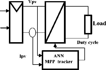
Fig. 1. Schematic diagram of the proposed power conversion PV array
-
II. PV Array
Photovoltaic cell is the most basic generation part in PV system. Single-diode mathematic model is applicable to simulate silicon photovoltaic cells, which consists of a photocurrent source I ph , a nonlinear diode, internal resistances R s and R sh , as shown in Fig.2.
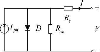
Fig. 2. Single-diode mathematic model of a PV cell
The mathematic relationship for the current and voltage in the single-diode equivalent circuit can be described as q ( v+IRs)
I = I ph - I s ( e AkT
- 1) -
V + IR s
R sh
where, I ph is photocurrent; I s is diode saturation current; q is coulomb constant (1.602e-19 C ); k is Boltzman’s constant (1.381e-23 J/K ); T is cell temperature ( K ); A is P-N junction ideality factor; R s and R sh are intrinsic series resistances.
Photocurrent is the function of solar radiation and cell temperature described as
' S
I ph = [ I phref + C t (T - Tref ) ] (2)
к Sref J where, S is the real solar radiation (W/m2); Sref , Tref , Iph,ref is the solar radiation, cell absolute temperature, photocurrent in standard test conditions respectively; CT is the temperature coefficient (A/K).
Diode saturation current varies with the cell temperature
I = I f s s,ref
I T
T к T r e f J
e
where, Is,re f is the diode saturation current in standard test conditions ; E g is the band-gap energy of the cell semiconductor (eV) , depending on the cell material.
When PV cells are arranged together in series and parallel to form arrays. These cells are usually considered to have the same characteristics. The equivalent circuit of PV array can be described as Fig.3.
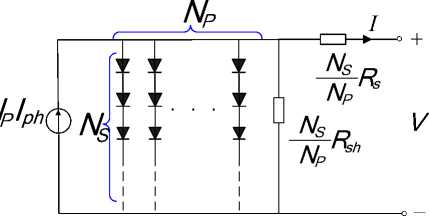
Fig. 3. Single-diode mathematic model of a PV array
The relationship of the voltage and current in PV array is:
I = N p I h - N p I s ( e ATV+N P ) — 1) — N^< V + R ) (4)
Rsh NS NP
Where, NS and NP are cell numbers of the series and parallel cells respectively.
We have used the MATLAB/Simulink software in order to implement the model of the PV array, as shown in Fig. 4.
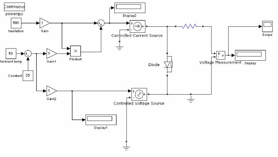
Fig. 4. Simulink model of the solar PV module
Considering different temperatures and solar irradiations, the simulated output characteristics of the PV array are depicted in Fig. 5 and Fig.6.
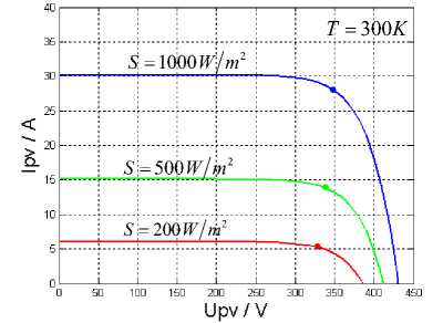
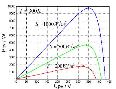
Fig. 5. Characteristic curves of the PV array with different solar irradiations
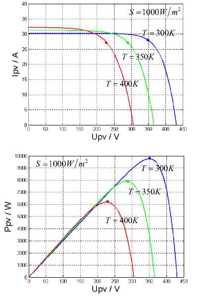
Fig. 6. Characteristic curves of the PV array with different cell temperatures.
As shown in Fig.4 and Fig.5, the PV array has nonlinear voltage-current characteristics, and there is only one unique operating point, the MPP, for a PV generation system with a maximum output power under a particular environmental condition.
-
III. Maximum Power Point Tracking
A dynamic tracking method is necessary to extract the maximum power from the PV cells [3]. Many researches has been developed concerning the different algorithms for the maximum power point tracking (MPPT) considering the variations of the system parameters and/or weather changes, such as perturb and observe method, open and short circuit method, incremental conductance algorithm, fuzzy logic and artificial neural network. The block diagram in Fig.2 presents a PV generator with MPPT [5]. The load or the battery can be charged from a PV panel using a MPPT circuit with a specific controller to track the peak power generated by the PV panel.
Other protection devices can be added. The control circuit takes voltage and current feedback from the battery, and generates the duty cycle D. This latter defines the output voltage of the Boost converter.
Many MPTT control techniques have been conceived for this purpose these last decades [10]. They can be classified as:
-
• Voltage feedback based methods which compare the PV operating voltage with a reference voltage in order to generate the PWM control signal of the DC/DC converter [8].
-
• Current feedback based methods which use the PV module short circuit current as a feedback in order to estimate the optimal current corresponding to the maximum power.
-
• Power based methods which are based on iterative algorithms to track continuously the MPP through the current and voltage measurement of the PV module. In this category, one of the most successful used method is perturbation and observation (P&O) technique.
-
IV. DC/DC Converter Modelling
Fig.7 shows the electrical circuit of a boost converter. The power switch ‘S’ is used to modulate the energy transfer from the input source to the load by varying the duty cycle D [6]. The relationship between input and output voltages of boost converter operating at steady state condition is given by:
-
V 0 = 1 (5)
-
V 1 - D
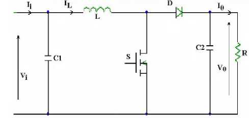
Fig. 7. Boost converter circuit
The control strategy lies in the manipulation of the duty cycle of the switch which causes the voltage change.
When the switch is closed and the inductor is charged by the source through the switch. The charging current is exponential in nature but for simplicity is assumed to be linearly varying. The diode restricts the flow of current from the source to the load and the demand of the load is met by the discharging of the capacitor. When the switch is open and the diode is forward biased. The inductor now discharges and together with the source charges the capacitor and meets the load demands. The load current variation is very small and in many cases is assumed constant throughout the operation.
The MATLAB/Simulink model of the basic boost converter is shown in Fig.8.
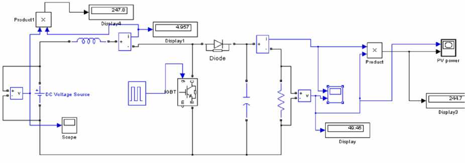
Fig. 8. Simulink model of boost converter.
-
V. Different Algorithm Mppt
It is necessary to constantly track the MPP of a solar panel. For the past years, research has focused on various
MPP control algorithms to draw the maximum power of the solar array. In this section, the effectiveness of two different control algorithms are thoroughly investigated using a numerical simulation.
-
A. P&O controller method
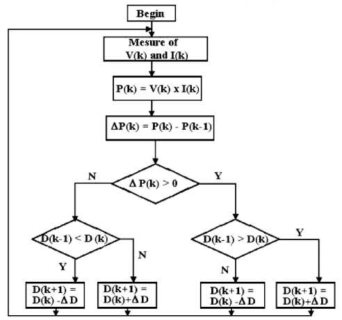
is increased to reach the MPP [8].
-
B. Artificial Neural Network controller method
required optimal duty cycle ‘D’. Even with sparse data in a multidimensional measurement space, the algorithm provides smooth transitions from one estimated value of D to another. The ANN consists of an input layer (Ppv), a pattern layer, a summation layer an output layer. The output of the ANN is the duty cycle D(x) as follow:
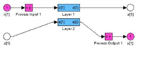
Fig. 11. The Simulink used artificial neural network model
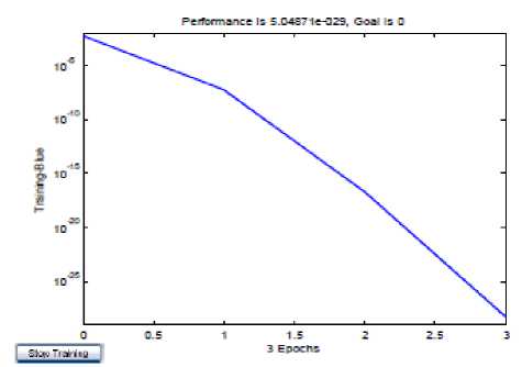
Fig .12. Training error using the neural network for learning, the obtained error is very small about 10.0e-25
The MPPT technique proposed differs from other techniques in that the duty cycle of the switching of the DC/DC boost converter is optimally calculated on-line. The algorithm of the three-point weights comparison is run periodically by perturbing the solar array terminal voltage and comparing the PV output power on three points of the P-V curve. The three points are the current operation point (A), a point B, perturbed from point A, and a point C, with doubly perturbed in the opposite direction from point B. Fig.13 depicts the three possible cases. In these cases, for the points A and B, if the power corresponding to the point B is greater than or equal to that of point A, the status is assigned a positive weighting. Otherwise, the status is assigned a negative weighting. Amongst the three measured points, if two are positively weighted, the duty cycle of the converter should be increased. On the contrary, when two are negatively weighted, the duty cycle of the converter should be decreased. In the other cases with one positive and one negative weighting, the MPP is reached or the solar radiation has changed rapidly and the duty cycle must not be changed. Fig.13 shows the idea of the MPP detection algorithm.
They are maintained constants in stable working conditions.
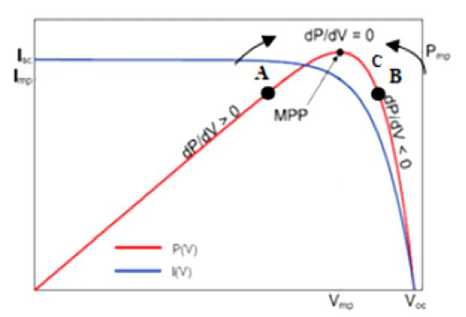
Fig.13. Sign of dP/dV at different positions on the power Characteristic of a PV module.
-
VI. Simulation Results
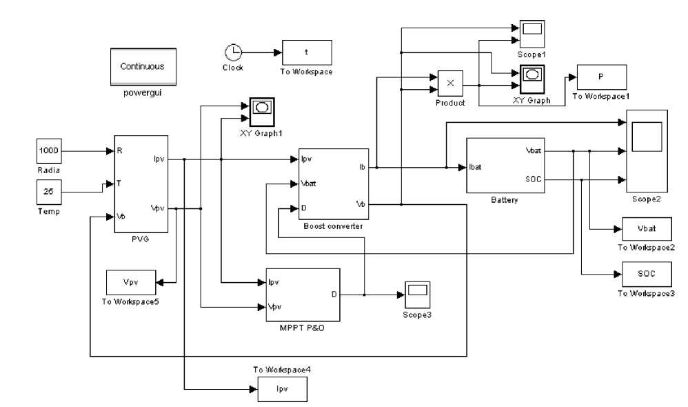
Fig.14 shows the overall simulation circuit under MATLAB/Simulink In order to validate the on-line learning ANN, many simulations tests have been implemented.
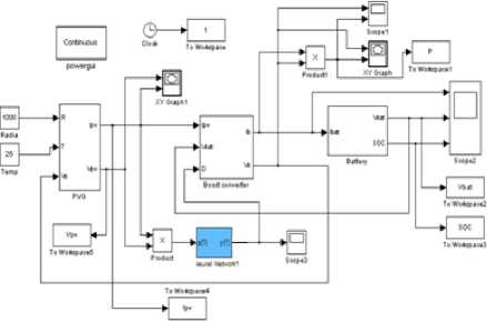
Fig. 14. Simulink model for ANN Alghorithm
-
A. Operation in standard environmental conditions
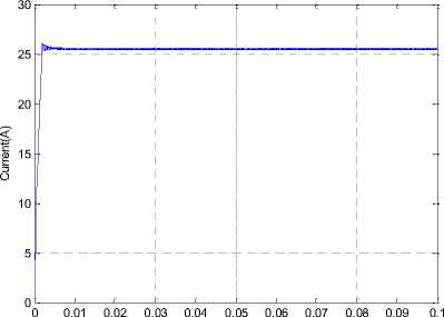
The Figs. 15, 16 and 17 below allow us to visualize the output PV panel current, voltage and power using the fuzzy controllers in standard atmospheric conditions (1000W/m2, 25°C).
Ipv
Time(sec)
Fig.15. The output PV panel current
Time(sec)
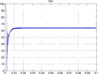
Fig.16. The output PV panel voltage
Ppv
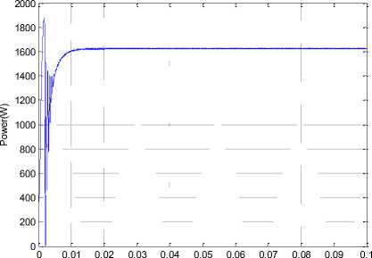
Time(sec)
Fig. 17. The output PV panel power
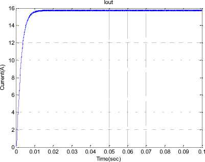
Fig. 21. The Boost converter output current with ANN controller
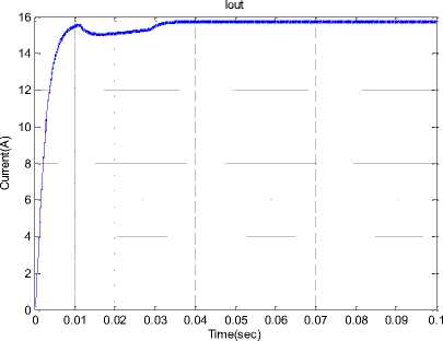
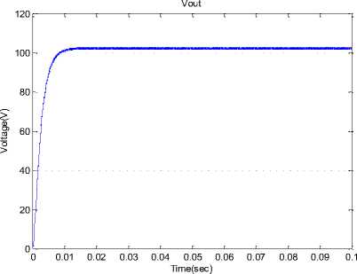
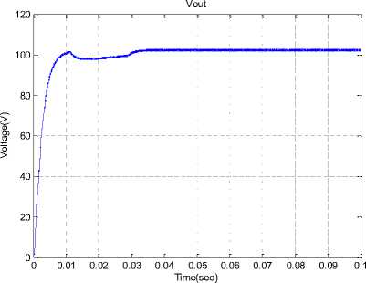
Fig. 22. The Boost converter output voltage with The ANN controller
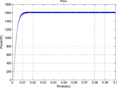
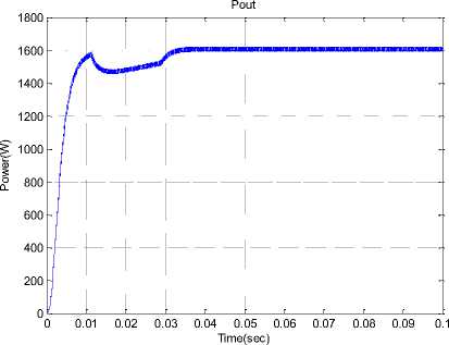
Fig.23. The Boost converter output power with ANN controller
-
B. Operation in variable solar radiation conditions
To visualize the behavior of our system in real conditions, we vary the irradiation as the increment step. These variations allow us to study the robustness of our system using ANN controller.

Fig. 24. The duty cycle ‘D’ variation
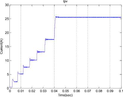
Fig. 27. The Boost converter output current with a step change of irradiance with ANN controller
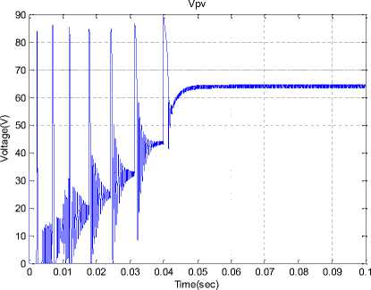
Fig. 28. The Boost converter output voltage with a step change of solar irradiance with ANN controller
Fig. 25. The output battery voltage during the charging period
SOC
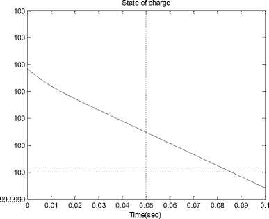
Fig. 26. The state of charge of the battery ‘SOC’ using the ANN controller
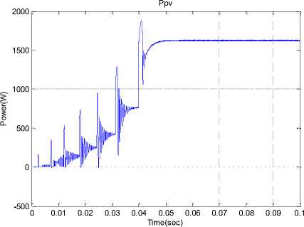
Fig. 29. The Boost converter output Power with a step change of solar irradiance with ANN controller
The simulation results illustrated in Figs. 27, 28 and 29 confirm that the ANN controller has good performance response such as rapidity and damping of the overshoot when the solar radiation decreases rapidly due to sudden shading for example during eclipses, considering that the PV temperature is kept constant at 25°C throughout the simulation time interval (0.1 sec.).
-
VII. Conclusion
We conclude that MPPT ANN controller, which is initially based on the experience of the operator during the training stage, has a very good transient performance. It improves the responses of the photovoltaic system: not only it reduces the time response to the track the maximum power point but it also eliminates the fluctuations around this point. This proves the effectiveness of the ANN control for photovoltaic systems under varying environmental conditions. The results obtained for this energy conversion system, show that by using the MPPT ANN controller, there is a compromise between rapidity in transient regime and stability in steady state. These controller results can be compared to other methods of control as using neural networks in optimizing the photovoltaic generator power. The idea of our future research work would be the use of a hybrid fuzzy-neural controller in order to better the PV system static and dynamic performances.
References Tracking Power Photovoltaic System using Artificial Neural Network Control Strategy
- C.L.B. Wu and R. Cheung. “Advanced algorithm for MPPT control of photovoltaic systems”. Canadian Solar Buildings Conference, Montreal, 2004.
- E.I. Rivera. “Maximum Power Point Tracking using the Optimal Duty Ratio for DC-DC Converters and Load Matching in Photovoltaic Applications”. IEEE, pp. 987-991, 2008.
- J.A. Jiang, T.L. Huang, Y.T. Hsiao, and C.H. Chen Tamkangn. “Maximum Power Tracking for Photovoltaic Power Systems”. Journal of Science and Engineering, Vol. 8, No 2, pp. 147-153, 2005.
- M.A. Elgendy, B. Zahawi, and D.J. Atkinson. “Assessment of Perturb and Observe MPPT algorithm implementation techniques for PV pumping applications”. IEEE transactions on sustainable energy, pp.21-33, Vol 3, No 1, 2012.
- N. Femia, G. Petrone, Giovanni Spagnuolo, and Massimo Vitelli. “ Optimization of Perturb and Observe Maximum Power Point Tracking Method”. Transactions on power electronics, pp.963-973, Vol 20, No 4, 2005.
- T. Hiyama, S. Kouzuma, and T. Imakubo. “Evaluation of neural network based real time maximum power tracking controller for PV system”. IEEE Trans. Energy Conversion, vol. 10, pp. 543-548,1995b.
- T.N. Tamer, A. Khatib, N. Mohamed, and K. Amin. “An Efficient Maximum Power Point Tracking Controller for Photovoltaic Systems Using New Boost Converter Design and Improved Control Algorithm". WSEAS Transactions on power systems, April 2010, Issue 2, Vol. 5, pp. 53-60.
- M. Veerachary, T. Senjyu, and K. Uezato. “Neural Network Based Maximum Power Point Tracking of Coupled Inductor Interleaved Boost Converter Supplied PV System using Fuzzy Controller”. IEEE Transactions on Industrial Electronics, Vol. 50, No. 4, pp. 749-758, August 2003.
- G. Bin, D. Jason, J.S. Lai, Z. Zheng, and L. Chung. “High boost ratio hybrid transformer DC-DC converter for photovoltaic module applications”. IEEE Trans. Power Electron. 28, 2048–2058, 2013.
- K.C. Tseng, C.C. Huang, and W.Y. Shih. “A high stepup converter with a voltage multiplier module for a photovoltaic system”. IEEE Trans. Power Electron. 2013, 28, 3047–3057.
- H.H. Lee, L.M. Phuong, P.Q. Dzung, N.T. Dan Vu, and L.D. Khoa. “The new maximum power point tracking algorithm using ANN-based solar PV systems”. Proceedings of the IEEE Region 10 Conference (TENCON '10), pp. 2179–2184, Fukuoka, Japan, November 2010.
- S. Daison Stallon, K. Vinoth Kumar, S. Suresh Kumar, and Justin Baby. “Simulation of High Step-Up DC–DC Converter for Photovoltaic Module Application using MATLAB /SIMULINK”. IJISA International Journal of Intelligent Systems and Applications. pp. 72-82, Vol 7, No 10, 2013.
- R. De Keyser, J. Bonilla, and C. Ionescu. “A Comparative Study of Several Control Techniques Applied to a Boost Converter”. IEEE 10th Int Conf on Optimisation of Electrical and Electronic Equipment OPTIM, Brasov Romania, 71-78,ISBN 973-635-704-X, (Eds. Cernat, Nicolaide, Margineanu), 2006.
- D. Vasarevicius, R. Martavicius, and Pikutis M. “Application of Artificial Neural Networks for Maximum Power Point Tracking of Photovoltaic Panels”. Elektronika ir Elektrotechnika, ISSN 1392-1215, Vol. 18, N° 10, 2012.
- M.A. Younis, T. Khatib, M. Najeeb, and M. Ariffin. “An Improved Maximum Power Point Tracking Controller for PV Systems Using Artificial Neural Network”. PRZEGLĄD ELEKTROTECHNICZNY (Electrical Review), pp.116–121, 2012.
- B. Amrouche B, Belhamel M, Guessoum “A. Artificial intelligence based P&O MPPT method for photovoltaic systems [R]”. Revue des Energies Renouvelables (ICRESD-07), Tlemcen (2007), pp.11–16.
