Traditional PI and FPIL based VFCU for an isolated induction generator (IIG)
")
Author: Shakuntla Boora, S.K. Agarwal, K.S. Sandhu
Journal: International Journal of Intelligent Systems and Applications @ijisa
Article in issue: 12 vol.9, 2017.
Free access
With the increase in load, the AC terminal voltage and frequency at the consumer premises decreases. Hence, there is encountered a need of some simple and intelligent controller which can support both voltage and frequency under load conditions. This manuscript emphasis on implementation and testing of traditional PI and non- traditional fuzzy PI logic (FPIL) based voltage and frequency controller unit (VFCU) in MATLAB based SIMULINK environment for an IIG for step change in consumer load. The electronic Controller comprises of various elements: a 3-leg diode bridge rectifier, chopper as a switch, dc filtering capacitor, discrete PI controller block, fuzzy logic controller block, and a resistive type dump load. The transient and the steady state behavior of IIG-VFCU system is examined and tested under different operating conditions to illustrate the efficaciousness of intelligent controller as compared to traditional PI controller. The performance enhancement of IIG is attained relating to rise time, settling time, overshoot and THD values using the planned intelligent controller.
Isolated Induction Generator (IIG), static loads, diode bridge rectifier, MATLAB /SIMULINK, THD, fuzzy logic
Short address: https://sciup.org/15016440
IDR: 15016440 | DOI: 10.5815/ijisa.2017.12.02
Text of the scientific article Traditional PI and FPIL based VFCU for an isolated induction generator (IIG)
Published Online December 2017 in MECS
Distributed or ON-site power generation has proven to be more reliable and economical in recent years than the OFF-site generation due to its cost, complexity of national grid system, reduced reliability and transmission losses. Thus, a distributed power generation system is an alternative or an enhancement of the existing traditional electric power system. Thus a suitable and feasible independent isolated system using regionally obtainable energy sources like small hydro, wind, biomass become a preferred option. As these energy sources systems are attainable in far-off areas they must be reliable, sturdy, cost effective and manageable by regional communities.
The unskilled community must handle the complete system comprises of prime mover, ac generator and its related controller. The Isolated Induction generator (IIG) is the most preferred and suitable option due to single excitation, cost effective, simple construction, ruggedness, brushless rotor, requires little or no maintenance, selfprotection under short-circuit conditions and its off-the shelf availability. Due to the latest research on non conventional energy sources and grid OFF systems, the IIG becomes one of the most important and favoured renewable sources of energy [1-14]. For power rating below 100kW, uncontrolled turbines driving IIG are recommended. These turbines keep the hydropower potential constant and hence solicit the IIG output power to be retain constant at different operating conditions of consumer loads. This necessitates, a VFCU where a complementary nature load is connected in shunt or across the consumer load so that the total active power consumed is retain constant.
In this paper, first time an initiative is taken to adjudge the performance of an IIG using both PI and FPIL based controller to support both voltage and frequency under balanced and unbalanced load operating conditions. Fuzzy logic based mamdani type approach is discussed and implemented in this manuscript because such controller can handle non-linearity and also do not require mathematical model of the system.
The whole manuscript is organized as follows: Section II covers the related work. Overview about the Simulink model of the IIG and VFCU is covered in section III. Section IV introduces about the traditional PI and FPIL based control techniques. The simulated outcomes of the traditional PI and FPIL based controller are discussed, interpreted and compared in section V. Finally, the various simulated outcomes are concluded in section VI.
-
II. Related Work
Various types of voltage and frequency controllers (VFC’s) for IIG have been developed and are reported in literature along-with its advantages and disadvantages [414]. The IIG can be used for constant power applications and for variable power applications. In constant power applications, prime mover rotational speed, value of excitation capacitor and the consumer load are kept constant and thus known as a single point operation. For variable power applications, rotation of the prime mover is kept fixed but the value of excitation capacitance increases with load. For constant power application, generated power and consumer output power must be fixed for stable operation of three-phase IIG. Input power is maintained constant with the help of uncontrolled picohydro turbine but power output may not be constant due to varying consumer load. Most of the VFC’s reported in literature employed traditional PI type controllers because of their simple design. The major drawback was in attaining the optimal performance. But, today different types of intelligent controllers are grabbing the attention of researcher [15-17]. These controllers efficiently handles system non-linearity, noisy signals and provides better performance of the system in terms of rise time, settling time etc.
-
III. Overview about the Simulink Model of the IIG and Vfcu
The complete simulink model of the three-phase VFCU-IIG system is depicted in Fig. 1. The whole system is a build by integrating various elements: Induction machine, delta connected capacitor bank, three-phase load and VFCU. First, a delta connected capacitor bank is connected across the stator terminals of the machine to generate the rated voltage at no load then the induction machine is run above the synchronous speed of the motor with the help dc machine[appendix A]. Now, the induction machine starts operating as an Isolated Induction Generator (IIG) The IIG is simulated in stationary reference frame and the effect of saturation is also included. The complete data of the machine along-with the saturation characteristics is provided in appendix A.
Then a three-phase balanced load is connected to the IIG terminals with the help of circuit breakers. Due to this load, there is reduction or dip in the voltage generated by the IIG. This IIG voltage needs to be boosted up for the satisfactory operation of the devices. This boost in voltage during load conditions is provided by VFCU with the help of traditional PI and FPIL based control criteria discussed in section IV. This VFCU basically consists of various components: six-pulse diode bridge rectifier, an IGBT type high frequency (1 kHz) operated chopper switch, a filtering capacitor (C), a complementary load resistance (Rdld). The diode based bridge rectifier provides dc output voltage. The output dc voltage has the distortion, which should be filtered and therefore a capacitor filter is used to smoothen the dc output voltage. An IGBT type high frequency chopper switch provides the variable dc voltage across the Rdld. Initially the consumer load and the VFCU are kept OFF and the IIG is self-excited at no-load. After successful voltage build-up of 650 V, the VFCU consumes the whole of the generated power. When both the consumer load and the chopper is switched ON, the current flows through the Rdld and consumes the difference between the generated power and consumer load power and thus result in a constant load on the IIG and hence constant voltage and frequency at the balanced/unbalanced consumer load. Thus the IIG retains the power balance in the system.
For the proper operation of IIG, the suitable value of capacitors is connected to generate rated voltage at desired power [5-14].The input power of the IIG is held constant at varying consumer loads. Thus, IIG supplies power to both the consumer load and R dld in shunt. When one load is consuming more power than the other load will be consuming less power so that the total power is constant. It means both loads are complementary in nature. The power balance is maintained in the system with the help of VFCU. The power balance equation for the IIG system is written as
Plig d d I d + Pel d (1)
Where, P iig is the power generated by the IIG. P cld is the consumer load power and P dld is the dump load power to be dumped in dump load resistance R dld. The dump load power (Pdld) may be used for various applications like lighting loads, water heating, water pumping, charging of batteries, cooking, fire purpose, baking, space heating, heating elements etc. In this way, power generated by IIG is utilised in a better and efficient way. Thus, makes the whole generating system more efficient and reliable.
-
IV. Control Techniques
-
A. Design of traditional PI Controller
The control circuit of VFCU is based upon calculation of the magnitude of the three-phase terminal ac voltage of IIG given by
Vter = ( I ( Vas + abs + ^s )}2 (2)
This voltage is then compared with the ac reference voltage of 650V. The output of this comparator is the error voltage and its expression is given by
^ a c ^t erf ^t er (3)
This error in ac voltage is then processed through a discrete PI controller. The output of the PI controller is given by
-
(x) = ((x— 1) + ^pac^eacCx) Vee(C^x_ i)} + К[асУеас(х)
Where Veac signifies the error in terminal ac voltage in (3) and I(X) signifies the output control signal at the xth time. I(x-1) signify the output control signal at the (x-1)th time. Kpac and Kiac are the proportional and integral gains of the discrete PI controller. The output of the PI controller is now compared with the saw tooth type high frequency waveform (1 kHz) to generate Pulse width modulated gate driving signal of varying duty cycle for the chopper switch [Fig. 1]. The optimised or properly tuned values of Kpac and Kiac to obtain better performance under both steady and transient conditions are provided in appendix A.
-
B. Design of FPIL Approach Based Controller
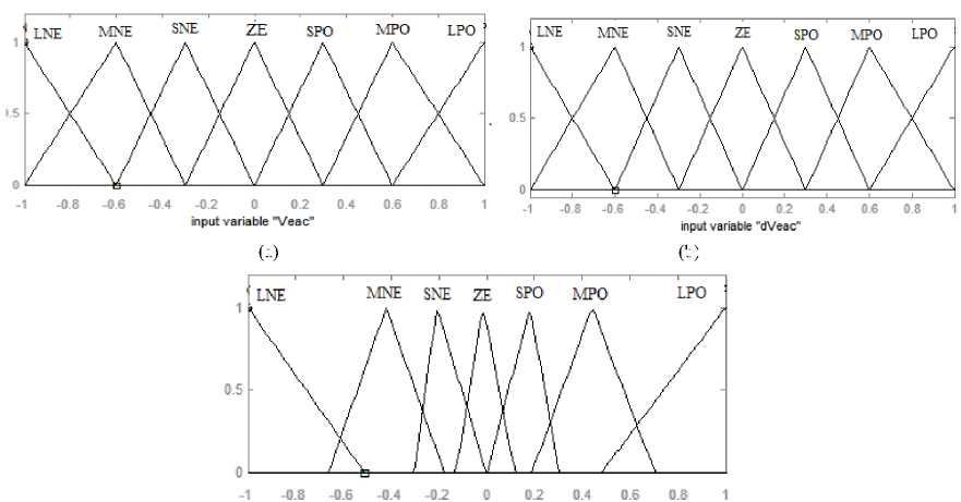
In order to obtain better results pertaining to performance, the PI controller is replaced by a fuzzy logic controller block. In this research paper, Mamdani Type FPIL a.c terminal voltage controller is developed [Fig. 2]. The FPIL approach based controller consists of four processes or stages: fuzzification process, rule base, fuzzy interface link and defuzzification process. The fuzzification process is required for the conversion numerical input variable to a linguistic variable. The fuzzy interface link consists of simple input-output relationship. Input data is managed by FI link to produce output data using Mamdani type fuzzy interface algorithim. The defuzzification process converts the fuzzy set output into a crisp value. The centre of area method is used for this process. In table 1, LNE, MNE, SNE, ZE, SPO, MPO, LPO are considered as large negative large, medium negative, small negative, zero, small positive, medium positive and large positive. The 49 rules are formed using If – then rules and are given in table 1. The variable error voltage Veac and change in error voltage dVeac signifies the inputs of FPIL approach based controller. The seven triangular membership functions are used for Veac, dVeac and output variable I(x) [Fig. 4]. The variation range for the fuzzy variable i.e. Veac, dVeac and I(x) is kept from -1 to 1 only. This needs scaling of both input and output variables within the specified range. Thus, the scaling factors for the variables Veac, dVeac and I(x) are 0.012, 0.001 and 0.29 respectively.
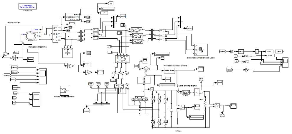
Fig.1. Simulink model of the generating unit along with VFCU for terminal ac voltage (V ter ) control using traditional PI
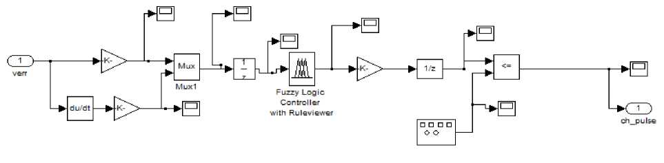
Fig.2. Magnitude of terminal ac voltage (Vter) control using FPIL based criteria.
Table 1. Rules defining relationship between inputs and output
|
V eac dV eac |
LNE |
MNE |
SNE |
ZE |
SPO |
MPO |
LPO |
|
LNE |
LNE |
LNE |
MNE |
SPO |
SPO |
MPO |
MPO |
|
MNE |
LNE |
MNE |
MNE |
SPO |
SPO |
MPO |
MPO |
|
SNE |
MNE |
MNE |
SNE |
MPO |
SPO |
ZE |
MPO |
|
ZE |
MNE |
MNE |
SNE |
MPO |
SPO |
MPO |
LPO |
|
SPO |
MNE |
SNE |
ZE |
MPO |
MPO |
MPO |
LPO |
|
MPO |
SNE |
SNE |
ZE |
MPO |
MPO |
SPO |
LPO |
|
LPO |
SNE |
SNE |
ZE |
MPO |
MPO |
SPO |
LPO |
(a)
(b)
output variable ‘,1(х)"
Fig.3. Triangular membership function for inputs and output.
-
V. Simulated Outcomes of PI and Fpil Based Controller
The generating unit alongwith VFCU is modelled and tested in MATLAB SIMULINK using Simpower system Blockset. The system is constituted using various blocks: asynchronous machine block, circuit breakers, three phase load, Universal bridge block, capacitors for creating capacitor bank, IGBT based chopper switch. All the simulations have been carried out on a Squirrel cage Induction motor [Appendix A] in stationary reference frame including the effect of saturation. All the simulation testing is performed using discrete mode having sample time (50e-6), Discrete solver mode (Forward Euler), simulation time (2 seconds), relative tolerance 1e-3), time tolerance (10*128*eps) and ode45 (Stiff/TR-BDF2) solver. A three-phase VFCU for a three-phase IIG is simulated and tested. A three-phase star-connected Induction machine is used as IIG. The IIG is driven by a dc machine [Appendix A]. To generate rated voltage i.e. 650 V at no-load, three-phase capacitor bank of appropriate value is connected across the machine stator terminals.
-
A. Simulation based Performance outcomes of IIG-VFCU system with three-phase balanced and unbalanced resistive load
Fig. 4 indicates the FPIL controller based transient performance characteristics of three-phase IIG voltage (V pabcg ), three-phase IIG currents (I abcg ), per-phase resistive load currents (I al , I bl , I cl ), per-phase VFCU currents (I ac , I bc , I cc ) furnishing R load.
A 3-phase balanced resistive load of 3.73 kW is inserted between phase to phase from 0.7 sec to 0.8 sec. During this time interval, the load currents raises and the VFCU currents die down to zero value [Fig.5]. Hence, during this period power is conveyed from VFCU to IIG.
The unbalanced load condition is created by separating one phase at 0.8 sec and another phase at 0.85 sec. The unbalanced load duration ranges from 0.8-1sec. Throughout, the aforementioned range, the load currents decreases and VFCU currents increase. Hence, the power is conveyed from load to VFCU. The balanced load condition is again achieved by reinserting one phase at 0.9 sec and the other at 1 sec. Thus, from time range 11.2 sec load is balanced and load currents raises but during this aforementioned range, the VFCU currents die down to zero. Hence, during this period power is again conveyed from VFCU to IIG. It is clearly noticed here that the power is conveyed from VFCU to IIG under balanced conditions and from IIG to VFCU during unbalanced load conditions so that IIG power remains constant. Hence voltage, frequency and power of IIG are supported by VFCU under both balanced and unbalanced load conditions. Moreover, the voltage is perfectly sinusoidal under balanced and unbalanced conditions [Fig. 4 and Fig. 5].
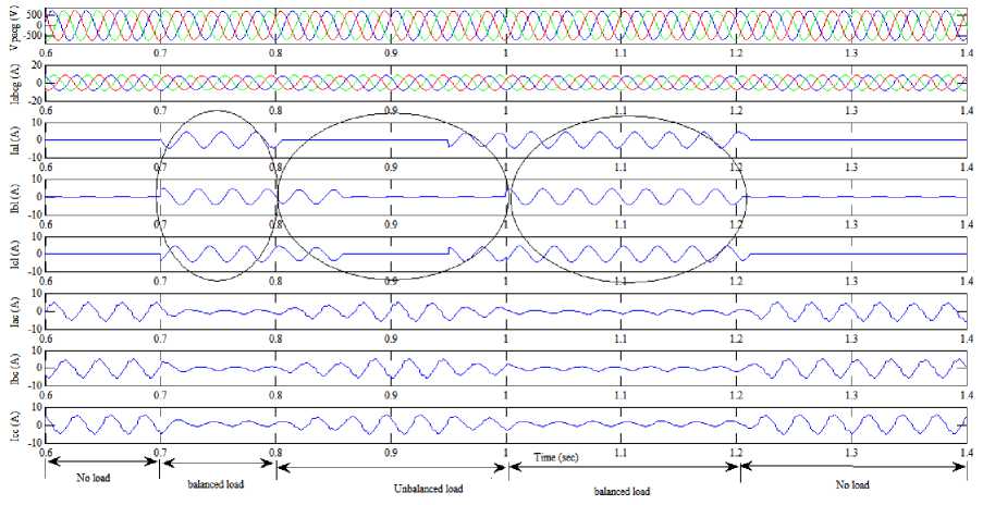
Fig.4. Simulated transient characteristics waveforms of voltage generated by three-phase IIG (V abcg ), three-phase IIG currents (I abcg ), per-phase resistive load currents (I al, I bl, I cl ), per-phase VFCU currents (I ca , I cb , I cc ) under balanced and unbalanced resistive load using FPIL controller.
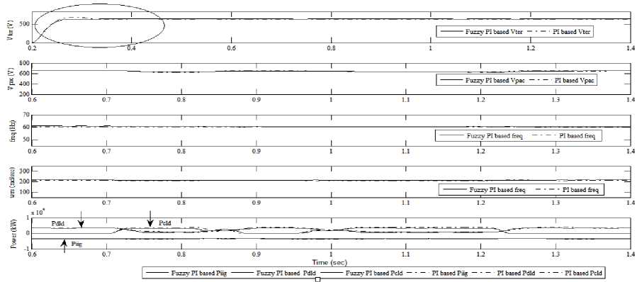
Fig.5. Comparison of the simulated results of magnitude of terminal ac voltage (V ter ) , peak value of generated ac voltage (V pac ), frequency (freq) , rotational speed (wrs), power generated by IIG (Piig), consumer load power (Pcld) and dump load power (Pdld) for pure resistive load using both PI and FPIL controllers.
Fig. 5 also indicates the comparison of simulated results of amplitude of terminal ac voltage V ter , the peak value of generated ac voltage V pac , frequency (freq), speed (wrs), IIG power, consumer load power and dump load power due to both PI and FPIL controllers. It is clearly visualized from the results outcomes; the response of ac voltage V ter is notably faster in FPIL in comparison to traditional PI. Moreover, at the time of load insertion and separation there is smooth and fine control in case FPIL in comparison to traditional PI.
The performance relating to rise time, settling time and overshoot are considerably lower in FPIL than PI controller as mentioned in Table 2. Also, the performance relating to THD values of IIG voltage and current are considerably lower in FPIL than PI controller as mentioned in Table 3.
-
B. Simulation based Performance outcomes of IIG-VFCU system with three-phase balanced and unbalanced reactive load
Fig. 6 indicates the FPIL controller based transient performance characteristics of three-phase IIG supplying 0.8 p.f lagging R-L load. The 3-phase reactive balanced load is incorporated through circuit breakers to the generator terminals at 0.7 sec. This results in rise in load currents and drop in VFCU currents to balance the IIG system. With the separation of one phase at 0.8 sec and another phase of load at 0.85 sec, the load becomes unbalanced and hence VFCU currents of two phases increase for balancing the IIG system. At 0.95 sec one-phase and at 1 sec another phase of load is reinserted at IIG terminals. Under such situation, VFCU currents die down to zero value to make IIG system balanced. It means that the controller current increases and decreases when the consumer load decreases and increases respectively. It shows that both the consumer load current and dump load current are complementary in nature. Because of the complementary nature of load and controller current, the load on the generating unit is held constant. Hence, the voltage, frequency, rotational speed and the generated power of the IIG remains constant even at varying load conditions [Fig. 6 and Fig. 7]. In reactive load situation, generator voltage is constant and is perfectly sinusoidal which shows that VFCU is working as a voltage supporter and load balancer.
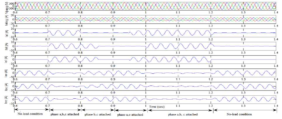
Fig.6. Simulated transient characteristics waveforms of voltage generated by three-phase IIG (V abcg ), three-phase IIG currents (I abcg ), per-phase reactive load currents (Ial, Ibl, Icl), per-phase VFCU currents (Iac, Ibc, Icc) under balanced and unbalanced reactive load using FPIL controller.
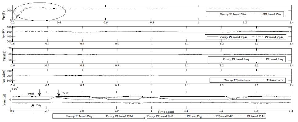
Fig.7. Comparison of simulated results of magnitude of terminal ac voltage (V ter ), peak value of generated ac voltage (V pac ), frequency (freq) , rotational speed (w rs ), power generated by IIG (P iig ), consumer power (P cld ) and dump load power (P dld ) for resistive-inductive load using both PI and FPIL controllers.
Fig. 7 also indicates the comparison of simulated results of amplitude of terminal ac voltage (Vt er ), the peak value of generated ac voltage V pac , frequency (freq), speed (w rs ), IIG power, consumer load power and dump load power due to both PI and FPIL controllers. In Fig. 7(a), the responses of ac voltage V ter attained using FPIL controller is remarkably faster than PI controller. The settling time for V ter due to PI is 0.45 sec whereas due to
FPIL controller is 0.34 sec [Table 2]. From Fig. 7, it is observed that the amplitude of terminal ac voltage, peak value of generated ac voltage, frequency, rotational speed and power generated by the IIG are constant. Also, the performance relating to THD values of IIG voltage and current are considerably lower in FPIL than PI controller as mentioned in Table 3.
-
C. Simulation based performance outcomes of IIG-VFCU system with three-phase balanced/unbalanced non-linear load
Fig. 8 indicates the FPIL controller based transient performance characteristics of three-phase IIG voltage (Vpabcg), three-phase IIG currents (Iabcg), per-phase resistive load currents (I al , I bl , I cl ), per-phase VFCU currents (I ac , I bc , I cc ) furnishing non-linear rectifier load. The non-linear rectifier load is formed by using three-phase diode rectifier with resistive load and capacitive type filter at its DC end side. At 0.7 sec, a balanced nonlinear load is inserted then the VFCU currents are reduced within a cycle for regulating the power, frequency and these becomes non-linear for eliminating harmonic currents. On separation of one phase of the load at 0.85 sec, the load becomes unbalanced but the IIG currents remain balanced, which shows the load balancing aspect of the controller. The speed of the IIG is constant throughout the whole generating processes which show that the IIG is generating constant voltage, frequency and power [Fig. 8 and Fig. 9]. Fig. 9 indicates the comparison of simulated results obtained using PI and
FPIL method for magnitude of terminal ac voltage, peak value of generated voltage (V pac ), frequency (freq), rotational speed (w rs ), power generated by IIG (P iig ), consumer power (Pcld) and load power (Pdld) for nonlinear rectifier load. The results obtained by using both methods are quite satisfactory and comparable in terms of performance .But the response of ac voltage V ter due to FPIL is notably faster and smoother than traditional PI controller [Fig. 9 (a)].
Fig. 10 indicates the THD values of IIG voltage (V pa ), IIG current (I ag ), consumer load current (I al ) under balanced and unbalanced load conditions using Powergui FFT Analysis Tool. It is concluded from the figure, the THD of V pa and I ag is lower than the limit of 5 % mentioned in IEEE-519 standard document.The comparison of THD values of IIG voltage and current under different loads using both methods is depicted in Table 3. It is noticed from table 3, the THD values of Vpa and I ag using FPIL under different loads is significantly less than PI based control criteria. The THD values are also less than the earlier published research.
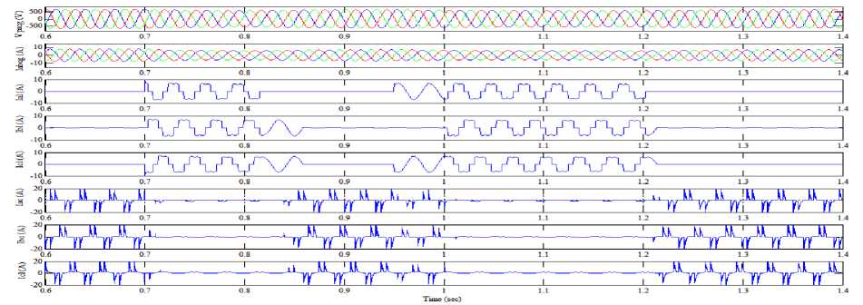
Fig.8. Simulated transient characteristics waveforms of voltage generated by three-phase IIG (Vabcg), three-phase IIG currents (Iabcg), per-phase nonlinear load currents (I al, I bl, I cl ), per-phase VFCU currents (I ac , I bc , I cc ) under balanced and unbalanced nonlinear rectifier load using FPIL controller.
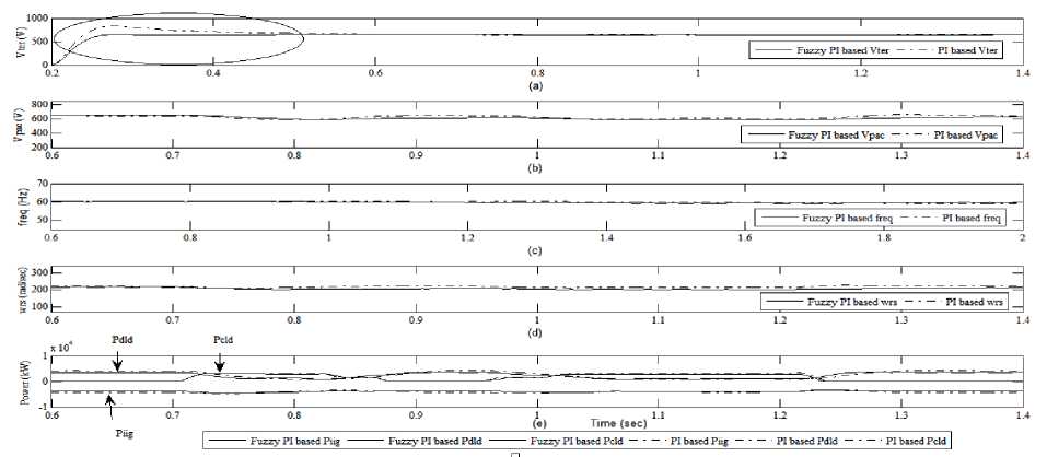
Fig.9. Comparison of magnitude of terminal ac voltage (Vter), peak value of generated ac voltage (Vpac), frequency (freq), rotational speed (wrs), power generated by IIG (P iig ), consumer power (P cld ) and dump load power (P dld ) for non-linear rectifier load using both PI and FPIL controllers.
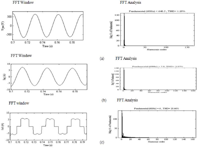
Fig.10. FFT window and FFT analysis of (a) IIG voltage V pa (b) IIG current I ag and (c) Consumer load current I al under both balanced and unbalanced load.
Table 2. Performance of VFCU regarding or relating to rise time, settling time and overshoot
|
Load Type |
Controller type |
Rise time (sec) |
Settling time (sec) |
Overshoot |
|
Resistive |
PI controller |
0.0434 |
0.3681 |
7.7549 |
|
Load |
Fuzzy PI controller |
0.0426 |
0.2687 |
0.6121 |
|
Reactive |
PI controller |
0.0450 |
0.4605 |
9.1064 |
|
Load |
Fuzzy PI controller |
0.0418 |
0.2861 |
0.0170 |
|
Non-linear |
PI controller |
0.0478 |
0.8023 |
28.1646 |
|
Load |
Fuzzy PI controller |
0.0419 + |
0.6142 + |
0.0045 + |
Table 3. Performance relating to THD value of IIG voltage and current
|
Load Type |
Controller type |
THD values in % |
|
|
IIG voltage (V) |
IIG current (A) |
||
|
No Load |
No controller |
8 % |
5.04 % |
|
Resistive Load |
PI controller |
1.42 |
3.57 |
|
Fuzzy PI controller |
1 |
2.71 |
|
|
Reactive Load |
PI controller |
1.54 |
3.93 |
|
Fuzzy PI controller |
1.25 |
2.75 |
|
|
Non-linear Load |
PI controller |
2.26 |
4.09 |
|
Fuzzy PI controller |
1.29 |
2.87 |
|
-
VI. Conclusion
The complete performance of the system under both transient and steady state are adjudged using both traditional PI and Mamdani based FPIL for VFCU. The performance relating to voltage, frequency, speed and power etc are analyzed and compared using both methods. Table 2 shows that FPIL type controller provides better performance pertaining to rise time, settling time and overshoots. Table 3 shows that the THD values of the IIG voltage and current using FPIL based controller are less than traditional PI based controller.
These values also lies within the range mentioned in
IEEE 519 standard document. Thus FPIL based VFCU behaves as a load balancer, voltage and frequency supporter and a THD reducer. Hence, performance enhancement of IIG is achieved using FPIL based VFCU than the PI controller. But in Mamdani based FPIL, this enhancement in performance is achieved at the cost of an increase in computational needs. However, the computational needs are lesser in PI controller. Such types of intelligent systems are cost effective and can also be used for electrification purposes in remote and grid isolated areas or for pico-hydro based applications.
Appendix A
A 3-phase star connected Induction machine of rating 5 HP, 460 V, 60 Hz, pole pairs 2 for the simulation study and testing. The other technical details are:
-
A. Various electrical parameters in per-unit (p.u)
R st = 0.01965
X lst = 0.03969
R ro ’ = 0.019087
X lro = 0.03969
X mag = 1.3534
Inertia factor, JF = 0.09526
Friction factor, FF = 0.05479
Saturation characteristics in p.u
^тад = 1.1799 I mag < 0.212
L = 0.0814 1^ - 0.5533 I + 0.9943
0.212 < I < 4.576
L = 0.1159 4.563 < I < 6.476
^тад =0 ^тад > 6.4763
-
B. Prime mover characteristics in p.u
T shaft = a1 -а2 ∗ԝrs a1=2.36, a2=1.011
-
C. PI based controller gains
Optimal values of gains
K pac = 32.4
Ki ac = 1.24
References Traditional PI and FPIL based VFCU for an isolated induction generator (IIG)
- R.C. Bansal, “Three-phase self-excited Induction Generators: An Overview,” IEEE transactions on Energy Conversion, vol. 20, pp. 292-299, June 2005.
- J.M. Elder, J.T. Boys and J.L., “Woodward, Integral cycle control of stand-alone generators,” IEE Proc., vol. 132, pp. 57-66, March 1985.
- R. Bonert and S. Rajakaruna, “Self-excited Induction Generator with excellent voltage and frequency control,” IEE Proc. Gener Transm. Distrib, vol. 145, pp. 33-39, January 1998.
- Chandra, T.S, Bishnu, P.M., “Voltage regulators for self excited induction generator,” IEEE Transactions on Energy Conversion, vol. 20, pp. 460-463, April 2004.
- S.C Kuo and L Wang, P.M., “Analysis of voltage control for a self-excited induction generator using a current-controlled voltage source inverter (CC-VSI),” Proc. Inst. Elect. Eng., Transm. Distrib, vol. 148, pp. 431-438, September 2001.
- E. Suarez and G. Bortolotto, “Voltage frequency control of a self-excited induction Generator,” IEEE Trans. Energy Convers , vol. 14, pp. 394-40, September 1999.
- B. Singh, S.S. Murthy and S. Gupta, “Analysis and implementation of an electronic load controller for a self-excited induction generator,” IEE Proc. Gener. Transm. Distrib, vol. 151, pp. 51-60, January 2004.
- B. Singh, S.S. Murthy and S. Gupta, Analysis and design of an electronic load controller for a self-excited induction generator,” IEEE Trans. On Energy Conversion, vol. 21, pp. 285-293, March 2006.
- Sarsing Gao, S.S Murthy, G. Bhubaneswar and M. Sree Lalitha Gayathri, “Design of microcontroller based electronic load controller for a self-excited induction generator supplying single-phase loads,” Journal of Power Electronics, vol. 10, pp. 444-449, July 2010.
- Juan M. Ramirez and Emmanuel Torres M., “An Electronic load controller for self-excited induction generators,” IEEE PES General Meeting, June 2007.
- Shakuntla Boora, S.K Agarwal, K.S Sandhu, “Electronics based dump load controller for an grid isolated Asynchronous Generator,” International Journal on emerging Technologies, vol. 6, pp. 9-14, June 2015.
- M.H. Rashid, Power Electronics Circuits, Devices and Applications, 3rd ed. Pearson / Prentice-Hall, Singapore, 2004.
- IEEE Guide for harmonic Control and Reactive Compensation of Static Power Converters, IEEE Standard 519, 1992.
- E.G. Marra and J.A. Promilo, “Induction- Generator- based system providing regulated voltage with frequency constant,” IEEE Trans. Ind. Electron, vol. 47, pp. 908-914, Aug 2000.
- Ramji Tiwari, Ramesh Babu. N, "Comparative Analysis of Pitch Angle Controller Strategies for PMSG Based Wind Energy Conversion System", International Journal of Intelligent Systems and Applications (IJISA), vol. 9, pp. 62-73, May 2017.
- Sachin Sharma, Bhim Singh, “Fuzzy proportional-integral regulators for stand-alone wind energy conversion system”, IEEE Conference ICPCES, pp.1-8, January 2011.
- Sakshi Bangia, P R Sharma, Maneesha Garg, "Simulation of Fuzzy Logic Based Shunt Hybrid Active Filter for Power Quality Improvement", International Journal of Intelligent Systems and Applications (IJISA), vol.5, pp.96-104, January 2013.
