Transient Processes on the Elements of Underground Installations

Author: Bojan L. Jovanović, Slobodan N. Bjelić, Nenad A. Marković
Journal: International Journal of Information Technology and Computer Science(IJITCS) @ijitcs
Article in issue: 9 Vol. 9, 2017.
Free access
If the value of the field is greater than the disruptive voltage of the soil around earth wire (probe) the breakthrough occurs and the majority of soil becomes conductive. Particular problem are components of high frequency currents or voltages. Disorders of frequency in the range of 50 Hz to 5 kHz that can affect the selection of installation parameters, in compliance with all environmental criteria, are simulated by adapted subprogram in the part of the package Sym Power MATLAB.
Installation, Conductor, Grounding, Environment, Protection
Short address: https://sciup.org/15012677
IDR: 15012677
Text of the scientific article Transient Processes on the Elements of Underground Installations
Published Online September 2017 in MECS DOI: 10.5815/ijitcs.2017.09.01
-
I. Introduction
Both spatial position and system ratio are determined by projecting and thus are provided optimal parameters for the system functioning and adaptation to variable parameters in the use of energy (electrical, thermal or some other) [1,2]. The standards that must be followed and which are related to electrical installation are IEC IEC 60364-(4, 5, 6, 7) and IEC 60529, IEC 61032 [3].
There is no universal method for analysis of transient processes arose from the current leakage into the ground because of various disturbances, faults or static discharges. Therefore, new methods for design of architecture of networks and installations and testing of installations have been introduced. There are significant changes in the names/terminology and definitions of hazards and measures of protection and larger number of new data needed for designing and maintenance. Changes in the terminology are not just the product of one standard but an application of logic of correct professional translation from other languages.
Direct or indirect atmospheric discharges damage the plant at the distance of a few kilometers. Commutating surges due to transient process and at f = 50 Hz can lead to the same result and solutions are prescribed by IEC standard.
Grounding is selected in accordance with the local recommendations, limitations in supply and types of load. Amendment and improvements of the regulation within the Republic of Serbia, compared to the previous contributions are: to introduce new adequate terminology and formulate numerous new demands, for example in the domain of eco-projecting, testing and maintenance of electrical installations. Before testing and before putting the installation into operation the norms of periodical testing are adopted.
The basic materials that are used for manufacturing of conductive elements of underground installations and earthing and earthing conductors for protection of people and facilities from dangerous impacts of the current and static discharges are copper and aluminium. When selecting the material, apart from electromagnetic impact, it is necessary to take into account the chemical impact, primarily of corrosion. Technical, economic and environmental criteria require that in the design and selection of geometric dimensions of the grounding elements computers and special software are to be used [4, 5].
Natural elements (metal cable sheath, tubes, ferroconcrete fundaments, etc.) and groundings type A and V are also used for the grounding [6]. Voltage must not exceed value of 10 kV. If voltages on the grounding are higher than 5 kV the protective measures must be foreseen. According to IEC requirements, the protective devices must comply with the grounding in order to quickly disconnect the power supply when voltage reaches the values dangerous to the body. The currents around the grounding that affect the disturbances on the lines (those are often the tubes) [7].
The paper is organized as follows: In Section 2 is given a literature review of relevant papers dealing with underground electrical installations. In Section 3 is presented the calculation of transient processes on conductive metal elements of underground installations where a possible equivalent scheme of a part of the grounding of underground installations is also given. Simulation results, where the model is metal cylindrical tube of the given material, length and diameter are presented in Section 4. Finally, in Section 5 are given some concluding remarks.
-
II. Related Works
Dealing with the problem of transient processes on the elements of underground electrical installation is not a new phenomenon. Many studies have been conducted regarding this topic and many papers have been dealing with this issue.
In the last century Kulda [5] was dealing with the problem of underground electrical installations who suggested that this problem should have computer-based approach because he came to the conclusion that faster and simper solutions were obtained (although we must admit that in that period, computer technology was not nearly as developed as today). In the opinion of L. Van der Sluis et al. and Z. Bogicevic et al. [8,9], the projecting of the systems of underground electrical installations is in fact planning and selecting of parameters of its structure in relation to the given functions and technical management of the system. Velickovic [10] also gave great attention to this problem who for the model chose the metal pipes of the cylindrical shape using the method of finite elements. Also Bjelic et al. [7] in their paper deal with the insulation layers of metal tubes of underground installations (gas, water...) which do not provide their full protection against the corrosion and malfunction. Structure and diversity of shapes of underground installations tubes greatly impede the analytical solution that it becomes almost impossible, even when computer is used. Thus, the authors concluded that the solution of the problem can be obtained only with the use of the model for determination of voltage at the insulating layer of the metal tube of the underground installation.
-
III. The Calculation of Transient Processes on Electric Conductive Metal Elements of Underground Installation
The character of transient process in the soil is determined by the size of the source (voltage/current) [11, 12] and parameters of the soil. The parameters of the soil are: lL , g i c , and the sources (voltage/currents) are: l [ H/m ] = inductivity, r [ q /m ] = active resistance,
g [ S / m ] = conductivity and c [ F / m ] = capacitance. If the conductivity parameter g is not given (current conducted to ground), then it is determined according to the relation: R = 1 /gl [ q ] [13, 14]. For small values of impulsive discharge current conducted to the ground, which can be considered as linear time function i ( x,t ) = a ■ t the radial earth wire behaves as the long line which part A x has the following parameters r , l L , g and c , FIg. 1.
The values of currents/voltages are estimated from the first and the second telegrapher’s equations [15]. The section of the earth wire is replaced with a scheme (Fig. 1) and the process is described by differential equations:
-
-®^ = r ■ i(x,t)+k .(1)
dx xd
-
-*У1 = g■ U(x,t)+ C.(2)
dx '
The second equation in the system of equations (1) and (2) is obtained as follows: Elementary cylindrical segment of conductive grounding structure is bordered by transverse planes x i x + d x normal to universal axis X = x; y (relevant for both axes x and y ) i.e., are bordered by planes x and x + dx , or planes y and y + dy . The output flux of a vector J through the external edge plane of cylindrical conductor element with surface density n of the axis is determinate from the continuity equation [16, 17]:
J jds sp = — d J n ■ d ^ ■ d x . (3) Ssp Con. 1
If a specific electrical conductance of dielectric around the elements of the earth wire has cylindrical shape O del * 0, then the flux of the vector J (left side of equation (3)) has three components: two fluxes of equal value through transversal input x : J -J dS > x = - i and
Sx output cross-sectionx + dx :
J JdS x + d x i + () x d x
S x + d x
and flux through external sheath: f ^ dtel E n d t d x . En
Con. 1
is a normal component of the field strength on the surface of external sheath. The equation (3) then becomes:
— i +1 i +
^T ^V f ^ diel E n d 1 d X = - v f n d 1 d X •
5X 1 cOn.l^cOn!
f £dielEnd1 = fnd1 = q = cv •(6)
Con.1
where c — capacitance of the elements to the ground wire, v — voltage.
By substituting the parameters £ / s ] diei c = g (conductivity of the elements of conductive structure) the second basic analysis equation is obtained:
di — + dX
f ^ diel E nd- 1 = —^ J nd 1 •
Con. 1
Con. 1
' i + £ dX L £
dv c • v = — c — or diel d t
—
According to the theory of fluxes from the [16, 17] the following equation has been known:
d i
= g dX
d v v + c — d t
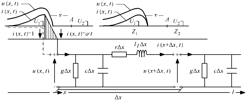
Fig.1. The equivalent scheme of a part of the grounding and the current/voltage waveform.
The system of ordinary differential equations is transferred to more complex domain:
-
— dr" = ( r + Pl L ^ I ( x ^ • (8)
dx
-
— d 1 = ( g + pc U ( x ) • (9)
By increasing the order for one the second order equations are obtained. For voltage and current the d’Alambert’s equations that apply for wave processes [18]:
-
— d U^(x) — (r + p )(g + pc)U(x) = 0 .(10)
dx 2
-
— d I(x) —(r + p )(g + pc)1 (x ) = 0.(11)
dx 2
U(x) = A • eY + B • e-^x .(12)
dU ^ x ) = a • y • e Y — B • у • e "^ x = y ( A • e Y — B • e "^ x ) .
d^Ux) = Y 2 • U(x).(14)
dx 2
The root of the equation is the constant of electromagnetic wave propagation in the ground:
Y = V(r + plL)(g + pc) = P + ja • у 2 =(r + plL)(g + pc ) =
= в 2 — a 2 + 2 j ap = rg + p 2 L + p (h g + rc )
where:
P = 11 (rg + p 2 L)+ 1 V(r2 — p 2lL 2 )(g 2 — p 2c2 ) • a =
— 1 (rC + p2lLc) + 1 V(r2 — P2lL2 )(g2 — P^ .
I ( x ) =— —( A ■ e Y — B ■ e ~Y ) = Z 0
From the equation — ^^ = ( r + —lL ) I ( x ) dx
and
— | e Y +1 | e -^ = Ae Y + Be
Z 0 J I Z 0 J 1 1
I ( x ) =
—
T ( A-eY
Z 0
— B ■ e?x )
follow is:
I ( x ) = IpCh Y x— sh y x .
p Z 0
Z 0 =
(r + Pll )l (g + Pc У
The value Z 0 is called wave impedance and it is:
--~ — ( r + Pl L )( g + Pc ) U ( x ) = 0 dx 2
d 2 U dx 2
— Y 2 ■ U ( x ) = 0
Y 2 = ( r + Pl L )( g + pc ) . (21)
U ( x ) =— g c ■ ( A ■ e Y — B ■ e —Y ) . (22)
V r + PlL
Current and voltage at the initial part of the earth wire (place where current enters the soil) is:
If the phase value of the current that enters the ground at the point ( *x x = 0 ) has the amplitude value i ( x x = 0 ,t ) = a ■ t = 1 0 , the solution of the expression (32) is i ( x,t ) = A i e Y + B i e Y . The value of integrating constants is obtained from the boundary conditions at the entrance of the current into the ground i ( 0 ,t ) = A i e Y 0 + B i e Y 0 = A i + B i = 1 0 and at the end of the earth wire i ( l, t ) = A i e Y + Be Y = 0.
In the system of unit values (per unit) is i ( xx = 0 ,t ) = a ■ t = i, where the solution of the expression (32) is i ( x,t ) = A i e Y + B i e Y (initial conditions). The constants A 1 ,B 1 are obtained from the boundary conditions of the entrance of the current into the ground i ( 0 ,t ) = A i e Y 0 + B i e Y 0 = A i + B i = i and, finally, earth wire i ( l,t ) = A i e Y + B i e — Y l = 0:
U x = U p = U i . (23)
|
I x = o = 1 0 = I i = I p . |
(24) |
|
|
i.e.: |
x = 0. |
(25) |
|
U p = A + B . |
(26) |
|
|
Z 0 I p = — A + B . |
(27) |
|
|
B = i ( u — + Z 0 ■ I — ) . |
(28) |
|
|
A = 2( u — — Z 0 ■ I — ) . |
(29) |
|
|
e " + e Y e Y — e ^ x U ( x ) = Un Z(\I n . p 2 0 p 2 |
(30) |
|
|
U ( x ) = U — ■ ch y x — Z 0 1 — ■ sh y x . |
(31) |
Vrms = i , 73 kV i f = 50 Hz, 0, 5 kHz, i kHz.
IV. Simulation Results
Obtained analytical considerations show the functional possibilities of the model with different frequencies.
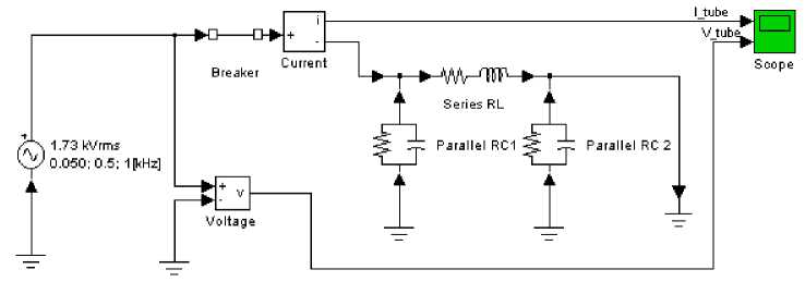
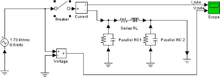
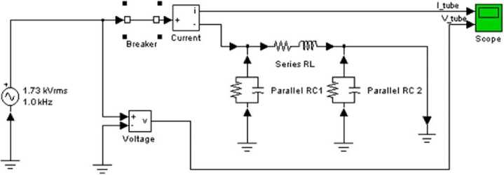
The preparation of computer programs in the method of organized modelling in technical literature is called preprocessing (forming of model of technical system). The simulation program is realized based on the scheme given in Fig. 2 in a new subprogram “Transient analysis of current and voltage beginning a linear circuit metal tube”, since the cylindrical metal tube of given material, length and diagram is used as a model. The scheme and diagram are provided for each test.
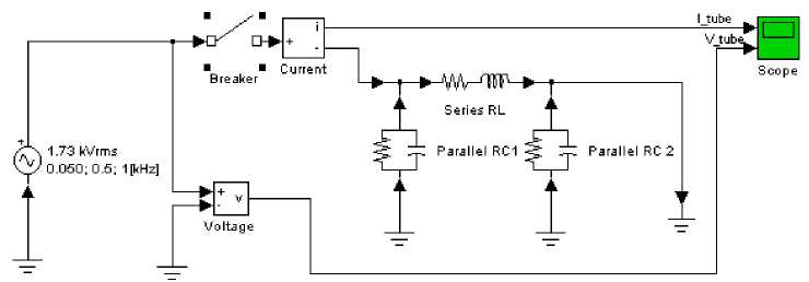
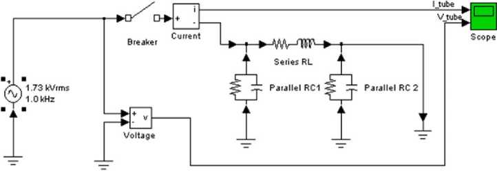
Description of the schemes: The schemes on Fig. 2-7 present the transient processes where the simulation was performed for different values of the frequency, both with open and closed breaker at the beginning of the loop.
Below is given information regarding the source of parameters, resistance, inductanse and capacitance:
In series combination each segment has following parameters:
R = 2 . 56 e-03 [Ohm],
L = 1 . 78 e-06 [H],
In parallel branch each segment has following parameters:
R = 0 . 477 e-03 [Ohm],
L = inf [H],
C = 18 . 53 e-11 [F].
Simulation: After the transient period of about a few ms , the system reaches the steady-state. The waveforms of the currents and voltages components of different frequencies are recorded.
C = inf [F]
a)
Transient analysis of current and voltage beginning point a linear circuit metal tube
b)
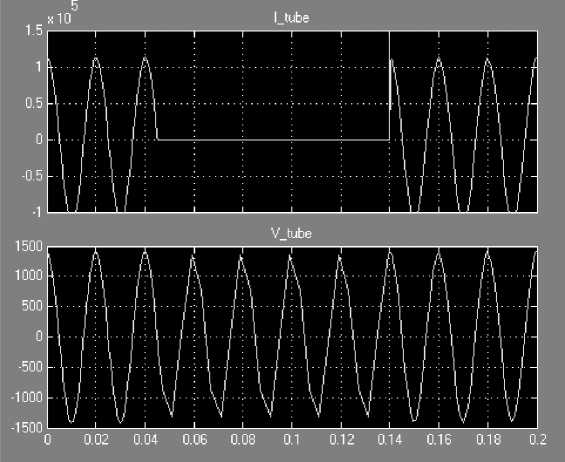
Fig.2. Transient analysis of linear circuits: a) Scheme simulation Close Breaker, b) the waveform of the current and voltage Vrms = 1 , 73 kV and f = 50 Hz.
a)
a)
Transient analysis of current and voltage beginning point a linear circuit metal tube
b)
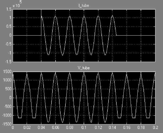
Fig.3. Transient analysis of linear circuits: a) Scheme simulation Open Breaker, b) the waveform of the current and voltage Vrms = 1 , 73 kV and f = 50 Hz.

Powergui - С о nti n u о us
Transient analysis of a linear circuit
Double click on the More Info button (?) for details

More Info
a)
b)
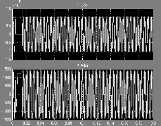
Fig.4. Transient analysis of linear circuits: a) Scheme simulation Close Breaker, b) the waveform of the current and voltage Vrms = 1 , 73 kV and f = 0 , 5 kHz.
Powergui -Continuous
Transient analysis of a linear circuit
Double click on the More Info button (?) for details
b)
More Info
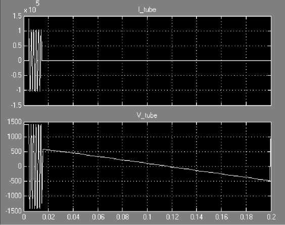
Fig.5. Transient analysis of linear circuits: a) Scheme simulation Open Breaker, b) the waveform of the current and voltage Vrms = 1 , 73 kV and f = 0 , 5 kHz.
a)
a)
Powergui -Continuous
Powergui •Continuous
b)
Transient analysis of a linear circuit

More Info
Double click on the More Info button (?) for details
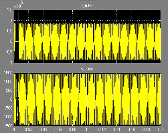
Fig.6. Transient analysis of linear circuits: a) Scheme simulation Close Breaker, b) the waveform of the current and voltage Vrms = 1 , 73 kV and f = 1 kHz.
Transient analysis of a linear circuit
Double click on the More Info button (?) for details

More Info
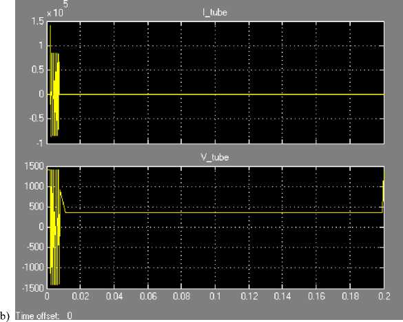
Fig.7. Transient analysis of linear circuits: a) Scheme simulation Open Breaker, b) the waveform of the current and voltage Vrms = 1 , 73 kV and f = 1 kHz.
For the same values of parameters of pipes’ segments: resistance R , inductance L and capacitance C , the values of shock waves witd frequency 50 Hz, 0,5 kHz and 1 kHz have been tested. The results that correspond to currents and voltages are represented in diagrams recorded in Scope. When the switch breaker is open, the voltage waves last shorter, which the result expected of authors of simulation; when the switch (breaker) is open, the duration of current and voltage waws is nuch longer. The intensities of voltage waves correspond to given values on electric source. This confirms the possibility of simulation of transient electromagnetic processes on electro-conductive metal tubes of underground installation.
Based on the previous diagrams we can conclude that the advantages of MATLAB are the large number of possible simulations, and results of those simulations, shapes and characteristic values of obtained wave diagrams verify the proposed model for consideration of transient processes on elements of underground installations.
Finished MATLAB Sumulink program quite accurately simulate the asymmetrical loads, but own development of both models and programs has special advantages, such as detailed insight into all components of the model and program, and introduction of various changes that otherwise could not be made in the available program packages.
-
V. Conclusion
Determination of the voltage dependence along radial electric conductive elements of different lengths is conducted according to presented method. As the shapes of the time flows of currents and voltages show, the developed analytical procedure and formulas obtained can be used for estimation of the impact of the parameters of unit resistances, inductance, conductivity and capacitance on the values of currents and voltages that passes through the conductive elements of underground installations. The impact of the wide range of the frequencies was also tested, by which was simulated the occurrence of higher harmonics and their impact on metal parts of the installation in the ground. The results show that the values of currents along the grounded conductive metal parts of the installation have the constant values, and voltages at small conductor lengths of several meters decline rapidly.
References Transient Processes on the Elements of Underground Installations
- Lou van der Sluis, Transients in Power Systems, John Wiley & Sons Ltd, 2001.
- A.A. Mahfouz, M.K. Mohammed, F.A. Salem, “Modeling, Simulation and Dynamics Analysis Issues of Electric Motor, for Mechatronics Applications, Using Different Approaches and Verification by MATLAB/Simulink”, International Journal of Intelligent Systems and Applications, IJISA2013, Vol. 5, No. 5, pp. 39-57, April 2013, DOI: 10.5815/ijisa.2013.05.06.
- Standards: IEC 60364-(4, 5, 6, 7) i IEC 60529, IEC 61032.
- M. Mišić, Z. Bogićević, S. Bjelić, “Electrodynamic Forces between Electrical Conductors and Cylindrical Magnetic Shields”, British Journal of Applied Science & Technology, 2015, Review Article, Vol. 11, Issue 4, DOI: 10.9734/BJAST/2015/20541.
- J. Kulda, “Magneticke pole v silnoproude electrotechnice”, Academia Praha Ceskoslovenska Akademie Ved., 1974.
- J. Nahman, “Grounding of the neutral point of distribution electrical networks,” Belgrade, 2004.
- S. Bjelić, N. Marković, J. Živanić, “Modelling of em current fields in the networks of underground installations with metal pipes,” Innovations and development, Institute for mining and metallurgy, pp. 49-62 UDK 621.31(045)=861, No. 1, Bor, 2013.
- Z. Bogićević, S. Bjelić, B. Jovanović, M. Mišić, “Neutral grounding points within the general distribution system as an element of environmental protection”, pp. 779-787, 3rd International Academic Conference, Places and Technologies, Belgrade, Serbia, 14.-15.04.2016.
- L. Van der Sluis, W.R. Rutgers, C.G.A. Koreman, “A physical arc model for the simulation of current zero behaviour of high-voltage circuit breakers”, IEEE Transactions on Power Delivery, pp. 1016-1022, Vol. 7, Issue 2, Apr. 1992, DOI: 10.1109/61.127112.
- D. Veličković, “Methods for solving of electrostatic fields,” STIL Niš, pp. 61-89, 1982.
- V. Srb, “Electric installations and low-voltage grids,” Tehnical Paper, Zagreb, 1991.
- J. Surutka, “Electromagnetics”, Construction Paper, Belgrade University, 1966, pp. 231-232, 378-386.
- J.R. Linders, “Electric wave distorsion. Their hidden costs and containment”, IEEE Transactions on Industry Applications, pp. 458-474, Vol. IA-15, Issue 5, Sept. 1979, DOI: 10.1109/TIA.1979.4503690.
- S. Bjelić, Z. Bogićević, “Computer Simulation of Theoretical Model of Electromagnetic Transient Processes in Power Transformers”, Information Technology and Computer Science, IJITCS2013, Vol. 6, No. 1, 1-12 Published Online December 2013 in MECS, DOI: 10.5815/ijitcs.2014.01.01.
- E.G. Andreeva, D.V. Šamec, “МКЕ анализ стационарных магнитных полей с помощью программного пакета АНСYС”: Učeb. Posobie. Omsk”, Izdvo OmGTU, 2002, pp. 92.
- N. Marković, S. Bjelić, U. Jakšić, Z. Bogićević, “Graphical zero-sequence cut-offs method of determining of fault to earth in electrical lines,” pp. 73-76, IEEE Catalog Number: CFP08481-PRT, 9th Symposium on Neural Network Applications in Electrical Engineering, IEEE Conference Publications, Faculty of Electrical Engineering, University of Belgrade, Serbia, September 25-27, 2008, DOI: 10.1109/NEUREL.2008.4685567.
- Z. Bogićević, S. Bjelić, P. Spalević, M. Mišić, “Graph-Analytical Method of Determining Impedance in Electrical Transformers, Mathematical Problems in Engineering,” September 2015, Research Article ID 745629, http://dx.doi.org/10.1155/2015/745629.
- S. Bjelić, N. Jović, “Estimation of deep changes of the specific resistance of the ground by geoelectric probing in the industrial complex “Trepca” in Zvecan,” Tehnika Belgrade, 63; 15a; ISSN: 0040-2176, 2008.
- MATLAB SIMULINK Sim Power System, Copyright 1984-2002 The Math Works, Version 6.5.0,180913a, June 2, 2000.
