Translucent elements as structural part of facade systems

Author: Shmelev G.N., Antonov A.S., Lavrov D.I.
Journal: Строительство уникальных зданий и сооружений @unistroy
Article in issue: 1 (106), 2023.
Free access
The objects of research are translucent elements in curtain wall systems, which are common modern architectural and structural solutions. Method. To determine the stress-strain state of a translucent element as part of curtain wall systems, different calculation methods are applied to calculate insulating glass units under full wind load. These methods are based on recommendations from regulatory documents, Navier Solution and numerical experiments in Mepla ISO program and ANSYS software package. In calculations, insulating glass units have different values of linear dimensions, glass thickness and air gaps. The deformation characteristics of a two-component sealant are determined by testing the material in an experimental setup. Results. Based on the results of the work, the convergence of the methods with each other is considered, and the glass unit with the smallest deformation values in the outer glass from the action of wind loads is determined.
Hinged facade systems, translucent elements, design model, experiment, stress, deformation
Short address: https://sciup.org/143180496
IDR: 143180496 | UDC: 69 | DOI: 10.4123/CUBS.106.7
Text of the scientific article Translucent elements as structural part of facade systems
There is a rising trend in modern construction to expand the use of translucent elements in facade systems in various ways [1]–[3], which makes it relevant to study the features of the stressstrain state of translucent elements [4]–[6]. The study of the features of their stress-strain state helps to develop the most accurate calculation methods based on the actual stress-strain state and the actual materials used in facade systems [7]–[10].
To date, the following types of calculations are mainly used to calculate the stress-strain state of translucent elements [11]–[13]:
-
1) Calculation of translucent elements as part of facade systems according to Russian regulatory document SN 481-75 "Guidelines for the Design, Installation, and Operation of Factory-Glazed Window Units" [14] ( https://docs.cntd.ru/document/1200003309 );
-
2) The calculation of the glass elements in the facade systems based on a linear method known as "Navier Solution";
-
3) Calculation of translucent elements in facade systems in the Mepla ISO program;
-
4) Calculation of translucent elements in facade systems in the Ansys Workbench software package [15],[16].
It is important to notice that facade structures are represented by double-glazed windows [17],[18], and translucent elements are represented by silicate glasses [19]–[22].
For the most accurate and complete considerations of the stress-strain state of translucent elements [23]–[26], various types of double-glazed windows are selected, consisting of identical materials [27] and different linear sizes [28]–[30]:
-
a) Double-chamber double-glazed windows with dimensions of 1x1.5 m, glass thickness of 6 mm, thickness of air layers of 15 mm;
-
b) Double-chamber double-glazed windows with dimensions of 1x1.5 m, glass thickness of 8 mm, thickness of air layers of 15 mm;
Shmelev, G.; Antonov, A.; Lavrov, D.
Translucent elements as structural part of facade systems;
-
c) Double-chamber double-glazed soundproof windows with dimensions of 1x1.5 m, glass thickness of 6 mm, thickness of air layers of 9 and 15 mm;
-
d) Double-chamber double-glazed windows with dimensions of 2.4x3.6 m, glass thickness of 10 mm, thickness of air layers of 18 mm;
-
e) Double-chamber double-glazed windows with dimensions of 2.4x3.6 m, glass thickness of 12 mm, thickness of air layers of 18 mm;
-
f) Double-chamber double-glazed soundproof windows with dimensions of 2.4x3.6 m, glass thickness of 12 mm, thickness of air layers of 9 and 18 mm.
From the literature review, it can be concluded that in order to achieve relevant results, it is important to calculate translucent elements in curtain wall systems using different calculation methods. The main scientific purpose of this work is to calculate the aforementioned types of double-glazed windows and determine the glass unit with the smallest deformation values as well as consider the convergence of the calculation methods with each other.
2 Materials and Methods
The first method of calculation is based on SN 481-75 "Instruction for design, installation and operation of double-glazed windows".
The design load is determined using the following formula:
q p = g + ( q + p ) n + q t + Q at , (1)
where:
-
g – design load from the glass's own weight (for bay windows);
-
q – design wind load;
-
p – design snow load (for bay windows);
-
qt - design load from changes in air temperature determined according to the instructions;
-
qаt - design load from changes in atmospheric pressure determined according to the instructions;
n – coefficient, which is 0.55 for two-layer glazing, and is 0.36 for three-layer insulating glass with equal thickness.
When calculating double-glazed windows with an area of more than 5 m2, qt and qаt loads may not be taken into account.
a) Design load qt , kgf/m2, from air temperature changes is determined by the following formula:
Q t =
Q 1 X hag
where:
-
q t 1 – load determined by the nomogram depending on the accepted values of the glass thickness d, the ratio of the larger side of the double-glazed window to the smaller: b/a = λ, areas of doubleglazed windows F and the average temperature of the air layer t al ;
X hag — sum of the thickness of the air layers in the double glazing, mm.
The average temperature of the air layer in contact with the outer glass is determined by the formula:
t ag = yt n + ( 1 — y ) t out , (3)
where:
-
t in – design indoor air temperature, accepted according to the standards of design of buildings for the corresponding purpose.
t out - design winter outdoor temperature, accepted in accordance with the regulatory documents (SP) for construction climatology and geophysics;
y – coefficient assumed to be 0.39 for two-layer and 0.26 for three-layer double-glazed windows.
b) Design load qаt , kgf/cm2, from changes in atmospheric pressure is determined by the formula:
q ^t I hag q " 15 ,
where:
q att - load, determined according to the nomogram.
c) Calculation of the bending strength of the outer glass of the double-glazed unit is done using the formula:
5 >2
2.3* A *( f )2 + 5.12* f * Л 2 + 0.22) < R ,
5 5 V ) u
where:
f – deflection in the center of the glass from the design load q p , cm;
Ru – design bending resistance, kgf/cm2, assumed to be 150 for display windows and 250 for tempered glass.
The ratio f is determined according to the graph below, depending on the value k calculated by 5 the formula:
k =---- q^--- ( Ь )4 ,
(1 + Л 2)2* E d
where:
E – modulus of glass elasticity.
The second method of calculation is based on a linear method known as "Navier Solution".
The glass is located in the X, Y, Z coordinate system. The glass is located along the X, Y axes, and the movement (bending) occurs along the Z axis. It is also assumed that the glass is hinged due to the rubber gasket. In the diagram (fig. 1), the full linear dimensions of the glass sheet are indicated by the dash-dotted line; the calculated values of the linear dimensions are indicated by the solid line.
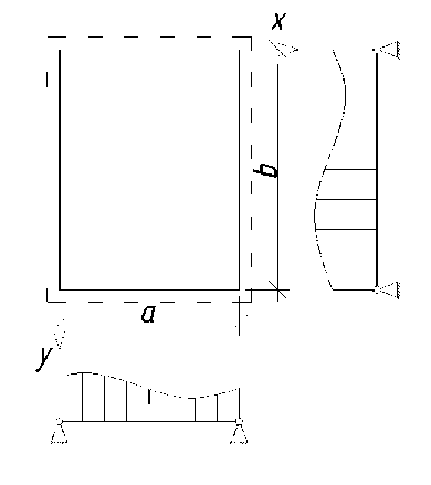
Fig. 1 - Design diagram of glass supported on 4 sides
General calculation of double-glazed windows for deflection is done using the following formulas:
4 αq a w max = з ,
Eh
а
192/ ” ”
= 192 (1 - v 2) s s
П m = 1,3 n = 1,3
m π n π sin sin
2 . 2 a mn m + n b 2
where:
-
w max – maximum deflection in the center of the plate (m);
-
а - coefficient that depends on the aspect ratio of the plate (a / b);
-
π – mathematical constant;
-
v – Poisson ratio;
-
q – uniformly distributed load (P a );
a – smallest side of the plate (m);
b – largest side of the plate (m);
E – Young's modulus of elasticity;
h – plate thickness (m).
For a / b = 1;
а = 0.04609
The next step is a calculation of the glass for the permissible bending stress:
Maximum bending moments in the center of the glass are calculated using the following formulas:
16(7(72 ” ”
16qa x max 4
П m = 1.3 n = 1.3
22a m + vn b2
2 , 2 a mn m + n b 2
m π n π
Sin— Sin— , 22
16 qa 2
M = —-— y max 4
n
^ ^
s s — m=1.3 n=1.3
mn
2 22a vm + n b2
2 . 2 a m + n —^r b 2
m π n π
Sin Sin .
Bending stresses are calculated using the following formulas:
x max
6Mx max h2 ,
y max
6 M y max h
R u ( x , y ) R u x max
y max .
The third method of calculation is based on a Mepla ISO program.
Mepla ISO is a program designed for linear calculation of translucent elements in facade systems, which allows calculating stresses and deformations in double-glazed windows, taking into account the effect of external and internal static loads, the surrounding climatic conditions and the pressure of gases located in the chambers of double-glazed windows. The calculation is based on the Fourier series deviation function on a linear geometric basis. The calculation also uses the Boyle-Marriott law for gases.
The fourth method of calculation is based on Ansys Workbench software package (SP).
There are many software systems (SCAD, Microfe, LIRA-CAD, ANSYS, etc.) used by researchers to model the operation of structural elements. When choosing a software package, the question arises as to how close it is to the actual operation of structures and how accurately it can assess the behavior of a structural element from its zero loading up to its destruction and take into account the stress-strain state under various loads. The Ansys Workbench software package allows accurately and reliably describing the behavior of translucent elements under load.
The computational complex uses finite elements, and the design under study is replaced by a set of discrete elements connected to each other in nodes. When creating a mathematical model, the object under study turns into an idealized calculation scheme representing a system of linear algebraic equations. Moving from the actual structural element to the design scheme, boundary conditions are formulated, and the nodes of the grid of elements are arranged based on the requirements of the problem conditions. The elements are modeled taking into account the strength properties of silicate glass, two-component sealant, and aluminum frame, with the geometric parameters of all the details of the double-glazed window set (Fig. 2, 3).
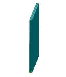
Fig. 2 - Modeling a double-glazed window: general view of the experimental glass unit
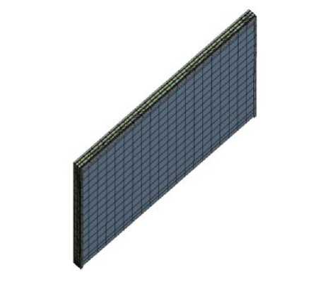
Fig. 3 - Modeling a double-glazed window: computational model by SP ANSYS
In order to obtain the most accurate and complete stress-strain diagram, it is necessary to set the deformation characteristics of a two-component sealant. It is also important to note that in the design scheme, the primary (butyl tape) and secondary (two-component sealant) sealings are combined into one model in order to simplify the calculation. The deformation characteristics of a two-component sealant can be obtained by conducting experimental studies of a standard sample in a test facility. Due to the fact that errors and inaccuracies appear in the production of test samples due to the complexity of manufacturing, standard samples cannot be used. It is decided to use samples made in production Shmelev, G.; Antonov, A.; Lavrov, D.
Translucent elements as structural part of facade systems;
conditions that have linear deviations from standard samples. To ensure that the tests are correct, the height of the new sample is calculated from the condition that the flexibilities of the standard sample and the test sample are equal. To do this, a condition is set:
h . к .
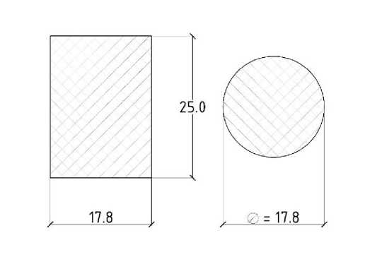
Fig. 4 - Section of a standard sample
The obtained design height values can be used in experimental studies. To do this, the resulting samples are placed in the test unit, and their sequential compression is performed at a speed of 10 mm/min until the deformation is equal to 25%. The compression and load removal cycle are performed 4 times in total. Then the force-strain curve is registered. Thus it is possible to obtain an approximated diagram of a two component sealant.
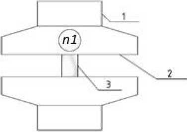
Fig. 5 - Installation for sample testing.
1- fixed part of the installation, 2 - movable part of the installation, 3 - test sample, n1 – indicator
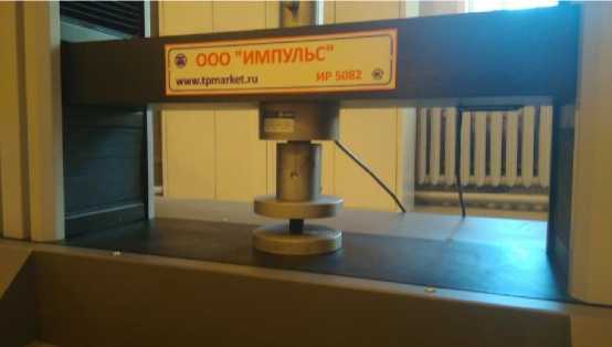
Fig. 6 - Test sample in the «Impulse» press
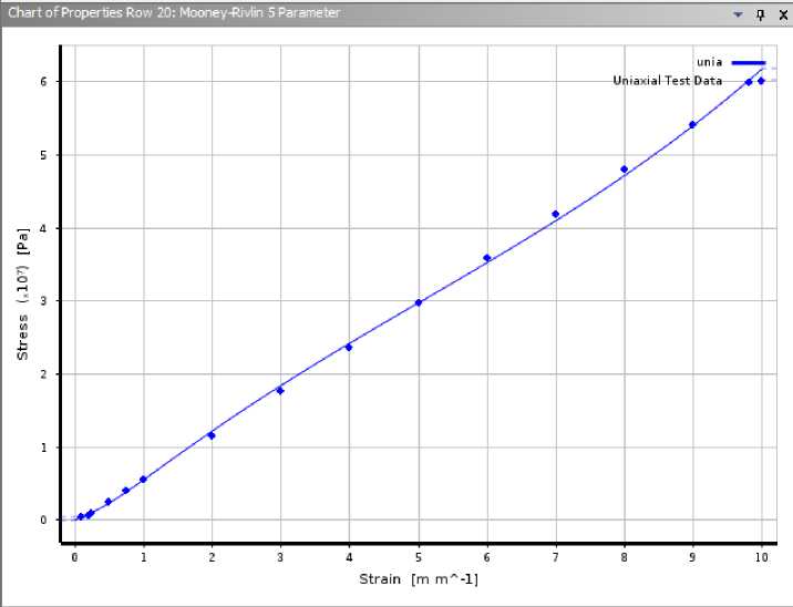
Fig. 7 - Approximated graph of elastic element deformations. Horizontal - strains in %, vertical - stress in pascals (Pa)
3 Results and Discussion
During a calculation based on ANSYS, the physical nonlinearity of silicate glass, aluminum, and two-component sealant is modeled using finite elements operating in a library of material deformation laws. As a result, the nonlinear calculation makes it possible to estimate the development of elastic and plastic deformations in silicate glass, two-component sealant and remote frame and to obtain a destructive load at which the design scheme becomes geometrically variable.
The load applied to the double-glazed window is represented as the total wind load calculated according to Russian regulatory document SP 20.13330.2016 "Loads and actions" [31] , as well as the own weight of the elements included in the design scheme. It is also worth noting that the load from the wind impact is evenly distributed, which allows to model only half or a quarter of the full design scheme; in this case, the operation is performed on a symmetrical reflection relative to the internal faces of the design scheme.
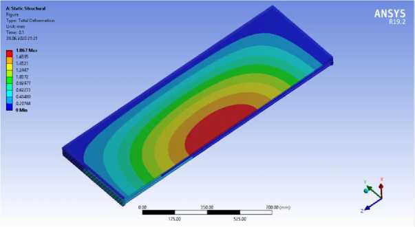
Fig. 8 - Stress-strain scheme of the design model. Mosaic of displacements
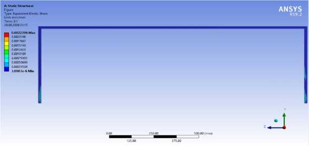
Fig. 9 - Stress-strain scheme of a two-component sealant. Mosaic of stresses
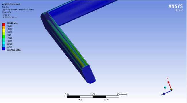
Fig. 10 - Stress-strain aluminum frame layout. Mosaic of stresses
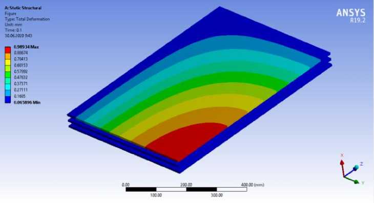
Fig. 11 - Calculation of a double-glazed window unit with dimensions of 1x1.5 m, glass thickness 8 mm, thickness of air layers 15 mm. Stress-strain scheme of a translucent element. Mosaic of displacements
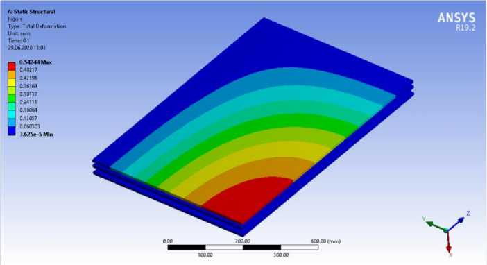
Fig. 12 - Calculation of a double-glazed window unit with dimensions of 1x1.5 m, glass thickness 8 mm, thickness of air layers 9 and 15 mm. Stress-strain scheme of a translucent element. Mosaic of displacements
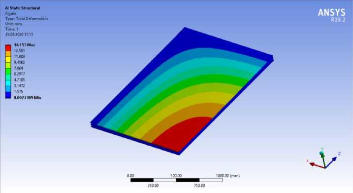
Fig. 13 - Calculation of a double-glazed window unit with dimensions of 2.4x3.6 m, glass thickness 10 mm, thickness of air layers 18 mm. Stress-strain scheme of a translucent element. Mosaic of displacements
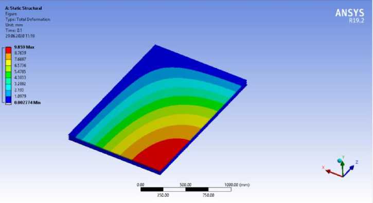
Fig. 14 - Calculation of a double-glazed window unit with dimensions of 2.4x3.6 m, glass thickness 12 mm, thickness of air layers 18 mm. Stress-strain scheme of a translucent element. Mosaic of displacements
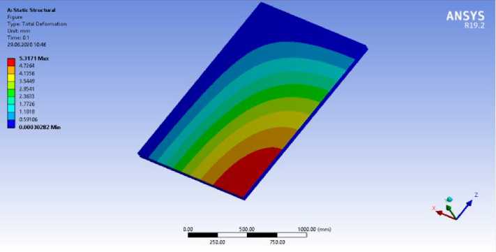
Fig. 15 - Calculation of a double-glazed window unit with dimensions of 2.4x3.6 m, glass thickness 12 mm, thickness of air layers 9 and 18 mm. Stress-strain scheme of a translucent element. Mosaic of displacements
Research in the SP Ansys Workbench gives the results in the form of deformation development patterns when applying wind load and self-weight load. Deformation patterns clearly show the sequence of deformations in a translucent element, as deformations develop sequentially from a more stressed zone to a less stressed one; from the middle to the edges of the translucent element. It is also worth noting that the obtained patterns of deformation development correspond to the development of deformation described in the previous methods for calculating translucent elements.
Deformation values obtained for each type of calculation of translucent elements are listed in the following summary table:
Table 1. Deformation summary table
|
Glass 1x1.5 |
a, m |
b, m |
δ, mm |
SN 481-75 "Instruction for design, installation and operation of double-glazed windows", w max (mm) |
Navier Solution, w max (mm) |
Mepla ISO, w max (mm) |
Ansys Workbench, w max (mm) |
|
15 + 15 |
1 |
1.5 |
6 |
4.5 |
2.875 |
3.01 |
1.867 |
|
15 + 15 |
1 |
1.5 |
8 |
2 |
1.213 |
1.98 |
0,989 |
|
9 + 15 |
1 |
1.5 |
8 |
1.84 |
1.213 |
1.45 |
0.542 |
|
Glass |
|
2.4 x 3.6 |
||||||||
|
18 + 18 |
2.4 |
3.6 |
10 |
7.2 |
3.577 |
14.14 |
14.153 |
|
|
18 + 18 |
2.4 |
3.6 |
12 |
4.8 |
2.07 |
8.82 |
9.859 |
|
|
9 + 18 |
2.4 |
3.6 |
12 |
4.8 |
2.07 |
8 |
5.317 |
|
|
4 |
Conclusions |
|||||||
-
1. Based on the results of the work, the convergence of the methods with each other is considered. Through the process of calculating by the software package, it is possible to get a fairly reliable picture of the distribution of stresses and strains. The convergence of the calculation methods is present, but it is worth noting that the difference with the standard values is quite significant.
-
2. The glass unit with the smallest deformation values in the outer glass from the action of wind loads is determined. The smallest values of the deformation of the translucent element are obtained when calculating the noise insulating glass unit with different values of the thickness of the air chambers.
-
3. The convergence of the methods also shows that during calculation with software package beyond the elastic limit, it is important to analyze the library of laws of deformation of materials and use the corrected diagrams of the library's materials, approaching the analytical diagrams of the work of materials.
References Translucent elements as structural part of facade systems
- Wu, X., Yang, L. and Huang, C. (2015) Nonlinear Bending of Hollow Glass of Curtain Wall under Uniform Loads. Zhongnan Daxue Xuebao (Ziran Kexue Ban)/Journal of Central South University (Science and Technology), 46. https://doi.org/10.11817/j.issn.1672-7207.2015.01.041.
- Lai, C.M. and Hokoi, S. (2015) Solar Façades: A Review. Building and Environment, 91. https://doi.org/10.1016/j.buildenv.2015.01.007.
- Le Bourhis, E. (2007) Glass: Mechanics and Technology. Glass: Mechanics and Technology. https://doi.org/10.1002/9783527617029.
- Kothiyal, G.P., Ananthanarayanan, A. and Dey, G.K. (2012) Glass and Glass-Ceramics. Functional Materials. https://doi.org/10.1016/B978-0-12-385142-0.00009-X.
- Kurenkova, A.Y., Kuzmenko, A.V. and Kurenkova, O.M. (2011) The Formula of Double-Glazed Window in High-Rise Buildings. Magazine of civil engineering, 26. https://doi.org/10.5862/mce.26.10.
- Naumenko, K. and Altenbach, H. (2019) Plates and Shells. Advanced Structured Materials. https://doi.org/10.1007/978-3-030-20381-8_5.
- Ventsel, E., Krauthammer, T. and Carrera, E. (2002) Thin Plates and Shells: Theory, Analysis, and Applications. Applied Mechanics Reviews, 55. https://doi.org/10.1115/1.1483356.
- Greaves, G.N., Greer, A.L., Lakes, R.S. and Rouxel, T. (2011) Poisson’s Ratio and Modern Materials. Nature Materials. https://doi.org/10.1038/nmat3134.
- Huang, C. and Chen, L. (2016) Negative Poisson’s Ratio in Modern Functional Materials. Advanced Materials. https://doi.org/10.1002/adma.201601363.
- Bansal, N.P. and Doremus, R.H. (2013) Handbook of Glass Properties. Handbook of Glass Properties. https://doi.org/10.1016/C2009-0-21785-5.
- Luccioni, B.M., Ambrosini, R.D. and Danesi, R.F. (2004) Analysis of Building Collapse under Blast Loads. Engineering Structures, 26. https://doi.org/10.1016/j.engstruct.2003.08.011.
- Tanojo, E., Pudjisuryadi, P., Candra, B.P. and William, W. (2015) Design Capacity Tables for Structural Steel Based on SNI 03-1729-2002: Built-up Sections. Procedia Engineering. https://doi.org/10.1016/j.proeng.2015.11.141.
- Rao, S.S. (2017) The Finite Element Method in Engineering. The Finite Element Method in Engineering. https://doi.org/10.1115/1.3167179.
- SN 481-75 Guidelines for the Design, Installation, and Operation of Factory-Glazed Window Units. https://docs.cntd.ru/document/1200003309.
- Chen, X. and Liu, Y. (2014) Finite Element Modeling and Simulation with ANSYS Workbench. Finite Element Modeling and Simulation with ANSYS Workbench. https://doi.org/10.1201/b17284.
- Okuzono, T., Otsuru, T., Tomiku, R. and Okamoto, N. (2014) A Finite-Element Method Using Dispersion Reduced Spline Elements for Room Acoustics Simulation. Applied Acoustics, 79. https://doi.org/10.1016/j.apacoust.2013.12.010.
- Alloys, W.A. (2018) International Alloy Designations and Chemical Composition Limits for Wrought Aluminum and Wrought Aluminum Alloys. The Aluminum Association, Arlington, Virginia, ISSN: 2377.
- Spontak, R.J. and Patel, N.P. (2000) Thermoplastic Elastomers: Fundamentals and Applications. Current Opinion in Colloid and Interface Science. https://doi.org/10.1016/s1359-0294(00)00070-4.
- Yuan, Y., Zhou, Y., Wang, L., Wu, Z., Liu, W. and Chen, J. (2021) Coupled Deformation Behavior Analysis for the Glass Panel in Unitized Hidden-Frame Supported Glass Curtain Wall System. Engineering Structures, 244. https://doi.org/10.1016/j.engstruct.2021.112782.
- Ber, B., Premrov, M. and Štrukelj, A. (2016) Finite Element Analysis of Timber-Glass Walls. Glass Structures and Engineering, 1. https://doi.org/10.1007/s40940-016-0015-4.
- Lin, J., Hong, X. and Ren, Z. (2021) Laser In-Depth Heating Thermal Wave Detection of Adhesive Debonding in Glass Curtain Walls: Numerical Simulation and Experiment. Measurement: Journal of the International Measurement Confederation, 177. https://doi.org/10.1016/j.measurement.2021.109268.
- Feng, C., Ma, F., Wang, R., Zhang, L. and Wu, G. (2022) The Operation Characteristics Analysis of a Novel Glass Curtain Wall System by Using Simulation and Test. Journal of Building Engineering, 51. https://doi.org/10.1016/j.jobe.2022.104311.
- Wu, Y. and Flemmer, C. (2020) Glass Curtain Wall Technology and Sustainability in Commercial Buildings in Auckland, New Zealand. International Journal of Built Environment and Sustainability, 7. https://doi.org/10.11113/ijbes.v7.n2.495.
- Piculin, S., Nicklisch, F. and Brank, B. (2016) Numerical and Experimental Tests on Adhesive Bond Behaviour in Timber-Glass Walls. International Journal of Adhesion and Adhesives, 70. https://doi.org/10.1016/j.ijadhadh.2016.06.012.
- Bedon, C. and Amadio, C. (2016) A Unified Approach for the Shear Buckling Design of Structural Glass Walls with Non-Ideal Restraints. American Journal of Engineering and Applied Sciences, 9. https://doi.org/10.3844/ajeassp.2016.64.78.
- Ber, B., Premrov, M., Štrukelj, A. and Kuhta, M. (2014) Experimental Investigations of Timber-Glass Composite Wall Panels. Construction and Building Materials, 66. https://doi.org/10.1016/j.conbuildmat.2014.05.044.
- Sim, J., Yu, S.-H., Yoon, H.-S., Kwon, D.-J., Lee, D.-H. and Bae, J.-S. (2021) Characteristic Evaluation and Finite Element Analysis of Glass Fiber/Recycled Polyester Thermoplastic Composites by Cross-Sectional Shape of Glass Fiber. Composites Part B: Engineering, 223. https://doi.org/10.1016/j.compositesb.2021.109095.
- Ahmad, H., Elnemr, A., Ali, N., Hussain, Q., Chaiyasarn, K. and Joyklad, P. (2021) Finite Element Analysis of Glass Fiber-Reinforced Polymer-(Gfrp) Reinforced Continuous Concrete Beams. Polymers, 13. https://doi.org/10.3390/polym13244468.
- Teotia, M. and Soni, R.K. (2018) Applications of Finite Element Modelling in Failure Analysis of Laminated Glass Composites: A Review. Engineering Failure Analysis. https://doi.org/10.1016/j.engfailanal.2018.08.016.
- Timmel, M., Kolling, S., Osterrieder, P. and Du Bois, P.A. (2007) A Finite Element Model for Impact Simulation with Laminated Glass. International Journal of Impact Engineering, 34. https://doi.org/10.1016/j.ijimpeng.2006.07.008.
- SP 20.13330.2016 Loads and Actions. https://docs.cntd.ru/document/456044318.
