Vane Design Which Based on Finite Element Analyzing Method

Author: Jiabin Tong, Yiming He
Journal: International Journal of Education and Management Engineering(IJEME) @ijeme
Article in issue: 10 vol.2, 2012.
Free access
We have studied the design method of wind power generator vanes. And on the basis of the whole structure’s analysis, we have simplified its structure by studying aerodynamics. We can consider the simplified continuous structure into the combined body which constructed by many finite units which are only connected by means of finite nodes. We have built rigidity equation for every unit firstly on the basis of unit analysis. Then we have gotten the whole structure’s equilibrium equation by combing all units. We have solved the equation by introducing boundary conditions. So we have gotten the approximate solution. During the process of solving, we have mainly studied the analyzing finite element method which based on computer.
Vanes, Structure analysis, Element analysis, Rigidity equation, Equilibrium equation
Short address: https://sciup.org/15013768
IDR: 15013768
Text of the scientific article Vane Design Which Based on Finite Element Analyzing Method
Finite element is a kind of mathematic method which is more and more important for engineering calculation. In this paper, we have mainly studied some basic principles and methods about finite element analysis which based on computer.
Many engineering problems can be prescribed by differential equation and the corresponding boundary conditions. For example, when vane whose length is l is forced by concentrated force F, the differential equation and boundary condition which fit for FAE Y is:
d2y F
—т = (l - x), 7
x = 0 = 0
dx2 EI
= 0 d7\ x = 0 , dx I
In this formula, the parameter of E is modulus of elasticity and l is the inertia of section.
The problem which constructed by differential equation and boundary conditions are called boundary-value problem of differential equation. Except several kinds of easy boundary-value problem can by solved, most
* Corresponding author.
problems’ solution should be used mathematic method. And finite element method is very effective to solve this kind of equation, which is the key technology of CAE software.
-
2. Basic principle and analyzing method of finite element method (FEM)
FEM is a kind of method about discrete numerical umber, and it solves such problems as elastoplasticity, viscoelasticity, fracture analysis, dynamic response analysis, fluid mechanics and electromagnetic field in accordance with variation principle.
The basic thought of finite element is that: On the basis of structure analysis and force analysis, the whole structure can be simplified. The simplified continues structure can be thought the structure which consists of many finite elements. We first build rigidity equation from the angle of element analysis. Then we get the whole rigidity equation by constructing all elements. At last, we can solve the equation by means of boundary condition. So we can get the approximate solution about problems.
The procedure which used to analyze structure by means of finite element is: First, discretization; Second, analyzing element; Third, analyzing the whole structure; Fourth, solving by introducing boundary condition.[1]
-
A. Force analysis of structure
Finite element method can be divided three types:
-
• Displacement method. We use node displacement as basic unknown quantity. Then we first solve the displacement unknown quantity by means of equilibrium equation which represented by displacement and boundary conditions. Then we solve the strain and stress by means of geometric equation and physical equation.
-
• Force method. We can use node force as the solving method of basic unknown quantity.
-
• Mixing method. We can sue some node displacement and some node force as solving method of basic unknown quantity.
The first method can be easy to realize automatic calculation of computer.
Fig.1 shows the finite element principle and procedure which takes vanes with different two sections for example. One end of the semi girder is fixed, and another end is forced by p3 = 10 N . The section area of two sections are A ( 1 ) = 2 cm 2 and A ( 2 ) = 1 cm 2 respectively, the length is L 1 = L = 10 cm , and the modulus of elasticity of used material is E ( 1 ) = E ( 2 ) = 1.96 x 10 7 N / cm 2 . Now we start to introduce the process about solving the two sections’ strain and stress by means of finite element method.
Fig.1 shows the easy analysis of structure. So the vanes can be simplified the structure which consists of two member bars. One end is forced by P , another end is fixed.
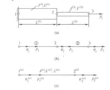
f igure 1. Structure of multi-diameter and its force analysis
B. Discretization
We can support two elements on the two poles respectively. These two elements are connected together by means of node two. So, the whole structure is divided into two elements and three nodes. Only axial displacement can be existed in every element. The three nodes’ displacements are ф р ф > ф respectively.[2]
-
C. Element analysis
The purpose of element analysis is building element stiffness matrices. We have taken the element e for example. When the two ends of element are forced by axial force P ( e ) and P 2( e ) respectively, they have certain relations with the displacements of ф ( e ) and ф ( e ) which lie on the two end nodes 1 ( e ) and 2 ( e ) . According to strength of materials, we can collude that:
p ( e ) _
P1 =
p ( e ) _
P ( 1 ) =
E ( e ) A ( e ) l ( e )
E(e ) A(e ) l ( e )
- ф2 e))
( - ф 1 e ) + ф 2 e ) )
It can be represented by matrix form:
( P 2( e )
P
V P2 V
E ( e ) A ( e ) Г 1 l ( e ) - 1
-
Ж Г
1Аф2 V
The representation is also simplified the following form:
(p)(e) = [к ](e )(ф)(e)
In this formula, ( P ) ( e ) is the node force vector quantity; ( ф ) ( e ) is node displacement vector quantity; [ K ] ( e ) is element rigidity matrix. And the element rigidity matrix can be changed into normal form:
|
, , p ( e ) д(e ) Г^1( e )_ E A |
" EA EA" Г 1 -11 1 Г _Г k 11 k 12 |
|
[ K ] l(6 ) |
[- 1 1 ] - EA EA [ k 21 k 22 _ l l J |
Any element k in the matrix is called element rigidity coefficient. It shows the load in node I area is caused by node j displacement in the element.
-
D. The whole rigidity equation which formed by all elements
In the whole structure, the node displacement and node load vector of three nodes is ( ф ) = ( ффф ) T .
Then we get:
(P )=[к ](ф)
/< к
11 12
k 13
In formula (1), [ K ] =
k 21
k 22
k 23
is called the whole rigidity equation.
k31
k32
к
The main task of whole analysis is solving the whole rigidity matrix. There are two kinds of methods which used to acquire the whole rigidity matrix: one method is that we can get every matrix element directly in accordance with the definition of rigidity coefficient, another method is that we can get the whole rigidity matrix by means of combing method after solving every unit’s rigidity matrix. We accepted the latter one. We should convert every element’s local number into the total number before constructing the whole rigidity. Then we expand element rigidity matrix in accordance with the whole degree of freedom and re-mark the coefficients of original element rigidity matrix in accordance with the total number.
|
[ K F' = |
" k 11 _ k 21 |
k 12" k 22 _ |
( 1 ) 4 K F’ = |
k 11 k 21 0 |
k 12 k 22 0 |
0 " 0 0 _ |
( 1 ) |
|||
|
( 2 ) |
||||||||||
|
k 11 k 21 |
k. 12 k 22 |
( 2 ) |
0 |
0 |
0 |
1 |
||||
|
[ K F1 = |
[ L |
^ [ K F1 = |
0 |
k22 |
k23 |
|||||
|
L 0 |
k32 |
k33 |
J |
|||||||
We can solve the whole rigidity matrix by adding the coefficients with same subscript and arranging them in accordance with the whole coding.
|
" k <1) |
k 1 ( 2 ) |
0 |
|
|
[ K ] = [ K ] • [ K ] (2 ' = |
k 21 ) |
k 22 ) + k 22 2 ) |
к ( 2 ) 23 |
|
_ 0 |
к ( 2 ) 32 |
к ( 2 ) 33 |
-
E. Solving depending on boundary conditions
The boundary condition of the example is the displacement of node one is zero ( ^ j = 0 ). After putting the known data into formula, We can get the whole equilibrium equation by calculating.[3]
|
_ 2 |
- 2 |
0" |
"0 1 |
■ Pi |
||
|
1.96 x 10⁶ x |
- 2 |
3 |
- 1 |
^ 2 |
= |
0 |
|
L 0 |
- 1 |
1 |
_^3 _ |
_ 10 |
We can get the following result by solving formula (3).
^ = 0.255 x10⁻⁵ cm, ^ = 0.765 x10⁻⁵ cm
-
F. Calculation of every element stress and strain
-
3. Discretization in finite element analysis
Strain of every element:
е(1) = ф2 -ф1 = 0.255 х10-6, е(2) = ф3 - ф2 = 0.51x10—6 l(1) ’ l(2)
Stress of every element:
о ( 1 ) = E ( 1 ) е ( 1 ) = 4.998 N / cm 2 , о ( 2 ) = E ^е ( 2 ) = 9.996 N / cm 2
Because the practical mechanical structure is very complex, it is hard to describe in spite of the structure has been simplified. When we analyze mechanical structure, we must choose proper element to match. So the continuous structure can be scatted, which can make the built calculating model near the practical structure. The main problem during the discretization of structure is that choosing element type, classing elements, numbering elements and numbering nodes.
-
A. Rules of choosing elements’ type
When we analyze finite element, whether we can choose unit type correctly is important to make analyzing result precisely. So, we should obey the following rules when we choosing element types.
-
• The chosen element type should be close to geometry of structure well.
-
• The chosen element can reflect the object’s working state. For example, we can ignore the flexural deformation when the machine tool is pressed greatly. We can use plane stress element at this time.
-
• According to calculating precision, we should consider the calculated workload. And we should choose linear element or higher-order element.
-
B. Element type and characteristic
Wind power generator vane’s element: Usually, the constructional element whose section size is far smaller than its axial size is called roll formed constructional element. Roll formed constructional element is always prescribed by means of roll formed element. Roll formed element belongs to one-dimensional element. According to the form of structure, wind power generator vine can be divided into roll element form and beam element form when it is used to analogue roll formed constructional element.
-
• Roll element has two nodes. And every node only has axial degree of freedom. Fig.2 shows this structure. So it can be stressed by axial load. The usual pin-connected truss is processed by this kind of element.
-
• Plane starting element also has two nodes. And every node has such three degree of freedom in plane as transverse degree of freedom, axial degree of freedom and rotary degree of freedom, which are all shown in Fig.2. This kind of element can be stressed axial force and bending moment tangential force. For example, the main axis of machine can be processed by this kind of element.
-
• Space wind power generator vine’s element is the extension of plane wind power generator vine’s element. So, every element’s node has six degree of freedom, which is shown in Fig.2. When the height of beam section is one fifth bigger than its length, we should consider affection of deflection which caused by shear cut, and the usual method is to adjust beam element’s rigidity matrix.
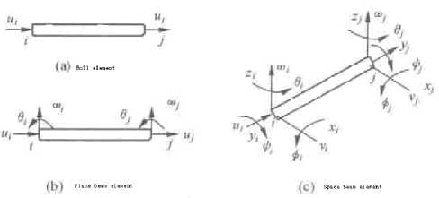
f igure 2. Roll formed element
f igure 3. Plane elements
-
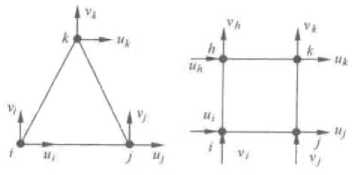
• Thin plate element: Thin plate element is usually defined the constructional element whose thickness is far smaller than its outline size. Thin plate element is mainly used to process thin plate constructional element. On the other hand, it is also used to simplify the load structure of plane problem. This kind of element belongs to two-dimensional element. According to the load ability, it can be divided into plane element, bent element and thin shell element.
Thin plate bent element is mainly stressed transverse load and bending moment of two horizontal axis.[4] It also has one-angle form element and rectangular element form, and they have three nodes and four nodes respectively. And every node has one transverse degree of freedom and two rotary degrees of freedom, which are shown in Fig.4.
f igure 4. Thin plate bending element
-
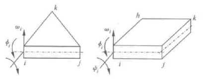
• Multi-plane element: Multi-plane element is the extension of plane element. Fig.5 shows threedimensional element (four-plane element), which has four nodes. Every node has three degree of freedom which alones the three directions of coordinate axis. Multi-plane element can be used to finite analysis of three-dimensional structure. Now, multi-plane element is always used in large-scale finite element analyzing software.
-
• Isoparametric element: Any nodes’ displacement can be solved by means of interpolation computation in finite element method. And the displacement interpolation function is usually called shape function. If any coordinate value in element uses the same shape function to prescribe interpolation in accordance with node coordinate, then this kind of element is called isoparametric element.
-
4. Discrete process
f igure 5. Isoparametric elements
Isoparametric element has so many advantages, and it can be used to simulate any curve or any curved surface. The precision of analyzing or calculating is very high. Isoparametric element has many types, such as the inoparametric element with from four to eight nodes in plane and the inoparametric element with from eight to twenty-one nodes.
After have choosing elements’ type, we can take the discrete process of analyzing model. The analyzing model can be divided into finite elements which are connected by means of nodes.
Before do this, we should determine the number of elements in accordance with calculated precision and computer hardware performance. At the same time, we should pay attention to the following problems:
-
(1) Any crank point in a element must be the crank point of interfacing element. Fig.6 (a) is correct, and Fig.6 (b) is wrong.
-
5. Element analysis
(2)We should try our best to shorten the difference between every two length. There isn’t any obtuse angle should be in triangular element. Fig.6 (c) is correct, and Fig.6 (d) is wrong.
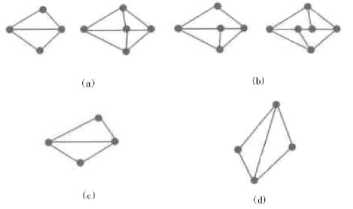
f igure 6. Discretized procession
The purpose of element analysis is building the element’s finite equilibrium equation by analyzing element’s physical characteristic.
-
A. Element displacement interpolation function
After being discretized, we can analyze the elements’ characteristics. In order to use node displacement to express element’s inner displacement and stress, we must suppose the displacement distribution in elements when we analyze the problems about continuous structure. This means that we suppose displacement is a easy function of coordinate which is called displacement inserting function of element.[5]
The key of finite element analysis is choosing proper displacement interpolation function. Displacement function should be near the actual displacement, which can ensure that the calculating result is precise. Displacement function must have three conditions: © Displacement function should be continuous in element,
and the displacement between two interfacing elements should be coordinate. © Displacement function must
includes element’s rigidity displacement. © Displacement function must includes element’s normal strain state.
In the example which is shown in Fig.3. The coordinates of node i, j, k are
respectively. Every node has two displacement components which are
( 8 i) = ( u i
(xi, У1) (xj, yj) (xk, Ук )
Vj ) T . Any node ( x , y )
displacement is ( f ) = ( u V ) T
in element whose subscript is i = i , j , к
For example,
( 8 ) ( e )=( ul v i U j v j uk
T vk ) represents element s node displacement array. We use linear function (4)
as element’s displacement function.
u = ax + a2x + a3y
v = a 4 + a5x + a4y
After using boundary conditions, we can get the following equation:
' u = Niui+ N>j+ Neuk
v = Nev, + Nevi + Nevk ii jj kk
Its matrix form is:
(f ) =
Ne 0
0 N ie
Nej 0
0 Ne k
N ej 0
N ek
(8) \]-,>)(e)
In formula (6), N is the function of coordinate, and it only has relations with element’s form, which is called element displacement form function. Its shorter form is shape function.
-
B. Element rigidity matrix
Element rigidity matrix is determined by element type. And it is deducted from principle of virtual work and variation principle. So the before-mentioned triangle element’s rigidity matrix is:
|
" ket |
k iej |
e kik |
|
|
[ K ] ( - ) = |
k ei |
k ejj |
e k jk |
|
_ k ki |
k kej |
e k kk |
Every element in rigidity matrix has relations with its shape and material’s characteristics which express the node force which caused by element node displacement. Usually, element rigidity matrix has three characteristics: symmetry, singularity and the elements on rigidity matrix’s main diagonal are all positive.
-
C. Building element equation
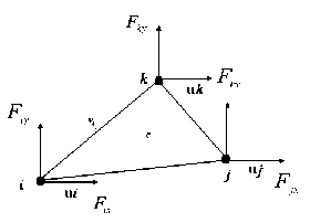
Figure 7. Element’s node force and displacement
The methods which used to build finite element analysis by means of element equilibrium equation include principle of virtual work and variation principle. Now we have taken principle of virtual work for example to explain how to build finite element analysis element equation.
Fig.7 shows the three-node triangle element’s three nodes’ forces are ( Fh , F( ),( Ffx,F )( Fkx,Fk ) respectively. We suppose the node force is the form of ( F ) ( e ).
F(e) = FF F F F. У ix iy jx jy kx ky
So the virtual work which caused by ( F ) ( e ) is W ( e ) = ( ( o e ) ^ ( F ) ( e ) if the virtual displacement in the e ( e ) node is ( o ) .
So the whole element’s virtual strain is:
U(e) = JJJ v (EX + ^X + YeyTxy dv = JJ (Ee )T (^)(e) tdxdy
In this formula, t is the element’s thickness.
From the principle of virtual work, we can get W ( e ) = U ( e ).
So we can draw the conclusion about [ K ] ( e ) ( O ) ( e ) = ( F ) ( e ) which is finite element’s element equation.
-
6. Conclusions
When we analyze finite element, we should obey the following rules when we choosing element types.
-
• The chosen element type should be close to geometry of structure well.
-
• The chosen element can reflect the object’s working state. And we should choose proper surface.
-
• According to calculating precision, we should consider the calculated workload. And we should choose linear element or higher-order element.
Post processing is mainly used to synthesize the analyzing results. We can refine the important conclusion from data analysis. The conclusion can used to check the product design’s legitimacy.
Acknowledgment
We are very grateful to the Jiangsu Province College Natural Science Foundation of China for the support.
References Vane Design Which Based on Finite Element Analyzing Method
- Yu Chunlong, Utilization of Digital Technology in Architectural Design[J], HUAZHONG ARCHITECTURE, 2007 25(9)
- Yu Chunlong, Wu Guobo, Using Lightscape Aided Design of Luminous Environment in Interior[J], NEW ARCHITECTURE, 2006(5)
- Qi Xinmei, Current research situation of mechanical product modeling and its development trend[J], JOURNAL OF HEFEI UNIVERSITY OF TECHNOLOGY, 2000 23(6)
- LIN Yin-da, TIAN Hong-xi, Discussion the hand drawing expression skill new trend in information and digital time[J], SHANXI ARCHITECTURE, 2010 36(14)
- Wei Xiaoming, The research and development on mechanical product model[J], MODULAR MACHINE TOOL & AUTOMATIC MANUFACTURING TECHNIQUE, 2003(5)
