Velocity Feedback Control of a Mechatronics System

Author: Ayman A. Aly
Journal: International Journal of Intelligent Systems and Applications(IJISA) @ijisa
Article in issue: 8 vol.5, 2013.
Free access
Increasing demands in performance and quality make drive systems fundamental parts in the progressive automation of industrial process. The analysis and design of Mechatronics systems are often based on linear or linearized models which may not accurately represent the servo system characteristics when the system is subject to inputs of large amplitude. The impact of the nonlinearities of the dynamic system and its stability needs to be clarified. The objective of this paper is to present a nonlinear mathematical model which allows studying and analysis of the dynamic characteristic of an electro hydraulic position control servo. The angular displacement response of motor shaft due to large amplitude step input is obtained by applying velocity feedback control strategy. The simulation results are found to be in agreement with the experimental data that were generated under similar conditions.
Mechatronics System, Velocity Feedback, Servo Motor
Short address: https://sciup.org/15010452
IDR: 15010452
Text of the scientific article Velocity Feedback Control of a Mechatronics System
Published Online July 2013 in MECS DOI: 10.5815/ijisa.2013.08.05
Hydraulic systems are commonly used in industries where high levels of power and accurate positioning are required to manipulate heavy objects or to exert force on environment. Examples include pick and place robots, positioning of aircraft control surfaces, flight simulators, and heavy-duty manipulators like excavators and feller punchers, hydraulic systems consists of components such as valves, actuators and pumps whose dynamic characteristics are complex, nonlinear and time varying, [1].
The nonlinearity arises from many sources including relationship between pressure and flow, flow deadband and saturation, change of fluid volume in different parts of the stroke, changes in the temperature-sensitive bulk modulus of the working fluid, and directional nonlinearity of the single rod actuator. Other factors that influence the performance of hydraulic functions are friction between moving parts or changes of supply pressure and load, [2, 3, 4]
The modeling of the electro hydraulic components is to be the prime importance factor in the design of electro hydraulic system. In practice it is often difficult to formulate a sufficiently accurate model of an electro hydraulic system, [5].
The traditional approach for designing a controller for a given nonlinear systems is to first linearize the model equations, and then develop the control algorithm using well-established linear control design techniques. Although this method works well for some systems, there are other systems for which a linear model does not provide an adequate description of the actual system and therefore does not produce acceptable controller performance.
Nonlinear analysis techniques (such as Lyapunov method, [6]) do exit for verifying stability; however, these methods generally do not provide any indication of the system performance or how to improve the controller once a stable controller found. Hence, these methods are useful for verifying controllers, but are of little benefit in the design process.
J.M. Finney, etl, [7] implemented an adaptive pole placement controller for position regulation of a single rod hydraulic cylinder. However, since pole assignment schemes adjust only the position of the closed-loop poles, they cannot give good response characteristics for tracking cases.
Richard D. A., etl, [8] presented equations of motion for an electro hydraulic positioning system and experimental applications of the successive Galerkin approximation synthesis strategy to the system under a varying of operating conditions are compared with simulation results. However they used linearized model equations in their simulation.
The main objective of this paper is to present a nonlinear mathematical model which allows simulation and analysis of the dynamic characteristics of an electro hydraulic position control servo system. Also improving the system band width by adding the velocity feedback as a minor loop in the system is successfully implemented. In the dynamic model, two major nonlinearities are considered: (1) pressure/flow characteristics associated with the spool valve, and (2) Coulomb-friction, which is already present or intentionally introduced in the valve motor load. The model includes valve dynamics as well as the effect of oil compressibility and actuator leakage. The dynamic response for the angular displacement of the servo system with position feedback as well as with velocity feedback is obtained.
The remainder of this paper is organized as follows: Section 2 gives the actuator mathematical model. Section 3 describes the used control strategy. Section 4 presents the results and discussions. Conclusion and future work are given in the final section.
-
II. Mathematical Modeling
The closed loop electro hydraulic position control system under consideration is shown in Fig. 1. A two-stage electro hydraulic servo valve is connected to a hydraulic rotary actuator by very short hoses. The closed-loop action is obtained by comparing the angular position of the motor shaft with the input signal by the interfaced circuit. A tachogenerator is used to measure the angular velocity, which can be used as a feedback signal to the input of the servovalve drive amplifier.
The electro hydraulic valve consists of a first stage nozzle-flapper valve, and a second-stage 4-way spool valve. The valve drive amplifier has a gain of 100 mA/V.
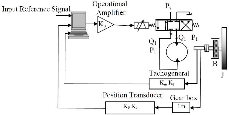
Fig. 1: Schematic Diagram of the Servosystem
The model is derived on the assumption that an inertially loaded rotary motor is controlled by the electro hydraulic servo valve. The steady-state valve model can be represented by the following relation, [9].
dQт — + Q dt
Q = K x V x sgn
1 - ( sgn Vx ) P" , . s J 1
P
1 -( sgn V x )у
P.
K x V x sgn 1 — ( sgn V x )у _ s
P
1 — ( sgn V x ) у s
with
V + B when V < -в
x
The hydraulic motor is modeled by considering the rotary motor arrangement shown in Fig. 1, as well as by taking into account oil compressibility and leakage across the motor. Using the principal conservation of mass yields
V — B when V > -в
The dynamic performance of the servo valve is described by a first-order time lag and is given by:
de vc dp dt 4K dt
The equation of motion of the load can be given by
т dQ dt
xx
PLVm = Jd2e + Bde + Tc sgn e dt 2 dt
Equations (1) and (2) are combined to yield a dynamic valve model as
-
2.1 State Space Model
Definitions of the state variables and inputs of the system are given below:
States:
[ x i x 2 x з x 4 ] = 0 (t ) 0(t ) P l ( t ) P L ( t )
Inputs:
Applying the states definition to the system of nonlinear (1-5), after manipulation, results in the state variable model as follows:
X1 = x2
X 2 =-- X , +--- X,-- Sgn X, J 2 J 3 J 2
X 3 = x 4
.
X 4 = - Xj
+ X2
— X 3
+
4Kh KXKak9ks
T V c
4 K h
T V c
n
tVB
4 K h V m 2 JV c
4Kh tV
I x'u
- V - m
4 K h L e
T Vc
. u 2
—
1 4KhLe
.T Vc
X„
JVc c 2
The state variables model represented by (6-8) is of the nonlinear form
The initial conditions of the state variables are given by:
The parameters of the system appearing in the statevariables model are given in Table 1. The experimental work was carried out at the Automatic Control Laboratory of Assiut University, Egypt.
Table 1: System physical Parameter
|
T |
valve time constant |
s |
2.3x10⁻³ |
|
K a |
operational amplifier gain |
-1 |
|
|
K x |
valve flow gain at P l = 0 |
m3/s/v |
-1.36x10⁻⁴ |
|
V c |
volume of hoses |
m3 |
20.5x10⁻⁶ |
|
V m |
motor displacement |
m3/rad |
0.716x10⁻⁶ |
|
L e |
leakage coefficient |
m5/Ns |
2.8x10⁻¹¹ |
|
K h |
hydraulic bulk modulus |
N/m2 |
1.4x10⁹ |
|
B e |
viscous coefficient |
Nms/rad |
2.95x10⁻³ |
|
J |
motor inertia |
Nms2/rad |
3.4x10⁻³ |
|
T f |
coulomb-friction |
N.M |
0.225 |
|
K t |
tachogenerator constant |
v/rad/S |
0.026 |
|
K s |
position transducer constant |
v/rad |
3.44 |
|
n |
gear ratio |
7.5 |
-
III. Structure of Control System
The control valve, which is a standard type 32- Moog servovalve, is connected to a A084 nine-axial piston Moog-Donzelli hydraulic motor. The feedback action is implemented by using a tachogenerator and a position transducer to measure the shaft speed and position.
A synchronal error channel was used to sense the position of the hydraulic motor shaft, compare it to the input signal and derive an error signal. This forms the major feedback loop which is described as:
e,( t) = V, (t) - K-K6/n
The velocity feedback is generated by using a tachogenerator which derives a voltage signal and feeds it back to a differential amplifier, thus forming the minor loop. This action is given by:
e2(t) = -KmKt 0
At first a single control loop is applied. A proportional controller is adopted for controlling the motor position with a step input, whereas the controller is defined by the following equation:
I = K Ke,(t)
pa 1
In order to improve is dynamic response two loops are adopted, the minor feedback loop is formed by applying a tachogenerator to measure the motor speed and generate a feedback signal. On the other hand, a position transducer is adopted to measure the position and use the generated signal to form the major loop, which contributes significant damping effect to the system, whereas the controller is defined by the following equation:
I = Ka, (Kpei (t)+ K^e2 (t))
-
IV. Results and Discussions
The first step in control system design is to obtain the mathematical model, which, describe the dynamics of the plant to be controlled. More accurate dynamic model of the plant led to better control system performance.
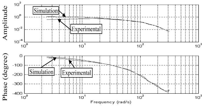
Fig. 2: System bode diagram for the Experimental and Simulation
To simplify the estimation of the model parameters, a closed-loop identification scheme is used. The simulated model bode diagram is presented in Fig.2, and it has good agreement with the experimental one.
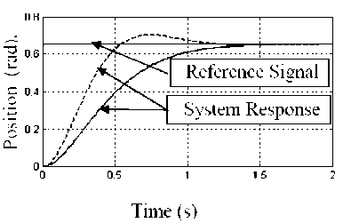
Fig. 3: System step response based on P-controller action
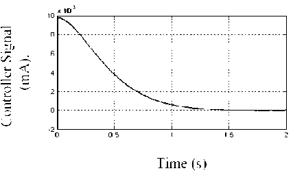
Fig. 4: P-controller action signal
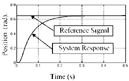
Fig. 5: System step response based on PD-controller action
0.8
Time (s)
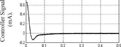
Fig. 6: PD-controller action signal
The desired response is designed without either overshoot or steady state error with smaller rise time as possible. The simulations were performed with a constant supply pressure of 70 bar connected to a hydraulic rotary motor in two different closed loops. Fig. 3 obtained by comparing the input step signal with the synchronic error channel which perform single control loop (P-control), it is found that the rise time is about 1.5 sec. with no overshoot and steady state error is zero. However, if we improve the response rise time an overshoot appeared. Its corresponding control action is shown in Fig. 4.
The other applied with velocity feedback in addition to the position feedback, while the rise time is improved to be 0.3 sec., the overshoot kept to be zero as shown in Fig. 5, and the corresponding control signals is cleared at Fig. 6.
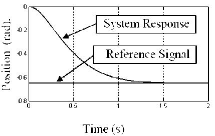
Fig. 7: System step decrease response based on signal P-controller action
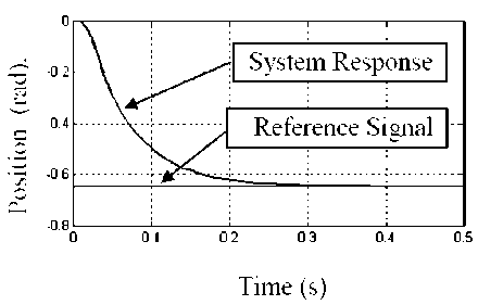
Fig. 8: System step decrease response based on signal PD-controller action
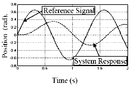
Fig. 9: System sin input response based on signal P-controller action
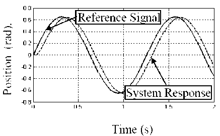
Fig. 10: System sin input response based on signal PD-controller action
Results presented so far in this paper are obtained with a step increase in the reference position. It is of interest to obtain the system response due to a step decrease in speed, in order to throw more light on the complicated role played by motor dry friction. The transient response of the system due to a step decrease in the reference position from 0.0 to -0.65 amplitude is displayed in Fig. 7 and 8 for the motor proportional control loop and for velocity feedback control loops together, respectively.
Another good application with sinusoidal input signal as a continuous motion can test the following ability with the control loops is shown in Figs. 9 and 10.
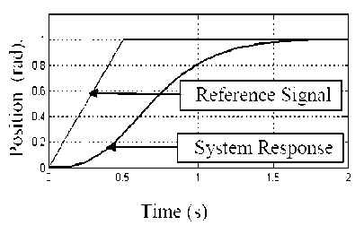
Fig. 11: System ramp input response based on signal P-controller action
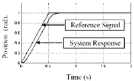
Fig. 12: System ramp input response based on signal PD-controller action
The ramp input is used in many applications, such as for tape drives of cutting tools. In order to follow such a command input, the controller must be able to deal with both step and ramp commands (the step command corresponds to the constant speed). In Figs. 11 and 12 the response of system due to ramp input. It is completely clear that the system response has been improved by using velocity feedback control strategy.
-
V. Conclusions
The dynamic response of a Mechatronics speed control servo system was analyzed in order to throw more light on the complicated role played by the actuator nonlinearities. The following conclusions are derived from the experimental and simulated results:
-
> Good agreement in the system responses due to the random input which clear the precision of the simulated mathematical nonlinear model.
-
> Using different input signal prove that the velocity feedback loop in addition to the position feedback signal gave better dynamic response.
-
> Applying intelligent control system for positioning the electro hydraulic servo motor is under study as a promise target of our work.
Nomenclature
B viscous damping coefficient, N.m.s/rad
Bc Coulomb-friction coefficient, N.m.s/rad
B e viscous damping coefficient, N.m.s/rad
J load inertia, N.m.s2/ra d
K A transfer function gain
K a operational amplifier gain
Kh bulk modulus of fluid, N/m2
Kp valve pressure gain, m5/n.s
Kx valve flow gain at Pl = 0. m3/s/v
Ks position transducer constant, V/rad/s
K t tachogenerator constant, V/rad/s
K θ position feed back gain
K ω velocity feedback gain
Le equivalent leakage coefficient, m5/N.s n reduction gear ratio
P 1 ,P 2 pressures at actuator ports , N/m2
P L load pressure, N/m2
Q1,Q2 inlet and outlet flow of the actuator, m3/s
Q mean flow rate, m3/s
S Laplace operator t time, s
Tc coulomb -friction, N.m
Vc volume of oil in motor and hoses, m3
V i input voltage to the system, V
V m motor displacement, m3/rad
V x valve drive voltage, V
Greek Symbols
τ valve time constant , s
θ shaft position , rad
ω angular frequency , rad/s
References Velocity Feedback Control of a Mechatronics System
- Merritt E., Hydraulic Control Systems, John Wiley, New York, 1976.
- Ayman A. Aly, Aly S. Abo El-Lail, Kamel A. Shoush, Farhan A. Salem,” Intelligent PI Fuzzy Control of An Electro-Hydraulic Manipulator,” I. J. Intelligent Systems and Applications (IJISA),7,43-49,2012.
- Ayman A. Aly, "Model Reference PID Control of an Electro-hydraulic Drive" I. J. Intelligent Systems and Applications (IJISA), 11, 24-32, 2012.
- Fitzsmimons P. and Palazzolo J., Modeling of a one degree of Freedom Active Control Mount, Journal of dynamic Systems Measurements and Control, 118, PP 439-448, 1997.
- Abo-Ismail and A. Ray., Effect of Nonlinearities on the Transient Response of an Electrohydraulic Position Control Servo, J. Fluid Control, Vol. 17, Issue No.3, PP. 59-79, 1987.
- Efim R. and R Yusupov, Sensitivity of Automatic Control Systems, The CRC Press Control Series, Washinton, D.C., PP 52-59, 2000.
- J. M. Finny, A de Pennington, M. S. Bloor and G. S. Gill, A Pole Assignment Controller For an Electrohydraulic Cylinder Drive, Journal of dynamic Systems Measurements and Control, 107, PP 145-150, 1985.
- Richard D. A., Timothy W. M. and Randal W. B., Application of an Optimal Control Synthesis Strategy to an Electrohydraulic Positioning System, Journal of dynamic Systems Measurements and Control, 123, PP 377-384, 2001.
- J. Watton., Fluid Power Systems Modeling, Simulation, Analog and Microcomputer Control, Prentice hall Tokyo, 2002.
