A formal model for legacy system understanding

Author: A.Sivagnana Ganesan, T.Chithralekha, M. Rajapandian
Journal: International Journal of Intelligent Systems and Applications @ijisa
Article in issue: 10 vol.10, 2018.
Free access
Migration of legacy system is not a single step activity but a process that comprises of several phases of which Legacy System Understanding (LSU) is the first step. The intent of this work is to carry out a detailed study on the Legacy System Understanding in terms of Techniques and Tools used and to identify the potential gaps in them. The understanding of the legacy system has to be at the perspective of system level rather than the code level which has a narrow perspective, because the migration at code level may have a cascading impact to different aspects of the Legacy System. These findings have enabled us to formulate a process for building up an artefact repository and artefact dependency repository. These repositories along with the legacy system have aided us in understanding the legacy system in a comprehensive manner in terms of migrating artefacts in the context of migration of legacy systems. A formal mathematical model for representing the status of LSU and application of the same on a case study has been presented.
Legacy System Understanding, Artefacts, Reverse Engineering, Migration, Formal Model, Legacy Systems
Short address: https://sciup.org/15016533
IDR: 15016533 | DOI: 10.5815/ijisa.2018.10.04
Text of the scientific article A formal model for legacy system understanding
Published Online October 2018 in MECS
Migration of Legacy systems is one of the approaches of legacy systems modernization, the other approaches being replacement, re-engineering or redevelopment and wrapping [1]. Migration is not a single step activity but a process that comprises of several phases [2]. Legacy System Understanding is the first phase of the entire migration process and is important because the result of this phase is vital to conduct the migration feasibility assessment, a decision making phase. Moreover, the importance is also due to the fact that the assets embedded in the legacy system viz., business logic and legacy functionality, documentation in terms of code, architecture, database etc. Several Tools and Techniques have been used by the research community towards an understanding of the Legacy System.
Even though many of the papers have discussed the use of tools and techniques of Legacy System Understanding, the significance and comprehensiveness are found lagging in the current literature. Hence this paper entails a consolidation of these works on the tools and techniques of the Legacy System Understanding. Further, through a comprehensive approach, we have explored the Legacy System in detail which has enabled us to formulate a comprehensive list of artefacts and the dependencies among them in the context of Migration of Legacy Systems. The rest of the paper is organized as follows viz., the section II covers the background information, section III briefs about the LSU, its tools and techniques, section IV covers about the findings, section V about the Artefacts Repository, Artefacts Dependency Repository through a LSU Model, section VI about formal mathematical model of LSU, chapter VII about case study and section VIII about the conclusion.
-
II. R elated W orks
Legacy Systems working in a silo and having hardware and software restrictions are difficult to maintain in the changing technological and business environments. Modernization forms an important phase of Information system Life Cycle and Migration is one of the ways to modernize legacy systems, the others being the replacement, re-engineering or redevelopment and wrapping. Migration can be a combination of Language or Code Migration, Operating System Migration, data migration, User Interface(UI) migration, Architecture migration, System software and Hardware migration or migration of any of these individually[2]. Migration is not a single step activity but a process that comprises of many phases. J. Bisbal et al [3] and Khadka et al [4] have provided the phases of migration in their works. The consolidation of the various phases of migration from the above works are Legacy System Understanding (LSU), Target System Understanding (TSU), Migration Feasibility Assessment, Target System Development and Deployment and Provisioning of Target System.
-
A. Legacy System Understanding (LSU)
The understanding of the source code and structure of the data of the legacy systems are essential to all migration projects. In this phase, a detailed analysis of the Legacy system is carried out with the techniques of reverse engineering, program understanding and architecture recovery. J.Ransom et al [5] in their work have used an assessment method to gain an adequate depth of understanding from the technical, business and organizational perspective.
-
B. Target System Understanding(TSU)
The desired architectural representation of the target system is facilitated in this phase. This phase describes the target environment comprising of activities such as defining major components/functionalities of the environment, specific technologies and standards to be used and the state of the target system.
-
C. Migration Feasibility Assessment
The understanding of the legacy system and the target system help in undertaking the feasibility assessments at technical, economical and organization level. The code complexity in technical feasibility and cost-benefit analysis in economic feasibility can be included in the assessment.
-
D. Target System Development
The Target system is developed for the requirements specified which were arrived based on the phases of LSU, TSU and Migration Feasibility Assessment. Program slicing, concept slicing, graph transformation code translation, model-driven program transformation, screen scraping, code query technology etc [4] are used for extracting the legacy code as services to be incorporated in the target system.
-
E. Deployment & Provisioning of Target System
-
III. L egacy S ystem U nderstanding (L su ) S urvey
Legacy system understanding [3] is a core part of migration which is crucial to any successful evolution exercise. The understandings of the source code and structure of the data are vital for any migration project. LSU is required for migration of an old legacy system to new target environment and the success of the migration lies in the understanding of the legacy system functionalities and its interaction with its domain. R.Khadka et al [4] have referred it as as-is analysis of the existing legacy systems which enables a better understanding of technical and functional characteristics of legacy systems. M.Srinivas et al [5] has proposed various techniques for understanding Legacy systems in existence. LSU is a deductive process [6] of acquiring knowledge which aims at acquiring information which includes characteristics of the source code, their dependencies and architecture recovery. This phase of migration not only provides assistance in inventory creation on the existing features but also facilitates decomposition of the Legacy System with the intent of maximizing reusability.
In this paper, the Techniques and Tools that have been applied/deployed by the research community in the LSU have been covered. The intention of this survey is to get an insight into LSU about the extent of the coverage of its constituents and to explore the one that has been uncovered. The next subsections will be covering the Techniques that have been applied for LSU and the Tools deployed in LSU.
-
A. Legacy System Understanding Techniques
Researchers have applied several techniques for understanding the legacy system in the context of migration. The techniques surveyed have been classified and are as shown in Fig. 1.
The LSU techniques can be broadly classified as Code availability based Techniques and Non-Code Availability based Techniques. The techniques under Code Availability based Techniques depend on source code and can be applied to the legacy systems for which source code is very much available. Not all the time source code will be available for older legacy systems. For these systems, the Non-Code Availability based Techniques can be applied. Each and every technique has a focus area and has an outcome associated with it. Here since these are LSU Techniques their primary intent and the focus area is to understand the legacy system as a whole. The outcome associated with each and every technique is tabulated and shown below in Table 1.
-
B. Tool Support for Legacy System Understanding
There are two categories of tools that have been in use for LSU, out of which one set of tools analyses the code with the intended outcome and the other set of tools is to analyse the data with a corresponding outcome. The classification of the tools can be seen in Table 2 which has been carried out based on their support for analysis of Code or Data in the context of LSU. Some of them are specific tools with particular intent whereas others have been developed for catering the particular requirements confined to the approach of the researcher. The tools range from Reverse engineering of source code to extracting knowledge from existing documentation and reconstructing it thereon. Document reconstruction is generating documentation. There are tools for data separation, static analysis reverse engineering, static view extraction, dynamic view extraction, undocumented dependencies in the source code, architecture reconstruction which are listed in Table 2 along with few other tools.
Table 1. LSU Techniques
|
Classification |
Techniques |
Outcome |
Representation of Outcome of LSU |
|
Non-Code Availability based Techniques |
Interviewing[7][8] |
of legacy system |
Informal Model |
|
Documentation (technical document ,design document, FRS, User manuals, etc)[9][10] |
|
Formal model |
|
|
Domain Analysis [11][12] |
|
UML |
|
|
Portfolio Analysis[7], [13], [14][15] |
of the legacy system are built |
Chi-square chart |
|
|
Design Pattern Detection[16] |
• Information about organization and design of the system |
UML |
|
|
Database understanding |
• Graphical representation of database/file schemas |
Graphical |
|
|
Code Availability based Techniques |
Source Code Analysis[17] |
features and extracting various software metrics |
Control Flow Graph Dependency Graph Call Graph |
|
Reverse Engineering[4], [6][18] |
abstraction |
Dependency Graph |
|
|
Clustering[19] |
• Reusable legacy code segments |
Directed State Transition Graph |
|
|
Program Understanding[20][21] |
• Functional and data concepts of the program |
Control Flow Graph |
|
|
Architecture recovery[7][22]-[25][26][27] |
• Architectural Information/views of legacy system |
Class/ Interface Relationship Graph(CIRG) Class/ Interface Dependency Graph(CIDG) |
|
|
Data Flow Analysis[28] |
• Information to find Values of variables/data at various stages of the program |
Type Graph |
|
|
Program Analysis[29] |
• Identification of legacy components |
Control Flow Graph Data Flow Graph Structure Charts |
|
|
Code Annotation[28] |
• Information from programs |
Type Graph |
|
|
Feature Location Technique[30] |
• Functional Units of source code |
Tree |
|
|
Dynamic Analysis[23], [31][35] |
of the software behaviour |
Process Graph |
|
|
Functional Analysis[4], [8] |
• Functions to be exposed as services |
Function List |
|
|
Function Mining[36] |
• Reusable Functions along with data from program |
Procedural Graph |
|
|
Source Code Visualization[6][37] |
• Source code and their dependencies |
Directed Graph |
|
|
Source Code Modelling [24] |
• Data models from source code |
Class/Interface Relationship Graph(CIRG) Class/Interface Dependency Graph(CIDG) |
|
|
Static Analysis[23], [31], [35] |
• Static information describing the structure of the software |
Graph Repository |
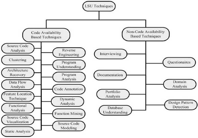
Fig.1. Classification of LSU Technique
-
IV. F indings of the S urvey on LSU
Based on the study conducted in the previous section on Legacy System Understanding, some of the tangible outcomes of LSU are listed below:
-
• Business Rules(Logic) Extraction
-
• Static data analysis
-
• Behaviour analysis
Identification of components of the system and their dependency
Representation of systems in another form or at a higher level of abstraction
Inventory creation of features
Decomposing facilitation
Architectural views extraction
Design recovery .
Table 2. LSU Tools
|
Classification Type |
Tool |
Intent |
|
Code Analysis |
Software Refinery |
Reverse Engineering Tools Generator and it supports platforms of Sunsparc; HP 9000/7xx; IBM RS/6000. |
|
Jude |
Static view extraction – Extraction and diagram manipulation |
|
|
Omando UML Studio |
Static view extraction – Generate Package diagram |
|
|
Eclipse TPTP |
Dynamic view extraction - extract runtime information |
|
|
ARMIN |
Identification of undocumented dependencies in source code |
|
|
E-BUS Toolkit |
Architecture reconstruction for various java based systems |
|
|
Understand |
explore features, functional dependencies and compute various metrics |
|
|
Imagix 4D |
A comprehensive program understanding tool for C and C++ programs. |
|
|
Rigi |
Assists in structural re-documentation of source code and it supports platforms of Sunsparc; IBM RS/6000; Pentium PC and supports viewing of parsed C, C++, PL/AS, COBOL, and Latex code and language-independent tools. |
|
|
Data Analysis |
Tools by Companies |
IBM, Compuware, Intersolve, Microfocus, Bachman have developed tools that isolate the data information in COBOL applications. |
|
Bachman Re-engineering Product Set |
Focus on recapturing the physical database designs semantics. |
|
|
Software Code Interviewer(SCI) |
Static analysis reverse engineering tool with the intent of discovering data model from COBOL source code and Job Control Statements. |
|
|
DBMAIN |
Is a graphical, general-purpose, programmable, CASE environment, dedicated to database application engineering and focus on recapturing the physical database designs semantics. |
|
|
Seedata |
Relational legacy database structure representation using computer graphics. |
|
|
Refine/C |
to understand, evaluate, and re-document existing C code. |
Most of these are the outcome of the source code analysis/data analysis. Similarly, most of the tools and techniques discussed in Table 2 have one way or other associated or depended only on the source code. However, an understanding of the legacy system has to be at the perspective of system level rather than the code level which has a narrow perspective, because the migration at code level may have a cascading impact to different aspects of the Legacy System. For example, migration of code from one platform to another platform may require a migration of Operating System also and migration of operating system may in turn cascade down to migration of hardware. Hence a holistic understanding of Legacy System at system level regarding their assets and artefacts (commonly referred as a piece of hardware or software or documentation) is a strong necessity from the migration perspective.
In order to attain this understanding, it is very important to identify the possible migrating artefacts present in a Legacy system and their dependency with each other to be represented as an outcome of the Legacy System Understanding, which is an essential requirement. It is evident from the study conducted on LSU that, the status representation of the Legacy System which is the outcome of Legacy System Understanding is an essential part missing or not properly addressed in the literature surveyed by us. Moreover, this survey also reveals that a formal model to represent the understanding of Legacy System with respect to migrating artefacts that could possibly migrate and their dependency with other migrating artefacts of the Legacy System is yet a white space to be addressed. Our proposed approach for Legacy System Understanding process is explained which addresses the above mentioned gap.
-
V. P roposed A pproach T o L su
Our Systems approach to LSU tends to visualize a legacy system as comprising of artefacts. An Artefact is commonly referred as a piece of Hardware or Software or Documentation [38]. In this paper, we focus on the Hardware and Software artefacts only. These artefacts reside in the different layers of the legacy system. For eg., a typical legacy system can be composed of the layers as shown in Table 3 below.
Each of these layers would have its own IT artefacts. For eg. significant artefact in the Hardware Layer is the Processor. The System Software Layer may be composed of the operating system, other system software like compilers, network software etc. The middleware layer would comprise of middleware software. The business logic of the application running in the legacy system is present in the Business logic layer.
Finally, the UI layer has the interface code running in it. The artefacts in these layers communicate with each other to constitute the functionality of the legacy system. Thus going by this systems approach for LSU, it is essential to provide with a standard set of artefacts that may be used to describe a legacy system. A definition of the number of layers in the legacy system and mapping the identified artefacts to the same provides an organized view of legacy systems.
-
Table 3. Layers of a Legacy System
Layers UI Layer Business Logic Layer Data Access Layer Middleware Layer System Software Layer Hardware Layer
Since the LSU is primarily to study the legacy system which is to be subjected to migration, the relationship between the artefacts in the different layers also needs to be identified so that, it is easy to understand the artefacts which are impacted by a migrating artefact to decide whether they too have to migrate for compatibility or portability reasons. Thus our approach to LSU requires performing the following:
-
1) Identification of IT Artefacts that could possibly migrate in Legacy System and construction of Artefact repository.
-
2) Identification of dependency between Artefacts and construction of Artefact Dependency repository.
The Application of the artefacts and their dependencies on candidate legacy system and formally representing the same would result in our proposed system view of LSU. In the description below, we explain how the artefact repository and artefact dependency repository are to be constructed.
-
A. Artefacts Repository
For any migrating Legacy System, the entities to be focused upon are the IT Artefacts that could possibly migrate. The migrating artefacts of the legacy system have to be identified for the legacy system understanding. For this purpose, one has to conduct a detailed study of various legacy systems (i.e.) migration applications for identification of migrating artefacts. In this regard, representative applications for each of the milestones in the formulated Migration Evolution Roadmap have been taken up and migrating artefacts in each have been identified. This road map has been formulated by us in our previous work [2]. The various platforms in every milestone of evolution roadmap and the application considered for study in each are given in Table 4.
The study and in-depth analysis of the above systems have given a holistic understanding about the constituents of the legacy system. The study has been conducted in terms of the following components of the Legacy System viz., Source Code, Middleware, DBMS, System Software and Hardware. Further, the systems have also been explored in terms of their application architecture both on single system deployment and multiple system deployments. Artefacts of the migrating systems identified using the above representative application systems are classified broadly as stated below:
the legacy system. The primary artefacts identified are
-
• Implementation Artefacts
-
• Documentation Artefacts
Table 4. Platforms and Application Systems
|
Platforms |
Selected Application Systems |
|
Mainframe |
Credit Card Processing System |
|
Micro/Mini |
Demand Collection Balance System |
|
Client-Server – Fat Clients |
Financial Accounting System |
|
Client-Server Thin Clients |
|
|
Multilayered Systems |
ERP Systems Core Banking Systems e-Governance Systems |
|
Multilayered Distributed Systems |
|
|
Multilayered Composable Services Systems |
|
|
Multilayered Virtual Systems |
The artefacts identified may not be exhaustive but necessary and sufficient to represent the understanding of
-
• Source code
-
• DBMS
-
• Middleware
-
• System Software
-
• Hardware.
Secondary Artefacts are the ones that have been found by exploring the primary artefacts. The identified migrating artefacts have been represented in a tree form in Fig. 2. In this work, the focus is confined to the Implementation artefacts.
The primary artefacts and secondary artefacts thus identified and represented in Fig. 2 have been listed below:
-
• Source Code
-
- User Interface
-
- Database
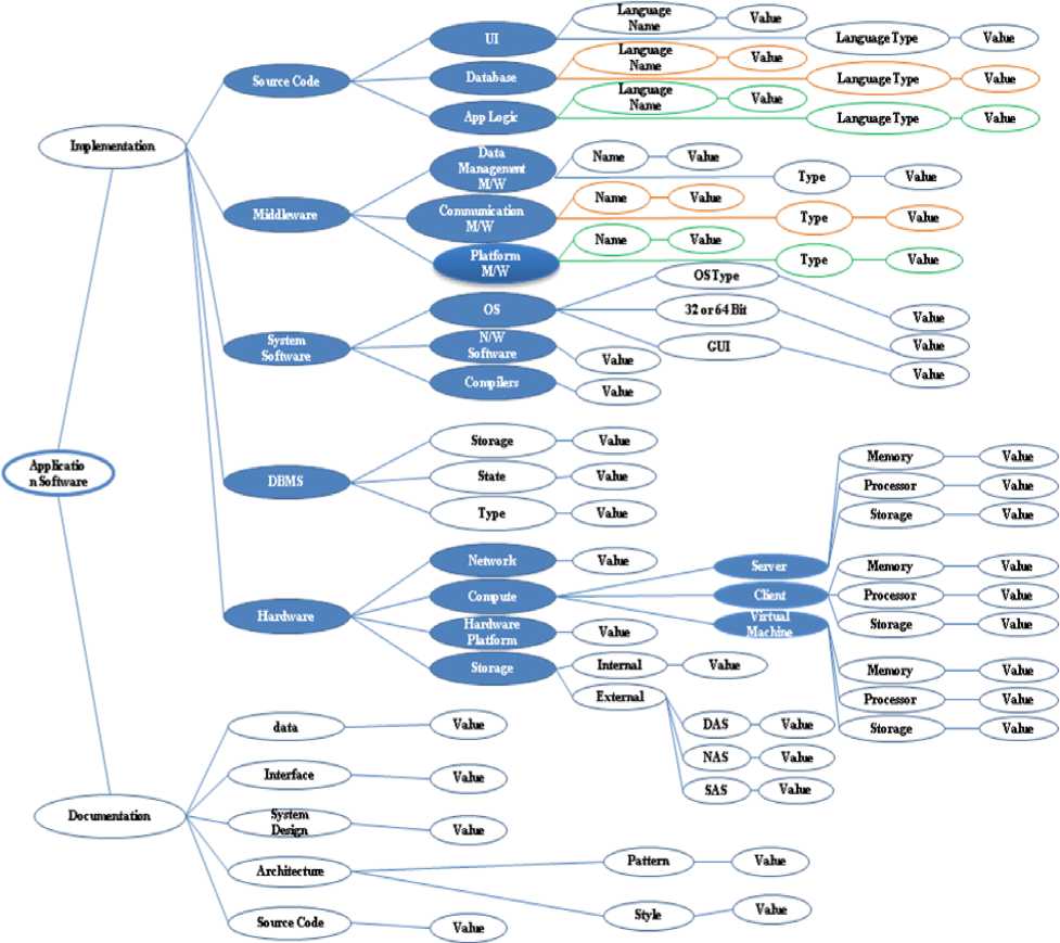
Fig.2. Migration System Artefacts
-
- Application Logic
-
• Middleware
-
- DataManagement Middleware (ODBC, JDBC, OLE, NFS)
-
- Communication Middleware(CORBA,RPC,JMS) - Platform Middleware (J2EE, DOT NET, Customer Information Control System)
-
• System Software
-
- Operating System
-
- Networking Software
-
- Compiler
-
• DBMS
-
- Storage
-
- State
-
- Type
-
• Hardware
-
- Network
-
- Compute
-
- Platform
-
- Storage
The evolutions of legacy systems are dependent on its decomposability. The evolution becomes difficult when the decomposability is less.[4]. According to the decomposability of a legacy system, the architecture of a system can be decomposable, semi decomposable, or non-decomposable. A software system usually comprises of the components of user interface, application logic and database. In decomposable systems, all the above three types of components are separable. In case of semi-decomposable systems, the user interface is separate, whereas the application logic and database are together and cannot be separated. The Non-decomposable systems are the ones where all the three types of components are inseparable and the system is a black box. Hence, the secondary artefacts of the source code have been identified as user interface, database and application logic. The name of the language in which the source code is developed and the type of the language such as procedural, object-oriented etc are the attributes of these secondary artefacts.
The Middleware Artefact is composed of three type of middleware viz., Data Management Middleware, Communication Middleware. Data management middleware functionality helps programs including application programs and DBMS read from and write to remote databases or files. Eg. Network File System (NFS), ODBC, JDBC, OLE. Communication middleware helps programs talk to other programs. It is software that supports a protocol for transmitting messages or data between two points as well as a system programming interface (SPI) to invoke the communication service. Eg. RPC, CORBA/IIOP, JMS. Platform middleware provides the runtime hosting environment (a container) for application program logic. Eg. J2EE or .NET Framework/COM+.
As far as DBMS is concerned, the various database models, kinds of database and how they are stored have been studied. This study has aided us to identify the relevant secondary artefacts viz., DBMS State, DBMS
Type and DBMS Storage. The state of the DBMS can be either embedded or federated. The type of DBMS can be Relational, Hierarchical, Network and Object Oriented. The DBMS can be stored locally or in a remote location or can be replicated.
The secondary artefacts of the System Software have been identified as Operating System, Network Software and Compilers because of the following. The source code uses a compiler/IDE for the application to run on the designated Hardware which has an operating system associated with it. The communication between the systems in case of multisystem deployment requires a network and the associated software.The Hardware comprises of the artefacts of Compute, Storage, Networking Hardware and Hardware Platform. The Compute could be a Client or Server or a virtual machine. The storage could be a Direct Access Storage (DAS) or a Network Access Storage (NAS) or Storage Area Network (SAN).
The Hardware Platform could be x86, IA-64, VAX, S/60 etc. The identified migrating artefacts are to be stored in a repository and the formal model of an instance of the Legacy System has to be represented in terms of these identified primary and secondary artefacts
-
B. Artefact Dependency Repository
The next important building block in the legacy system understanding is the dependency among these migrating artefacts. The artefact dependency repository is a collection of information on the possible dependencies with one migrating artefact to the other migrating artefacts in the artefacts repository.
The dependencies among the migrating artefacts play an important role in the migration of legacy system understanding process. This is because the change due to the migration of one artefact can impact not only the immediate depending artefact but can have a cascading effect on the further depending artefacts also.
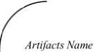
Inter and intra dependency among the artefacts have been analysed and explored. They have been identified as primary and secondary. The intra dependency is the dependency between secondary artefacts of a primary artefact. Eg. the dependencies between Operating System, Compiler and Networking Software in the System Software primary artefact. The inter dependency is the dependency between secondary artefacts of primary artefacts with secondary artefacts belonging to the other primary artefacts. Eg. The dependency of Operating System of System Software primary artefact with that of Platform and storage of Hardware primary artefact. The dependency between artefacts A and B have been categorised as Singular Dependency and Dual Dependency. Singular Dependency between A and B implies that if Artefact A is changed due to migration, it impacts Artefact B. If the reverse is also true in addition to the above, it implies a Dual Dependency. Every primary artefact is taken and dependency with every other primary artefact has been identified. Similarly, the dependency between each and every secondary artefact with every other secondary artefact is explored and identified. The dependencies among the artefacts thus identified have been depicted in Table 5 below. The dependency repository captures the default dependencies between the artefacts in a system, but may not be an exhaustive set of dependencies as certain dependencies may vary in different candidate legacy systems and need to be captured/updated accordingly
The dependency between same artefacts either primary or secondary is not an applicable dependency. These artefact dependencies are to be stored in a repository named Artefact Dependency Repository which is another important repository in the Legacy System Understanding.
The analysis of a typical instance of a Legacy System in terms the identified artefacts and their dependencies as stored in two repositories respectively can help in representing the outcome of the LSU carried out on a legacy system.
Table 5. Artefacts Dependency
|
Artefacts Name |
ф £ ф 8 8 |
СО |
ф « ф X 2 |
£ Е ф и х о. 35 |
II |
£ 2 U |
£ ф 5 ■о Ё |
Е |
|
|
Source Code |
|||||||||
|
DBMS |
|||||||||
|
Hardware |
И№И: |
||||||||
|
Network |
|||||||||
|
Compute |
|||||||||
|
H/w Platform |
। m ini |
||||||||
|
Storage |
|||||||||
|
System Software |
|||||||||
|
OS |
|||||||||
|
N/w S/w |
ш |
||||||||
|
Compilers |
|||||||||
|
Middleware |
|||||||||
|
M/w Platform |
|||||||||
|
■■ Primary Artefacts |
Secondary Artefacts Not Applicable |
||||||||
-
C. Application of Artefacts and their dependencies on Candidate Legacy Systems
Using the artefacts stored in the artefact repository, the understanding of a candidate legacy system needs to be performed.
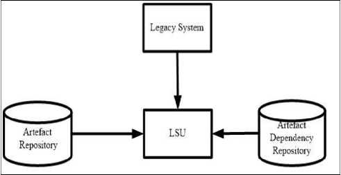
Fig.3. LSU Model
The relationship between the artefacts also needs to be captured from the legacy system using the artefact repository. Thus, the artefact repository, artefact dependency repository and application on a candidate legacy system for its understanding constitutes for our proposed System model of LSU as shown in Fig. 3.
In order to represent the understanding of the legacy system in terms of our identified artefacts, a formal mathematical model as described in the next section is proposed by us.
-
VI. F ormal M athematical M odel of LSU
The deployment of legacy systems can be deployed as a Single System Deployment or Multi-System Deployment. In Single System Deployment the entire application will be running on a single standalone system. The Multi-System deployment is the one where the deployment spans across systems. Hence the identified artefacts and their dependencies have been formally represented viz., Single System Deployment and Multisystem Deployment of legacy system.
-
A. Single System Deployment (SSD)
Single System Deployment is a five tuple
( L,A,C,RLA,RAA) Where
L represents Layers of the Legacy System
A represents Artefacts
C represents Communication between Layers
RLA Relationships between Layers & Artefacts is which artefacts are in which layer.
RAA represents Relationships Among Artefacts
Definition 1: LAYERS
L = (L(i) | i = 1 to NL where NL = Number of Layers) /*The NL Layers, L, is identified*/
Table 6. Operations on Layer
|
Possible Operations on Layer definition for artefacts |
Functionality |
|
ADDLAYER(l,b,a) |
Add Layer l |
|
SWITCH_LA( i: {1.2.,,NL}; a :String; val: {0,1} ) |
Switch/Change the values of Arefacts in a particular Layer |
Definition 2: ARTEFACTS
A = {x| x is an artefact};
/*The set of artefacts, A, is identified*/
NA = |A|
/*NA = Number of artefacts in A*/
NG = Number of grouping of artefacts
AG = (AG(i) for i = 1 to NG)
/*NG groupings of artefacts are identified*/
G: A → AG
G(x) = AG(i) for x in A and for some i ∈ {1,2,.. NG} |
AG is a partition of A
/*G assigns each artefact to some AG(k) in AG such that
AG is a partition of A */
Table 7. Operations on Artefacts
|
Possible Operations on Artefacts |
Functionality |
|
ADDART(a, AG(k), P(l): String; m,n,p: {0,1}) |
Add artefacts a |
|
REMOVEART( a ) |
Remove artefacts a |
|
SPLITART( a,b,c,l: String; m,n,p,q,r: {0,1} ) |
Split the artefacts a into b and c |
|
REASSIGN_G(a, AG(k)) |
Reassign the artefacts to the Group G |
|
ADDGROUP(g,a ) ) |
Adding artefacts to the Group G |
Definition 3: COMMUNICATION,
C(i,j) = either 0 or 1 if |i – j| =1 and i, j ∈ {1,2,.. NL}
C = {C(i,j) if |i – j| =1 and i, j ∈ {1,2,.. NL}}
/*The communication between neighboring Layers is assigned C(i,j) = Communication between L(i) and L(j)*/
Table 8. Operations on Artefacts Communication
|
Possible Operations on Artefact Communication |
Functionality |
|
SWITCH_C( i,i+1: int; val: {0,1} ) |
Change the communication settings between layers |
|
SWITCH_C( i,i-1: int; val: {0,1} ) |
Change the communication settings between layers |
Definition 4: RELATIONS BETWEEN LAYERS AND ASSOCIATED ARTEFACTS
P = {P(i) | i = 1 to NL)
/*NL groupings of artefacts to be assigned to the Layers are identified*/
-
F: A → P:
∀ x in A, F(x) = P(i) for some i ∈ {1,2,.. NL} | P is a partition of A
/*F assigns each artefact to some P(i) in P such that P is a partition of A.
For i = 1 to NL, RLA(L(i),x ) = 0 or 1 if F(x) = L(i)
RLA = {RLA(L(i),x) for i = 1 to NL, if F(x) = L(i)}
/*The relations between, each layer and artefacts assigned to that layer, are defined*/
Table 9. Operations on Layer and Its Artefacts
|
Possible Operations on Layers and its associated Artefacts |
Functionality |
|
ADDAGFLRL(a, g, b, layer:String; p,s,t: {0,1}) |
Add Artefacts A, Group G, Layer |
Definition 5: RELATIONS AMONG ARTEFACTS
RAA(x,y) = either 0 or 1, for x and y ∈ A, and x ≠ y
RAA = {RAA(x,y) }
/*The relation between pairs of different artefacts is assigned*/
Table 10. Operations on Artefact Relationship
|
Possible Operation on Artefact Relationship |
Functionality |
|
SWITCH_RA( a,b:String; val: {0,1} ) |
Switch/Change the Relationship values among the Artefacts |
B. Multi-System Deployment(MSD)
Multi-System Deployment is connected Multiple
Systems with interaction among them
MSD is a two tuple (S,RS)
Where S represents Systems deployed
RS represents Relationship among Systems deployed
S is a two tuple (CS,SS)
Where CS represents Client Systems
SS represents Server Systems
Client Systems(CS)
When the Client is deployed in multiple systems we have
CS = {CS i | i = 1 toN }
When Modules deployed among Client System are different we have
m(CS i ) ^ m(CS j )
-
i , j g {1,2... N } andi ^ j
Where m ( CSi ) and m ( CS j ) represents the modules of the ith and jth Client System respectively.
When Modules deployed among Clients System are same we have
m(CS i ) = m( CS j )
-
i , j g {1,2... N } andi ^ j
Where m ( CSi ) and m ( CS j ) represents the modules of the ith and jth Client System respectively.
Server Systems (SS)
When the Server is deployed in multiple systems we have
SS = {CS i | i = 1 toM }
When the modules deployed among Server System are different for eg. Distributed Server functionality such as Application Server, Web Server, Database Server can be represented in notations given below. We have
m(SS i ) ^ m(SS j )
-
i , j g {1,2.. . M } andi ^ j
Where m ( SSi ) and m ( SSj ) represents the modules of the ith and jth Server System respectively.
Relation between Systems(RS)
RS is three tuple (CR,SR,CSR)
Where CR represents the relationship among Clients
SR represents the relationship among Servers CSR represents the relationship among Clients and Servers
Relation among Clients(CR)
ф : CS x CS ^ {0,1}
/ * ф is the relation pairs of Client system * /
CR = {CR i,j = ф ( CSi , CS j ) i , j g {1,2.... N } and i ^ j }
Relation among Servers (SR)
ф : SS x SS ^ {0,1}
-
/ * ф is the relation pairs of Server system * /
SR = { SR i , j = ф ( SS i , SS j ) i , j g {1,2.... N} and i Ф j}
/* SR is the relation between Server systems *
Relation among Clients and Servers (CSR)
ф : CS x SS ^ {0,1}
/ * ф is the relation pairs of Clients and Server system * / CSR = {CSRt j = ф ( CS. , SS ^) i g {1,2.... N } and j g {1,2.... M }} / * CSR is the relation between Clients and Server systems */
-
VII. C ase S tudy
The proposed model for legacy system understanding is applied on different case studies. As a sample case study, the Consumer Billing application of an Electricity Department in the e-Governance domain is discussed. The application is decades old legacy application running and in use for more than 25 years. The application has been developed in Clipper 5.01. The application is deployed on a Client-Server Platform with Novell Netware 3.12 as the Operating System. There is standalone system deployment also in certain locations. The database used for this application is the native clipper database which is compatible with FoxPro database. The application has to be migrated to the Web Technology to cope up with the emerging trend to serve the consumers at their doorsteps.
The case study presented here has two types of deployment scenarios viz., (i) Central Office/Regional Office and (ii) Collection Centres. The deployment in the Central Office/Regional Office is a multi-system deployment(MSD) and whereas the one at the collection centres is single system deployment(SSD). The application is billing application that covers the billing and collections aspects of the consumer pertaining to LT(Low tension) and HT(High Tension). The Collection Centres work in offline mode. At the end of the day, the transactions in the collections centers are batch processed and updated for the next day collections. However, the collection centre in the Central/Regional Office functions in online mode since they are on the same network. Despite this, there is a provision for payment of Bills through net banking, where there is a backend reconciliation/updation process for these payments. The application of the LSU model and its formal representation on the case study are as follows.
CS1
ients
LOCAL AREA NETWORK
Pentium Pro Server
CS2

CS3
PIV
Clients

Core i3 Clients

Pentium II Server
SS2
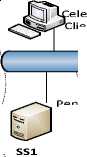
(a) Architecture
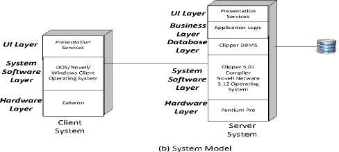
Fig.4. Architecture and System Model of the Central/Regional Office Deployment
-
A. Central/Regional Offices Deployment Scenario
The application has been studied and analyzed using the proposed approach of LSU in the context of Migration. First, the architecture model of the legacy system is taken and converted to a system model comprising of layers and artefacts as shown above in Fig. 4(a) and 4(b). The conversion from architecture to the system model is explained below:
-
1 The architecture of the case study system of central/regional office deployment is depicted in Fig. 4(a) above. The above scenario is a typical multi-system deployment case which comprises of Servers, Clients and network connectivity.
-
2 The architecture is a host-based processing of a Client-Server Model and the notations used for Servers and Clients are as mentioned below.
-
• SS1 represents the Pentium Pro Server
-
• SS2 represents the Backup Server
-
• CS1 represents the Celeron Client
-
• CS2 represents the Pentium IV Client and
-
• CS3 represent the Core i3 Client
-
3 SS1 Server houses the application pertaining to consumer billing and collection including the Source Code, executable Binaries, Clipper Database, Clipper Compiler, Novell Netware Operating System and its Networking Software.
-
• The clipper database is the native database of the Clipper Compiler Ver. 5.01, the language type being procedural.
-
• The operating system is Novell Netware 3.12 with character user interface (CUI).
-
• The Hardware Platform is x86 and Server HDD is the storage.
-
4 SS2 Server is a backup Server which has the backup of the SS1 Server’s Source Code and Database in addition to the Novell Netware Operating System and its Networking Software. From the above, the modules of the SS1 and SS2 are not equal and is represented by m (SS1) ≠ m(SS2) as mentioned in our model.
-
5 Even though the configuration is different for the clients CS1, CS2 and CS3 they act as a dumb
terminal which is a DOS and Novell client that has the requisite networking software. These Clients access the application residing in the Server in a Local Area Network and is represented as m(CS1) = m(CS2) =m(CS3).
-
6 The Server SS1 and CS1 are considered for the further process. CS2 has been left out due to the reason that they have the same functionality as CS1. The Server SS2 is not considered as the same is a backup server.
The Layers, Artefacts and mapping of the artefacts with the corresponding Layers of the case study system are as follows:
Layers
The layers required or the case study system based on the architecture and the study made in line with our proposed model are as mentioned below:
-
• Presentation Layer
-
• Business Logic Layer
-
• Data Access Layer
-
• System Software Layer
-
• Hardware Layer
Artefacts
The study made on the constituents of the Servers and Clients of the case study system had enabled us to find the relevant list of artefacts. The artefacts are listed below:
-
• User Interface
-
• Database
-
• Application Logic
-
• Operating System
-
• Network Software
-
• Compiler
-
• Server
-
• Client
-
• Network
-
• Hardware Platform
-
• Storage
The mapping of artefacts with the corresponding layers is shown in the following Table 11.
Table 11. Mapping Of Artefacts with Layers
|
Layers |
Artefacts |
|
Presentation Layer |
User Interface |
|
Business Logic Layer |
Application Logic |
|
Data Access Layer |
Database |
|
System Software |
Operating System, Compiler, Network Software |
|
Hardware Layer |
Server, Client, Hardware Platform, Storage |
The system model using the SS1 and CS1 has been derived based on the above steps and is represented in Fig. 4(b). As per our proposed model, the formal representations of the Layers, Artefacts and their mapping with the associated layers have been presented below:
Layers L = { “Presentation ”, ’’Business Logic”, "Data Access ”, “System Soft-ware”, "Hardware”}
" Source Code ", " UI
" "
database ", " App logic ", " System Software ", " OS ", " N / w Software ",
Artefacts A = <
" Compilers ", " DBMS Storage "," DBMS "," DBMS State "," DBMS Type ", " Hardware ", " Network ", " Compute ", " Server ", " Hardware Storage "
>
|
Layers/Artefacts |
UI |
Database |
App Logic |
OS |
N/w Software |
Compilers |
Network |
Server |
Hardware Storage |
|
|
Relationship |
Presentation |
1 |
0 |
0 |
0 |
0 |
0 |
0 |
0 |
0 |
|
Between |
Layer |
|||||||||
|
Layers and |
Business Logic |
0 |
0 |
1 |
0 |
0 |
0 |
0 |
0 |
0 |
|
Associated |
Layer |
|||||||||
|
Artefacts |
Data Access |
0 |
1 |
0 |
0 |
0 |
0 |
0 |
0 |
0 |
|
RLA = |
Layer |
|||||||||
|
(L,A) = |
System Software Layer |
0 |
0 |
0 |
1 |
1 |
1 |
0 |
0 |
0 |
|
Hardware Layer |
0 |
0 |
0 |
0 |
0 |
0 |
1 |
1 |
1 |
|
|
The matrix |
RLA has been |
used |
to represent the |
Server and |
Hardware |
Storage. |
The UI, |
database |
||
mapping of Layers L with the artefacts A. The system Software Layer has mapped its artefacts of Operating System, Networking Software and Compilers, whereas the Hardware has its artefacts mapped viz., Network,
and
Application Logic artefacts have been mapped to the corresponding layers of Presentation, database and application respectively. In the above matrix, the value represents its association with the Layers.
Source Code DBMS
Hardware Network Compute
H/w Platf orm Storage
System Software OS
N/wS/w ^Compilers
Relationship Among Artefacts RAA=(A,A) =
|
5 sc |
1 5 |
1 |
§ 1 s |
= a: |
|
|
0 |
/ |
0 |
0 |
0 |
|
|
0 |
i |
0 |
0 |
0 |
|
|
0 |
1 |
0 |
0 |
0 |
|
|
0 |
0 |
0 |
1 |
0 |
|
|
0 |
0 |
0 |
0 |
1 |
|
|
0 |
0 |
0 |
1 |
1 |
|
|
0 |
0 |
0 |
1 |
1 |
1 |
|
i |
1 |
i |
0 |
0 |
0 |
|
0 |
0 |
0 |
I |
1 |
i |
|
0 |
0 |
0 |
1 |
1 |
i |
|
0 |
0 |
0 |
0 |
I |
i |
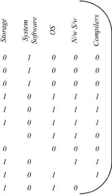
The relationship among the artefacts is represented by the above matrix RAA which is based on the Artefact Dependency Repository. The value of 1 represents the relationship between the corresponding artefacts in the row and its column whereas the value 0 indicates no relationship among the artefacts. The relationship is not applicable when the cell value is blank.
The above scenario is a typical multi-system deployment case which comprises of Servers, Clients and network connectivity as shown in Fig. 4.
The relationship among the multiple systems viz., Servers(SS1, SS2), Clients(CS1, CS2, CS3) and both Servers and Clients are represented by RS as shown below.
Relationship among Multiple System RS =

SS2
CS1
CS2

-
B. Collection Centre Deployment Scenario
The deployment scenario for Collection Centres is Single System Deployment, where the standalone systems are used for collection of payments from the citizen. The data required for the collections are brought on the offline media and uploaded in the standalone systems for their daily collections. There is no online updation of data, however, the updation is carried out at the end of the day on offline mode with the central/regional office server. The Collection Centres that have a standalone deployment type uses executable binaries of the collection module that generate receipts for the collection made and the data gets updated with the central server on offline mode on a daily basis at the end of the day. From the above case study, having two different types of deployment, it is evident that the LSU model and its formal mathematical model proposed is complete and is capable of representing any Legacy System in the context of LSU.
-
VIII. C onclusion
The LSU an important phase in the process of migration of legacy systems have been surveyed and discussed in detail along with the techniques and tools in use. The need for exploring the artefacts at the system level in addition to source code has been emphasised. The Artefact Repository has been built using the artefacts identified at the system level that are part and parcel of any legacy system. Further, they have been classified as implementation and documentation artefacts. The Artefact Dependency Repository has been enunciated through an exhaustive and explorative process and the dependencies among the artefacts have also been depicted. Formal representation of LSU using a formal language found lagging in the literature we have surveyed has been presented and demonstrated with the help of a case study. Migration impact analysis of artefacts consequence to LSU and Migration Analysis is our work in progress and future work.
References A formal model for legacy system understanding
- S. Comella-Dorda, K. Wallnau, R. C. Seacord, and J. Robert, “A survey of black-box modernization approaches for information systems,” in Proceedings of the International Conference on Software Maintenance (ICSM’00), 2000, p. 173.
- A. Sivagnana ganesan and T. Chithralekha, “A Survey on Survey of Migration of Legacy Systems,” in Proceedings of the International Conference on Informatics and Analytics,ACM, 2016, p. 72.
- B. Wu, D. Lawless, J. Bisbal, J. Grimson, V. Wade, D. O’Sullivan, and R. Richardson, “Legacy Systems Migration - A Method and its Tool-kit Framework,” in Proceedings of the APSEC’97/ICSC’97: Joint 1997 Asia Pacific Software Engineering Conference and International Computer Science Conference. Hong Kong, China, 1997, pp. 312–320.
- R. Khadka, A. Saeidi, A. Idu, J. Hage, and S. Jansen, “Legacy to SOA Evolution: A Systematic Literature Review,” A.D. Ionita, G. Lewis & M. Litoiu (Eds.) Migrating to SOA and Cloud Environments: Challenges in Service Oriented Architecture and Cloud Computing Environments: IGI Global, 2013. [Online]. Available:http://www.igi-global.com/chapter/lega cy-soa-evolution/72212.
- M. Srinivas, G. Ramakrishna, K. Rajasekhara Rao, and E. Suresh Babu, “Analysis of legacy system in software application development: A comparative survey,” Int. J. Electr. Comput. Eng., vol. 6, no. 1, pp. 292–297, 2016.
- R. Khadka, A. Saeidi, S. Jansen, and J. Hage, “A structured legacy to SOA migration process and its evaluation in practice,” c2013 IEEE 7th Int. Symp. Maint. Evol. Serv. Cloud-Based Syst. MESOCA 2013, vol. 4, no. March, pp. 2–11, 2013.
- S. Alahmari, D. De Roure, and E. Zaluska, “A Model-Driven Architecture approach to the efficient identification of services on Service-Oriented Enterprise Architecture,” in Proceedings - IEEE International Enterprise Distributed Object Computing Workshop, EDOC, 2010, pp. 165–172.
- R. Khadka, G. Reijnders, A. Saeidi, S. Jansen, and J. Hage, “A Method Engineering Based Legacy to SOA Migration Method,” in Proceedings of the 27th International Conference on Software Mainenance(ICSM), 2011, pp. 163–172.
- A. E. Roger, “Migration of Legacy Information System based on Business Process Theory,” Int. J. Comput. Appl., vol. 33, no. 2, pp. 27–34, 2011.
- S. P. Reiss, “Constraining software evolution,” in International Conference on Software Maintenance, 2002. Proceedings., 2002, pp. 162–171.
- J. Cha, C. Kim, and Y. Yang, “Architecture Based Software Reengineering Approach for Transforming from Legacy System to Component,” pp. 266–278, 2004.
- J. Lavery, C. Boldyreff, B. Ling, and C. Allison, “Modelling the evolution of legacy systems to Web-based systems,” J. Softw. Maint. Evol. Res. Pract., vol. 16, no. 1–2, pp. 5–30, 2004.
- A. Erradi, S. Anand, and N. Kulkarni, “Evaluation of Strategies for Integrating Legacy Applications as Services in a Service Oriented Architecture,” in Proceedings of the IEEE International Conference on Services Computing SCC06, 2006, pp. 257–260.
- Y. Pena, D. Correal, and T. Hernandez, Reusing legacy systems in a service-oriented architecture: A model-based analysis, vol. 6413 LNCS. 2010.
- M. Sneed, “Planning the Reengineering of Legacy Systems,” IEEE Softw., vol. 12, no. 1, pp. 24–34, 1995.
- F. Arcelli, C. Tosi, and M. Zanoni, “Can design pattern detection be useful for legacy system migration towards SOA?,” Proc. 2nd Int. Work. Syst. Dev. SOA Environ. SDSOA ’08,Germany, pp. 63–68, 2008.
- D. Binkley, “Source Code Analysis : A Road Map Source Code Analysis : A Road Map,” in Proceedings of the Future of Software Engineering FOSE ’07, 2007, pp. 104–119.
- M. Razavian and P. Lago, “A systematic literature review on SOA migration,” Jourrnal SoftwareEvolution Process, vol. 27, no. May, pp. 337–372, 2015.
- E. Stroulia, P. Iglinski, and P. Sorenson, “User Interface Reverse Engineering in Support of Interface Migration to the Web,” World Wide Web Internet Web Inf. Syst., pp. 271–301, 2003.
- S. R. Tilley, S. Paul, and D. B. Smith, “Towards a framework for program understanding,” in WPC ’96. 4th Workshop on Program Comprehension, 1996, pp. 19–28.
- A. A. Belevantsev, E. A. Veselevich, and V. P. Ivannikov, “Analysis of Entities in C and C ++ Programs and Relations between Them for Program Understanding,” Program. Comput. Softw., vol. 42, no. 1, pp. 49–53, 2016.
- P. Bhallamudi and S. Tilley, “SOA migration case studies and lessons learned,” in 2011 IEEE International Systems Conference, 2011, pp. 123–128.
- F. Cuadrado, B. García, J. C. Dueñas, and H. A. Parada, “A Case Study on Software Evolution towards Service-Oriented Architecture,” in 22nd International Conference on Advanced Information Networking and Applications -Workshops,Okinawa, Japan, 2008, pp. 1399–1404.
- S. Li and L. Tahvildari, “E-BUS : A Toolkit for Extracting Business Services from Java Software Systems,” in Proceedings of Companion of the 30th international conference on Software engineering ICSE Companion ’08, Leipzig,Germany, 2008, pp. 961–962.
- Z. Zhang, R. Liu, and H. Yang, “Service Identification and Packaging in Service Oriented Reengineering,” in Proceedings of the 17th International Conference on Software Engineering and Knowledge Engineering, 2005.
- G. Mazlami, J. Cito, and P. Leitner, “Extraction of Microservices from Monolithic Software Architectures,” in 2017 IEEE International Conference on Web Services (ICWS), 2017.
- A. Ahmad and M. A. Babar, “A framework for architecture-driven migration of legacy systems to cloud-enabled software,” in Proceedings of the First International Conference on Dependable and Secure Cloud Computing Architecture - DASCCA ’14, 2014, pp. 1–8.
- R. Heckel, R. Correia, C. Matos, M. El-Ramly, G. Koutsoukos, and L. Andrade, “Architectural transformations: From legacy to three-tier and services,” in Software Evolution, 2008, pp. 139–170.
- S. Tilley, “A Reverse- Engineering Environment Framework,” 1998. [Online]. Available: http://resources.sei.cmu.edu/library/asset-view.cfm?AssetID=13047. [Accessed: 15-Jun-2017].
- S. Li, F. Chen, Z. Liang, and H. Yang, “Using Feature-Oriented Analysis to Recover Legacy Software Design for Software Evolution .,” in Proceedings of the 17th International Conference on Software Engineering and Knowledge Engineering (SEKE’2005), Taipei, Taiwan, Republic of China, 2005, pp. 336–341.
- G. Canfora, A. R. Fasolino, G. Frattolillo, and P. Tramontana, “A wrapping approach for migrating legacy system interactive functionalities to Service Oriented Architectures,” J. Syst. Softw., vol. 81, no. 4, pp. 463–480, 2008.
- P. Dugerdil and D. Sennhauser, “Applying financial time series analysis to the dynamic analysis of software,” in proceedings of the 4th International Conference on Software and Data Technologies, Sofia, Bulgaria, 2002, pp. 194–201.
- H. Y. Huang, H. F. Tan, J. Zhu, and W. Zhao, A lightweight approach to partially reuse existing component-based system in service-oriented environment, vol. 5030 LNCS. Springer, Berlin, Heidelberg, 2008.
- Z. Zhang, D. D. Zhou, H. J. Yang, and S. C. Zhong, “A service composition approach based on sequence mining for migrating e-learning legacy system to SOA,” Int. J. Autom. Comput., vol. 7, no. 4, pp. 584–595, 2010.
- C. Zillmann, A. Winter, A. Herget, W. Teppe, M. Theurer, A. Fuhr, T. Horn, V. Riediger, U. Erdmenger, U. Kaiser, D. Uhlig, and Y. Zimmermann, “The SOAMIG Process Model in Industrial Applications,” in 15th European Conference on Software Maintenance and Reengineering (CSMR), 2011, pp. 339–342.
- H. M. Sneed and S. H. Sneed, “Creating Web services from legacy host programs,” in Proceedings - 5th IEEE International Workshop on Web Site Evolution: Architecture, Gernmany, 2003, pp. 59–65.
- J. Van Geet and S. Demeyer, “Lightweight Visualisations of COBOL Code for Supporting Migration to SOA Lightweight Visualisations of COBOL Code for Supporting Migrating to SOA,” vol. 8, 2008.
- P. C. C. Linda M. Northrop and L. O. with Felix Bachmann, John Bergey, Gary Chastek, Sholom Cohen, Patrick Donohoe, Lawrence Jones, Robert Krut, Reed Little, John McGregor, “A Framework for Software Product Line Practice, Version 5,” 2012. [Online].Available: http://www.sei.cmu.edu/productlines/frame_report/config.man.htm. [Accessed: 20-Jul-2017].
