A Review: DWT-DCT Technique and Arithmetic-Huffman Coding based Image Compression

Автор: Gaurav Kumar, Er. Sukhreet Singh Brar, Rajeev Kumar, Ashok Kumar
Журнал: International Journal of Engineering and Manufacturing(IJEM) @ijem
Статья в выпуске: 3 vol.5, 2015 года.
Бесплатный доступ
Nowadays, the volume of the data is increasing with time which generates a problem in storage and transfer. To overcome this problem, the data compression is the only solution. Data compression is the science (or an art) of representing information in compact form. This is an active research area. Compression is to save the hardware storage space and transmission bandwidth by reducing the redundant bits. Basically, lossless & lossy are two types of data compression technique. In lossless data compression, original data is similar to decompressed or decoded data, but in lossy technique is not same. In this paper, Study lossless image compression technique. The purpose of image compression is to maximum bandwidth utilization and reduces storage capacity. This technique is beneficial to image storage and transfer. At the present time, Mostly image compression research have focused on the wavelet transform due to better performance over another transform. The performance is evaluated by using MSE & PSNR. DWT, quantization, Arithmetic, Huffman coding and DCT techniques are briefly introduced. After decompression, the quality of image is evaluated using PSNR parameter between original & decoded image. Compression ratio (CR) parameter is calculated to measure how many times image compressed.
DWT, DCT, Quantization, Arithmetic Coding, Huffman Coding, PSNR, CR
Короткий адрес: https://sciup.org/15014385
IDR: 15014385
Текст научной статьи A Review: DWT-DCT Technique and Arithmetic-Huffman Coding based Image Compression
Published Online September 2015 in MECS
Available online at
At the same time it should be considered that, the image compression technique must be able to reconstruct the image with low loss or without loss as compared to original image. Nowadays, image compression is very important to solve the problems of storage capacity and maximum bandwidth utilization. When internet started, then the need of image compression arised, so as “the need is a mother of an invention” .The task is compressing the image begun. On ground level, when image compression is performed, then an input image is analyzed and undetectable to the viewer is neglected . The objective of the image compression is to reduce the redundancy in the image and to store and transmit data in efficient form [1]. Lossless and lossy are types of image compression technique. Lossless image compression is minimized the size of image, without loss of data or information after decompressing. It is known as zero loss information. The original image is similar to the decompressed image, but CR is low. Decoded image is exactly same as original image. Decoded image is known as decompressed image. Original image is known as uncompressed image. Lossy image compression is minimized the size of image, with loss of data or information after decompressing. The original image is not similar to the decompressed image, but CR is high. Decoded image is closer to original image [2]. There are various methods for image compression, but most useful techniques are following: Discrete Wavelet Transform (DWT), Vector Quantization (VQ) and Discrete Cosine Transform (DCT). These techniques are lossless except VQ. VQ is lossy technique. In the image processing, the most of the works have been done on the grayscale image. This grayscale image is of 8 bits. In this paper, Lena & Baboon two input color images are taken. The color image is a combination of Red, Green, and Blue. So, the color image is 24 bits. Conclude that, the total number of possible color is 224 . But all the color combination is not perceived by the human eye. That means the human vision is not differentiated so many colors. Firstly, RGB is extracted from a color image. Then each part is compressed separately. Finally, all parts are combined. All simulation works have been done on MATALB [3].
The Transform technique can be classified into various categories which are as discussed below:
Spatial and transform are mainly two working domain in image processing. In spatial domain, we directly deals with the pixel, but in transform domain deals with frequency. There are many transforms like DWT (Discrete Wavelet Transform), DCT (Discrete Cosine Transform), DFT (Discrete Fourier Transform) and FFT (Fast Fourier Transform). In these transform technique, DWT is better than other transform, because DWT captures the frequency, its location and multi resolution property [4]. Wavelet domain is a comparatively new and promising transform domain for compression. When DWT is applied to an image then the image is separated into four different components: to the human perception, digital watermarking is classified in two parts:
-
i. Approximation image component (LL)
-
ii. Horizontal detail component (HL)
-
iii. Vertical detail component (LH)
-
iv. Diagonal detail component (HH)
This image process of decomposition can be repeated to compute multi-level decomposition. These Fig.1 shown the three-level wavelet decomposition.
|
LL3 |
HL3 |
HL2 |
HL1 |
|
LH3 |
HH3 |
||
|
LH2 |
HH2 |
||
|
LH1 |
HH1 |
||
Fig. 1. Three Level DWT Decomposition of an Image
By use of the advantages of DWT, model of HVS is more accurate to FFT and DCT [5]. In general, most of the signal energy is concentrated in the Approximation sub-band. So, Image compression provides higher CR but degrade the quality of the image. The LH, HL, and HH sub bands are included the edges and textures of the image and get higher imperceptibility, but at the expense of the CR. So, using these facts, easily select the subband for the compressing [6].
Advantages of DWT over Discrete Fourier Transform are as given below:
-
i. Its ability to generate temporal resolution.
-
ii. It captures both frequency and location information.
Mathematical expression for Discrete Wavelet Transform
Approximation coefficient: LL sub-band is known as Approximation coefficient. Original signal is two times passes through low pass filter and down sampling by 4.
W
Detail coefficient: It is combination of HL, LH and HH sub-bands. Original signal is two times passes through combination of low-high pass filter and down sampling by 4.
^O-,k)=^Z„s(n)^ j,k (n)
Where, j >j_0 and s(n), p/o ,k (n)and ^ j,k (n) are functions of discrete variables n= 0, 1, 2,........,M-1.
Mathematical expression for Inverse Discrete Wavelet Transform
sto = ^w^Uo^jk^+l^^
Normally, Let jQ=0 and select M to be a power of 2 (M= 2 j), so that the summations are performed over j =
0, 1 ... j -1 and k= 0, 1, 2...............2j-1.
-
2.2. Discrete Cosine Transform
The two main reasons that why DCT is better than DFT are as given below:
-
i. The DFT can’t concentrate the energy of transform at a low level, but DCT can concentrate. According to parse- Wal's theorem, energy is same in the frequency domain as well as a spatial domain. Human eyes are sensible for low frequency, so we can concentrate on low-frequency component and reduce the participation of high-frequency component after taking DCT transform.
-
ii. In image compression, blocking the effect of DCT is less than DFT.
2D-DCT can be defined as follows:
D(i,j)=√=C(i)C(j)∑x=o ∑Y=0Р(Х, Ү) соs. ( ) m /соs. ( "" ) /) (4)
Where, P(x, y) is an input matrix image NxN, (x, y) are the coordinate of matrix elements and (i, j) are the coordinate of coefficients, and
C(U) ={√ 5 if U=0} (5)
1 if U>0
Here, the value of c (u) has only two for input u=0, or u>0.
-
2D-I DCT can be defined as follows:
P(Х, Ү) = h ∑i^Q1 ∑ r.-o1С(i)C(j)D(i, j) соs. ( ™ ) ™ /соs. ( 2™ ) /
Table 1. Comparison of DWT and DCT technique [7]
|
Sr. No. |
Parameter |
DCT |
DWT |
|
1. |
Compression ratio |
Low |
High |
|
2. |
PSNR |
Low |
High |
|
3. |
MSE |
High |
Low |
|
4. |
BER |
High |
Low |
|
5. |
Encoding Time |
High |
Low |
Flowchart of DCT:

RGB Image (Input Image)

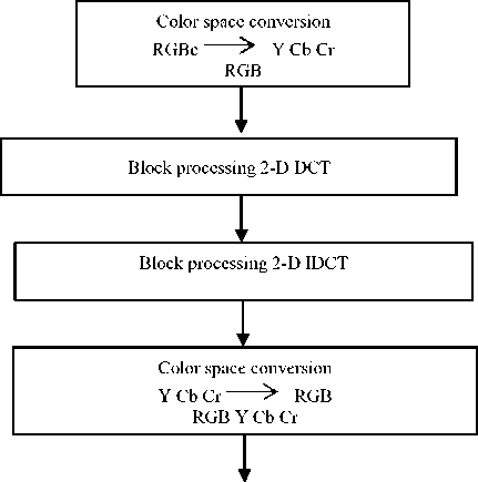
Reconstructed Image


Fig. 2. Flowchart of DCT
-
3. Variable Length Coding
-
3.1. Arithmetic Coding
-
Arithmetic coding is lossless coding. It is also known as variable length encoding technique. It is based on probability value. A sequence of input symbols is represented by an interval of real numbers between 0.0 and 1.0. The decision and context are generated by context formation and encoded in the arithmetic encoder. The basis of the binary arithmetic encoder is recursively probability distribution. Since in binary arithmetic encoder, there are two sub-intervals. With each step of decision, the present probability interval is subdivided into two sub-intervals. If value of probability or decision is 1 then a more possible symbol (MPS), otherwise less possible symbol (LPS).The probability of More Possible Symbol and less possible symbol are represented in a gray interval as well as a white interval. The basic function of the arithmetic encoder is to returning the value of MPS and LPS according to the context and decision from context formation. The intervals of MPS and LPS are dynamically changed. If context and decision are equal to the value of MPS, then code of MPS, otherwise code LPS [8]. The probability distribution is shown in Fig.3.
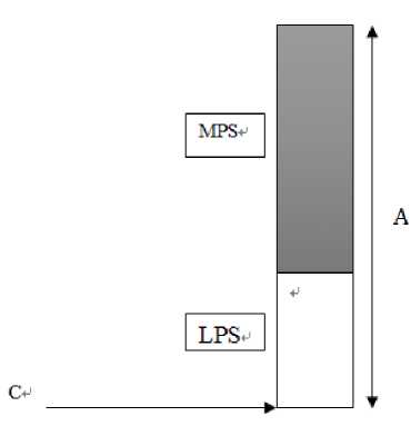
Fig. 3. Arithmetic Coding of Probability Distribution
Limitations of Arithmetic Coding:
-
i. It is not a unique binary code because any encoded value within final range can be considered as the encoded message.
-
ii. The encoding and decoding algorithm do not transmit anything until the completion of the process. This limitation can be reduced by the use of the binary arithmetic coding.
-
iii. The precision requirement grows with the length of the message.
-
iv. To finding the range of encoding and decoding process, multiplication is used. Multiplication process is complex for range finding.
-
3.2. Huffman Coding
Huffman coding is lossless encoding technique. This coding is known as entropy encoding algorithm. This algorithm is use variable- length code table for source symbol. Variable-length code table is derived basis on estimated probability occurrence of the source symbol. The coding is specific choosing of the source symbol. The term prefix code of meaning is the bit string representing a unique symbol is never prefixed of any other symbol. Prefix code expressed the most common source symbols using shorter strings of bits used for less common source symbols. Huffman was designed most efficient compression method. The mapping of individual source symbols to unique strings of bits will produce the smaller size of the output. For Huffman code, in the linear time input probability is sorted. When uniform probability distribution and number of members which is a power of two then Huffman is equivalent to binary block encoding. This coding is a widespread method for creating prefix codes [9].
Algorithm for Huffman coding:
Data structure used: Priority queue = Q, A is given alphabet
Huffman (c)
{ n = |c|
Q = c
For i = 1 to n-1
{ do Z = Allocate-Node ()
x = left[z] = EXTRACT_MIN (Q)
y = right[z] = EXTRACT_MIN (Q)
F[z] = F[x] + F[y]
INSERT (Q, z)
} return EXTRACT_MIN (Q)
}
Complexity is O (n log n), each priority queue of complexity is O (log n). Limitations of Huffman Coding:
-
i. This code gives an optimal solution when only if the exact probability distribution of the source symbols is known.
-
ii. The encoding of each symbol is with an integer number of bits.
-
iii. When changing the source statistics then Huffman coding is not efficient.
-
iv. Due to the large length of the least probable symbol of this code. So, storage in a single word or basic storage is complex.
-
4. Quantization
|
Sr. No. |
Parameter |
Arithmetic coding |
Huffman coding |
|
1 |
CR |
Very good |
Poor |
|
2 |
Compression Speed |
Slow |
Fast |
|
3 |
Decompression Speed |
Slow |
Fast |
|
4 |
Memory Space |
Very low |
Low |
To digitization of image, sampling and quantization are necessary process because image is combination of coordinate and amplitude. Digitizing the coordinate values is called sampling. Digitizing the amplitude value is called quantization. Sampling and quantization is similar process. In quantization process, the sampled signal is to assign a discrete value. The input signal is continuous, but output signal is discrete. This method is works like analog to digital converter. Quantization process of mapping a large set of input values into a smaller set, such as rounding values to some unit of precision [11].
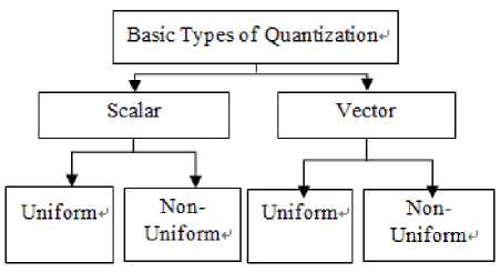
Fig. 4. Types of Quantization
If coefficient value is greater the threshold value then coefficient replaced by one, otherwise replaced by zero. The main steps of quantization are given below:
-
i.
-
ii.
-
iii.
iv.
To find the threshold value.
Condition (if, else) is applied with the threshold value.
This condition is returned the binary value.
Quantized matrix is in form of binary value.
Flowchart of quantization:
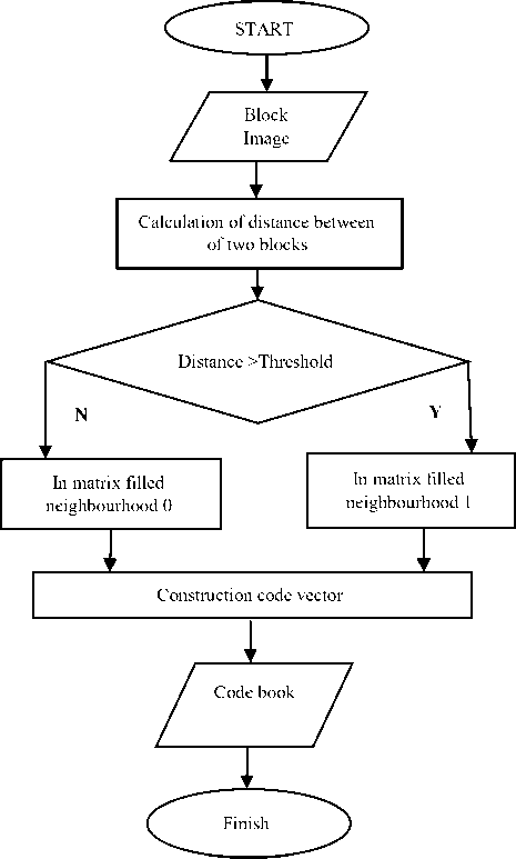
Fig. 5. Flowchart of Quantization
-
4.1. Scalar quantization
-
4.2. Vector quantization
-
5. Performance Matrices
In uniform quantization, each sample’s size is equal but in non-uniform each sample’s size is not equal. It is a lossy technique. In this method, Each sample is quantized independently. A scalar quantizer is defined in equation(1). Where Q(.) is a function of the role, mapping of continuous-valued variables. P(s) is a probability density function. A discrete set of reconstruction levels are r i ( i=1, 2…L). The set of the decision levels are d i (i=1, 2….L); this is applied to the continuous-valued samples s, such that
Q(s) = ri if s ∈ (ԁi-1 -ԁi)
Where, i = 1, 2 ...L
L is output level. The range of sample value is between (d i-1 - d i ). Finally, we can say that quantizer is the reconstruction level.
For a good quality image after decompression, following conditions must hold:
-
• PSNR should be high
-
• MSE should be low
-
• Compression ratio should be high
Compression ratio (CR): CR is a parameter by which measure the how many times image compressed.
CR formula is as:
CR=
Size of original image
Size of Compressed image
When size of compressed image is reduced then CR is high. Because relation between CR and compressed image is inversely proportional.
Quality Evaluation: Quality is evaluated by using PSNR (peak signal-to-noise ratio) value. PSNR is measured between two images. Here, PSNR is measured between original image and decompressed image.
PSNR formula is as:
Where MAXi2 is maximum pixel intensity value
MSE: MSE is the Mean square error among original and decompressed image. MSE formula is as:
MSE = ∑ i^Q1 ∑ j=l [{x(i, j) - у(i, j)} 2]
-
6. Literature Review
Proposed a vector quantization algorithm.There are three phases of this proposed algorithm. These phases are initialization, iterative and finalization. First phase initialization is based on Min-Max algorithm. Second phase iterative phase is based on adaptive LBG algorithm. Third finalization is frees the codebook from redundancy. The performance and the compression ratio of the proposed algorithm will be much better with images that do not have much of details such as the standard images. The medical applications require saving a huge amount of data [11].
Says that, the coding techniques use correlation and de-correlation approach for color image compression. The de-correlated space transformed the color image into YUV or YCbCr. The all de-correlated color components are encoded separately. In this paper, there are two standards are used. These two image compression standards are JPEG and JPEG2000. CBA is a different method. All the parameters of the approximation function and part of the approximation errors are encoded. For the purpose of enhancing of algorithm’s performance, DCT block transform technique is used. Comparison of two versions of new algorithms, Laplacian probability model for the DCT coefficients and down-sampling the subordinate colors have done. Simulation results are shown that the new CBA algorithms. This algorithm is superior to presently available algorithms based on the common de-correlation approach, such as JPEG [13].
A proposed a novel bit-rate-reduced approach for reducing the memory required to store a remote diagnosis and rapidly transmission. In this paper, an 8×8 Discrete Cosine Transform approach is adopted to perform the sub-band decomposition. Improved SPIHT is works like an entropy coding. The data is organized by Improved SPIHT. A DCT spectrum is obtained by transformation. By use of the wavelet-based algorithm, the single frequency domain is converted into the various frequency domain.The detailed information is store by translation function. Proposed method gives better CR than individual SPIHT or DCT [14].
Proposed that lossless and mutable steganography scheme for hiding stealthy data. This data is present in each block of quantized DCT coefficients in JPEG images. The two consecutive zero coefficients of the medium-frequency constituents in each block are used to hide the stealthy data. Moreover, the scheme modifies the quantization table to maintain the feature of the stego-image. Tentative results also confirm that the proposed scheme can provide estimated acceptable image quality of stego-images and fruitfully achieve reversibility [15].
A proposed new technique CWT (Continues Wavelet Transform). This technique is compare two famous technique. The first technique is DWT. The second technique is DCT. The output of MLP (Meridian Lossless Packing) and SVM (Support Vector Machine) are in the form of training/testing performance. The generalization ability and training time are compared. Comparison of MLP and SVM based on the results reported in tables shows that SVM classifier with (K–A) training algorithm has improved Tr.P at least four times. Implementation of the selected and proposed classification structures show [15].
Proposed a hybrid schemes for effective image compression which has gained enormous popularity among researchers. To gain high compression rates a combination of DWT and DCT used as a hybrid compression technique at different threshold value on DWT decomposed sub-bands. While DCT transform is applied on HL and LH sub-bands with maintained the quality of the decompressed medical image. The sub-bands are the quantized basis on threshold values. Finally, the entropy coding is applied to quantized subband. The coding performance is included compression rate, compression ratio and image quality. Simulation results showed that the coding performance can be significantly improved by the hybrid DWT-DCT algorithm [17].
Proposed improved hybrid technique. Hybrid technique is combination of DWT and DCT. Comparative results for DCT, DWT and hybrid DWT-DCT compression techniques are given. Quality is measured by using PSNR. DWT two threshold method gives better quality compare to DCT and one threshold DWT. DWT two threshold is also known as “improve DWT”. Finally, according to this paper, the improved-DWT-DCT compression technique of result is better than DCT based JPEG in terms of PSNR [18].
Said that image compression is very important technique now a day for storing and transmission of digital data. This paper suggests a proposal of new compression technique. DWT is the basis of this new proposed compression technique. The proposed technique is firstly DWT apply on the image after that thresholding applies on sub-bands. If sub-bands of coefficient less than the threshold value then assign zero value to subband coefficient, otherwise encoding algorithm apply on sub-bands. The accuracy of the algorithm has been justified over images. This algorithm of efficiency is compared with other common compression standards. The simulation results of this proposed technique provides sufficient high compression ratios compared to other compression techniques [19].
Used to various transformation techniques for data compression. In this paper, proposed a hybrid DWT-DCT is used with the advantages of Huffman algorithm. Huffman coding is used to encode the compressed bit streams at the compression stage. In reconstruction stage, it is used to decode the received encoded bit streams. This proposed method have given high compression ratio [21].
Deals with data rate and storage capacity. By compressing the data, these requirements are achieved. There are a lot of image compression techniques, but this paper concentrates on Set Partitioning in Hierarchical Trees, which is a wavelet-based compression algorithm that offers good compression ratios, fully progressive bitstream and good image quality. According to this paper, Arithmetic with SPIHT compression technique gives better data rate and image quality. The size of the images is reduced after compression [22].
Describes the difference between the aim of image compression and steganography. In this paper, the improvement of image compression is done through steganography. The definition of both techniques is not clear. In this study, the data compression technique is implemented as twice time. First, taken advantage of energy compaction using JPEG to reduce redundant data. Second, embed some bit blocks within its subsequent blocks of the same image with steganography. The embedded bits are not only increase the file size of the compressed image, but also decrease the file size. Illustrated, how these techniques can be used jointly to compress and to hide data within the same image. The idea behind this work is to compress the target block of an image using JPEG extension, and then hide the resulting bits into subsequent blocks of the compressed image. Simulation results showed that this method gives better compression rates as well as high quality [23].
Says that, Image Compression is a demanding field in this era of communication. There is a time to study and analyze the literature for image compression, as the demand for images and computer animation has needed high data rate. Multimedia data whether graphics, audio, video data which is uncompressed requires minimum transmission bandwidth and storage capacity. So, Image compression technique needs to all multimedia applications to save storage and transmission time. In this study, Discussed different compression algorithms are used to reduce the size of images without quality reduction [24].
Proposed a genetic algorithm (GA) based on discrete wavelet transformation (DWT) to reduce disadvantages of the fractal encoder. The fractal encoder technique is more time-consuming. In this paper, two fractal encode algorithms have been proposed to overcome the problem of the time-consuming drawback for the fractal encoder. First, a FIC (Fractal Image compression) using DWT is proposed to ignore unnecessary MSE computations produced by Dihedral transformations. The proposed Generic algorithm is 100 times faster than the full search method with the penalty of 1.13 dB decay at the retrieved image quality [25].
Presented simple color space transformations for lossless image compression. Image Compression is Using Discrete Wavelet Transform. Starosolski have proposed RDgDb and LDgEb simple color space transformations for lossless image compression and a couple of their variants. These three techniques are compared. The three sets of test images and significantly different compression algorithms are: predictive JPEG-LS, Discrete Wavelet Transformation-based JPEG2000 and Discrete Cosine Transformation-based JPEG X. The overall best lossless ratios were obtained using the JPEG-LS algorithm and the modular and 2 symmetrical modulo operations [27].
Critical analysis of Review of Literature:
In [20] this paper, Image is decomposed into four sub-bands using first level decomposition DWT after that LL1 band is further decomposed into four sub-bands using DWT. Then LL2 is operated with 2D-DCT after that DCT coefficients are encoded with Huffman coding. This hybrid technique shows good PSNR and CR.
After the review of the literature, it is found that many researchers have focus on compression, decompression and image quality estimation. Different types of hybrid techniques are studied. These hybrid techniques are DWT-DCT, DWT-SPIHT and DCT-SPIHT. Some of them emphasized on compression speed as well as decompression speed by using Hybrid Technique. Some researchers have discussed the fractal compression technique. This paper is based on advantages of DWT-DCT hybrid technique. This hybrid technique is used with Arithmetic and Huffman coding.
-
7. Conclusions
In this paper, Transform (DWT-DCT) and Variable length (Arithmetic-Huffman) coding have discussed briefly. Comparison of DWT-DCT have given in Table 1. DWT is better than DCT technique in terms of CR and PSNR values. But, In DCT technique have no blocking effect. Comparison of Arithmetic and Huffman have given in Table 2. Arithmetic coding of CR is higher than Huffman coding. Huffman coding takes less memory space compare to Arithmetic coding. Compression and decompression time of Huffman coding is less than the Arithmetic coding.
Список литературы A Review: DWT-DCT Technique and Arithmetic-Huffman Coding based Image Compression
- Gonzalez, R. C., & Woods, R. E. (2002). Digital Image Processing. New Jersey: Pearson Prentice Hall.
- Sayood, K. (2006). Introduction to Data Compression. San Francisco: Morgan Kaufmann. Roy, V. (2013).
- Mahfouz, A. A., & Salem, F. A. (2013). Performance Analysis, Controller Selection And Verification Of Electric Motor For Mechatronics Motion Control Applications, Using New MATLAB Built-In Function And Simulink Model. International Journal of Engineering and Manufacturing (IJEM), 3(2), 11.
- Spatial and Transform Domain Filtering Method for Image De-noising: A Review. International Journal of Modern Education and Computer Science (IJMECS), 5(7), 41.
- Dorairangaswamy, M. A & Padhmavathi, B. (2009). An effective blind watermarking scheme for protecting rightful ownership of digital images. In TENCON 2009 IEEE Region 10 Conference,1-6.
- Corinthios, Benchikh, S & Michael. (2011). A Hybrid Image Compression Technique Based On DWT and DCT Transforms, 1049-1065. Canada: IEEE.
- Gupta, M & Garg, A. K. (2012). Analysis of image compression algorithm using DCT. International Journal of Engineering Research and Applications (IJERA), 2(1): 515-521.
- Marpe, D., Schwarz, H & Wiegand, T. (2003). Context-based adaptive binary arithmetic coding in the H. 264/AVC video compression standard. Circuits and Systems for Video Technology, IEEE Transactions on, 13(7): 620-636.
- Venkatasekhar, D., & Aruna, P. (2013). A Fast Fractal Image Compression Using Huffman Coding. Asian Journal of Computer Science & Information Technology, 2(9): 272 – 275.
- Maan, A. J.(2013). Analysis and Comparison of Algorithms for Lossless Data Compression. International Journal of Information and Computation Technology, ISSN, 0974-2239, 3:139-146.
- Abouali, A. H. (2015). Object-based VQ for image compression. Ain Shams Engineering Journal, 6: 211-216.
- Howard, P. G & Vitter, J. S. (1996). Parallel lossless image compression using Huffman and arithmetic coding. Information processing letters, 59(2): 65-73.
- Gershikov, E., Lavi-Burlak, E & Porat, M. (2007). Correlation-based approach to color image compression. Signal Processing: Image Communication, 22(9): 719-733.
- Chen, Y. Y. (2007). Medical image compression using DCT-based subband decomposition and modified SPIHT data organization. International journal of medical informatics, 76(10): 717-725.
- Chang, C. C., Lin, C. C., Tseng, C. S & Tai, W. L. (2007). Reversible hiding in DCT-based compressed images. Information Sciences, 177(13): 2768-2786.
- Khorrami, H & Moavenian, M. (2010). A comparative study of DWT, CWT and DCT transformations in ECG arrhythmias classification. Expert systems with Applications, 37(8): 5751-5757.
- Mohammed, A. A & Hussein, J. A. (2010, December). Hybrid transform coding scheme for medical image application. 2010 IEEE International Symposium on Signal Processing and Information Technology (ISSPIT), 237-240.
- Corinthios, Benchikh, S & Michael. (2011). A Hybrid Image Compression Technique Based On DWT and DCT Transforms, 1049-1065. Canada: IEEE.
- Chowdhury, M. M. H & Khatun, A. (2012). Image Compression Using Discrete Wavelet Transform. IJCSI International Journal of Computer Science Issues, 9(4): 327-330.
- Bindu, K., Ganpati, A & Sharma, A. K. (2012). A Ccomparative Study of Image Compression Algorithm. International Journal of Research in Computer Science, 2(5): 37-42.
- Bharath, K. N., Padmajadevi, G. & Kiran. (2013). Hybrid Compression Using DWT-DCT and Huffman Encoding Techniques for Biomedical image and video application. International Journal of Computer Science and Mobile Computing, 2(5): 255-261.
- Hazarathaiah, A., Rao, P & Madhu, C. (2013). Medical Image Compression Using SPIHT Combined With Arithmetic. International Journal of Electronics and Communication Engineering, 2(5): 1-6.
- Jafari, R., Ziou, D & Rashidi, M. M. (2013). Increasing image compression rate using steganography. Expert Systems with Applications, 40(17): 6918-6927.
- Rehman, M., Sharif, M & Raza, M. (2014). Image compression: A survey. Research Journal of Applied Sciences, Engineering and Technology, 7(4): 656-672.
- Wu, M. S. (2014). Genetic algorithm based on discrete wavelet transformation for fractal image compression. Journal of Visual Communication and Image Representation, 25(8): 1835-1841.
- Vijayabhaskar, P. V. M & Raajan, N. R. (2013). Comparison of wavelet filters in image coding using hybrid compression technique. 2013 International Conference on Emerging Trends in VLSI, Embedded System, Nano Electronics and Telecommunication System (ICEVENT), 1-5.
- Starosolski, R. (2014). New simple and efficient color space transformations for lossless image compression. Journal of Visual Communication and Image Representation, 25(5): 1056-1063.
