Analysis of the impact of subgrade reinforcement technologies on the stability of structures designed on high-temperature permafrost soils

Author: Shepitko T.V., Artyushenko I.A., Akulich V.Yu., Polyansky A.V., Nozdrachev A.S.
Journal: Nanotechnologies in Construction: A Scientific Internet-Journal @nanobuild-en
Section: System solutions for technological problems
Article in issue: 4 Vol.17, 2025.
Free access
Introduction. Ensuring the stability of the subgrade in areas with permafrost soils is one of the most pressing challenges in modern design, construction, and operation of transportation infrastructure. In the context of global climate change and increasing anthropogenic loads on soil foundations, the search for effective ground reinforcement technologies has become a key area of research. This article presents an analysis of the impact of reinforcement technologies for high-temperature permafrost soils on the stability of structures. Methods and Materials. Two structural and technological solutions for reinforcing the foundation soils of the subgrade are considered: the use of jet grouting technology and the installation of vertical crushed stone columns. The study is based on numerical modeling of the stress-strain state of the subgrade on permafrost soils, both with and without the proposed structural and technological solutions. Results and Discussion. A comparative analysis of vertical displacements, shear deformations, and slope stability factors was performed for each technology. Overall, the proposed foundation soil reinforcement technologies improve the reliability of structures built on them, particularly the subgrade. The choice of foundation soil reinforcement technology should be based on an analysis of specific construction and operational conditions of the object – natural, technical, technological, and economic factors. Conclusion. It can be noted that in similar engineering-geological conditions, as described in this study, jet grouting is suitable for reinforcing foundation soils in areas with high stability and bearing capacity requirements, but with mandatory preliminary selection of the cement slurry and analysis of its exothermic behavior during strength gain. Vertical crushed stone columns, as a method of soil reinforcement, represent a promising structural and technological solution, especially for less heavily loaded sections.
Permafrost soils, subgrade, jet grouting, vertical crushed stone columns, numerical modeling
Short address: https://sciup.org/142245495
IDR: 142245495 | DOI: 10.15828/2075-8545-2025-17-4-415-426
Text of the scientific article Analysis of the impact of subgrade reinforcement technologies on the stability of structures designed on high-temperature permafrost soils
Original article
Шепитько Т.В., Артюшенко И.А., Акулич В.Ю., Полянский А.В., Ноздрачёв А.С. Анализ влияния технологий усиления основания земляного полотна на устойчивость сооружения, проектируемого на высокотемпературных многолетнемерзлых грунтах. Нанотехнологии в строительстве. 2025;17(4):415–426. – EDN: CCATHQ.
Ensuring the stability of the subgrade in areas with permafrost soils (PFS) is one of the most pressing challenges in modern design, construction, and operation of transportation infrastructure. This is because permafrost soils are highly sensitive to changes in temperature regimes.
In the context of global climate change and increasing anthropogenic loads on soil foundations, the search for effective ground reinforcement technologies has become a key area of research.
One of the promising methods for ground reinforcement is jet grouting technology, which enables the creation of strong soil-cement elements directly within
SYSTEM SOLUTIONS FOR TECHNOLOGICAL PROBLEMS the soil mass [1]. However, its application in permafrost regions requires special attention, as the process of injecting cement slurry under high pressure generates heat [2–4], potentially causing localized thawing of the soils and reducing their bearing capacity [5–8]. An alternative solution involves vertical columns made of crushed stone, which provide a drainage effect and improve the mechanical properties of the soils but are limited by their strength characteristics and range of application [9–12].
In Russia, jet grouting technology was first implemented by A.G. Malinin in 2002 for the reinforcement of building foundations on weak subgrades and was described in works [13, 14]. The technology was further developed for railway applications in the research of A.L. Lanis (SGUPS) [15].
The group of companies “GEOIZOL,” in collaboration with the German company Betterground, was one of the first in Russia to introduce soil reinforcement technology using vertical crushed stone columns, which has gained popularity in the construction of structures of varying complexity. In the field of railway construction, this technology was further developed in works [16, 17].
The aim of this study is to conduct a comparative analysis and justification of the effectiveness of two ground reinforcement technologies – jet grouting and vertical crushed stone columns – for improving the stability of subgrades in areas with high-temperature permafrost soils (soil temperatures ranging from 0 to –2 °C). Particular attention is paid to numerical modeling of the stress-strain state of the “structure – foundation – reinforced foundation” system, taking into account the stages of construction and the impact of external loads.
METHODS AND MATERIALS
The calculation was performed using a two-dimensional (2D) model of the “structure – foundation – reinforced foundation” system, taking into account the stages of construction. The system was implemented using the finite element method (FEM) [18]. The results of thermal calculations are not presented in this article.
To simulate the mechanical behavior of the soil, 15-node triangular elements were used, while bar finite elements were employed for structural components. The material model for the soil mass considers an ideal elasticplastic deformation law under load, with the Coulomb– Mohr failure criterion (Equation 1) [18]:
τ = σ • tan(φ) + c , (1)
where τ – shear stress in the soil; σ – normal stresses in the soil; φ – angle of internal friction of the soil; c – soil cohesion.
The following assumptions were taken into account in the calculations:
– the geotechnical model of the soil foundation for the section was constructed based on the analysis of engineering and geological survey results;
– the calculations were performed for the second group of limit states, where the design values of the physical and mechanical characteristics of the engineering and geological elements were adopted with a confidence probability of α = 0.95 (first limit state) and α = 0.85 (second limit state).
Within the framework of this study, as noted above, two foundation reinforcement technologies were considered: jet grouting and the installation of vertical crushed stone columns. Jet grouting is implemented by injecting a cement slurry under high pressure while simultaneously mixing it with the soil to form soil-cement elements. This technology enables the creation of strong elements that improve the bearing capacity of the foundation and reduce the settlement of structures. Its application in permafrost regions, as noted earlier, requires consideration of heat generation [2–4], which may lead to localized thawing of the soils and changes in their mechanical properties. The installation of vertical crushed stone columns represents an alternative technology based on inserting large-fraction crushed stone columns into the soil foundation. This technology provides a drainage effect, improves the physical and mechanical properties of the foundation soils, and is more economically advantageous compared to jet grouting, as demonstrated in [17]. However, it should be noted that crushed stone columns have limitations in terms of strength characteristics and may be less effective in complex geological conditions. Both technologies enhance the bearing capacity of the subgrade, but the choice between them depends on specific engineering-geological conditions, loads, and economic feasibility. The physical and mechanical characteristics of the materials used in the implementation of the compared technologies are presented in Table 1.
The study was conducted for a section of the Ob-skaya–Salekhard–Nadym railway line of the Northern Latitudinal Railway (hereinafter referred to as the Object), located in complex geological and climatic conditions within the zone of high-temperature permafrost soils (soil temperature varies from 0 to –2 °C). Fig. 1 shows a two-dimensional model of an embankment with a height of H = 6 m at this site. Fig. 2 presents a graph for determining the depth of the compressible foundation layer based on the main condition (σzp,σzg), which, as can be seen from the graph, amounted to Hcom = 11.5 m. The physical and mechanical characteristics of the engineering-geological elements for this section are presented in Table 2.
In the analysis of the stress-strain state of the “structure – foundation – reinforced foundation” system, the following loads and impacts were taken into account:
SYSTEM SOLUTIONS FOR TECHNOLOGICAL PROBLEMS
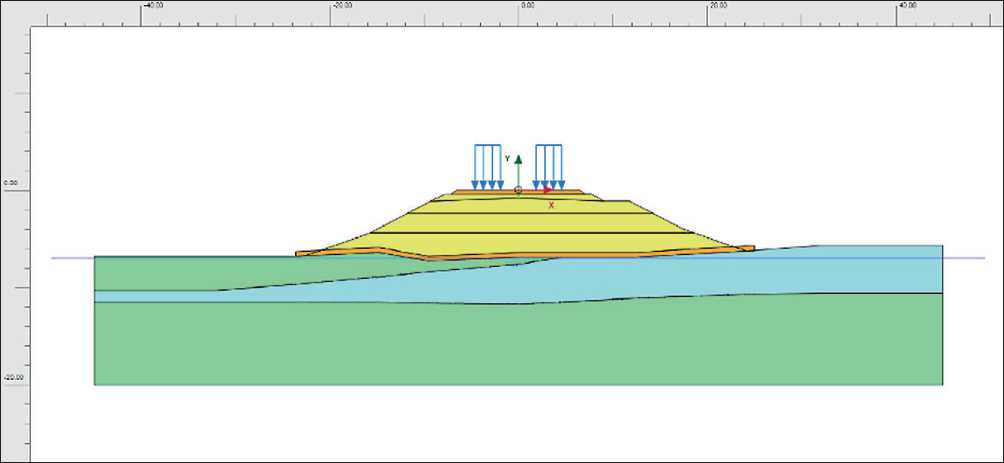
Table 1. Physical and mechanical characteristics of materials
|
Characteristics |
Name |
|||
|
Parameter |
Notation |
Unit of Measurement |
Crushed Stone (Material for Soil Columns) |
Soil-Cement Elements |
|
Specific Weight of Dry Soil |
g |
kN/m3 |
19 |
18 |
|
Specific Weight of Saturated Soil |
g |
kN/m3 |
19 |
|
|
Modulus of Deformation (for sandy soils) |
Е |
МPа |
38 |
900 |
|
Modulus of Deformation (for clayey soils) |
200 |
|||
|
Poisson’s Ratio |
u |
– |
0.3 |
0.25 |
|
Cohesion |
С |
МPа |
0.001 |
1.2 |
|
Angle of Internal Friction |
j |
degr |
40 |
26 |
|
Filtration Coefficient |
k |
m/day |
100 |
0 |
Fig. 1. Two-dimensional model of the embankment for the Object (developed by the authors)
-
– Load from the weight of the soil mass;
-
– Self-weight of structures;
-
– Loads from railway rolling stock (C14).
The standard temporary vertical load from railway rolling stock (C14) is applied in the form of encompassing maximum equivalent loads ν, кН/м; the load magnitude is assumed to be 50.85 kPa (5.15 tf/m²) over a strip 2.7 m wide (length of sleepers).
In modeling and calculating the stress-strain state (SDS) of the “structure – foundation – reinforced foundation” system, the following stages of construction were considered:
-
1. Stage 0 – Before the start of construction works (determination of initial stresses);
-
2. Stage 1 – Installation of soil-cement elements;
-
3. Stage 2 – Construction of the embankment;
-
4. Stage 3 – Load from railway tracks;
-
5. Stage 4 – Stability assessment of the embankment.
RESULTS AND DISCUSSION
Fig. 3 shows the general view of the computational model on the natural foundation of the Object.
Fig. 4 shows the shear deformations of the subgrade on the natural foundation of the Object.
As can be seen, near-critical stresses arise at the base of the embankment slopes under loading, which could negatively impact the condition of the structure during operation.
Table 2. Physical and mechanical characteristics of engineering-geological elements for the Object
|
Characteristics |
Name |
||||||
|
Parameter |
с о (Я *• о Z |
*1 с ф £ ф <л <0 ф 2 ч-О ** С э |
5 "о С 5 —- « О Ф « 5 и .У ■С о> « □ о. |
£ <0 о с <0 сл СЛ С о |
"О с <0 сл С ф N О bi ч- 15 "о VI |
"О С <0 М 4-1 с £ ю 2 С 5 Е ф ф 2 |
= 5 “ 2 ё 3 <л ъС ф И Ф “ "—" <л и |
|
Specific Weight of Dry Soil |
g |
kN/m3 |
18.5 |
15.2 |
20.4 |
18 |
19 |
|
Specific Weight of Saturated Soil |
g |
kN/m3 |
19.5 |
19.0 |
20.4 |
20 |
|
|
Modulus of Deformation (Young’s modulus) |
Е |
МPа |
8 |
2.6 |
35 |
40 |
36 |
|
Poisson’s Ratio |
u |
– |
0.35 |
0.34 |
0.3 |
0.3 |
0.3 |
|
Cohesion |
С |
МPа |
0.01 |
0.043 |
0.006 |
0.002 |
0.02 |
|
Angle of Internal Friction |
j |
degr |
8 |
11.4 |
30 |
38 |
40 |
|
Filtration Coefficient |
k |
m/day |
0.1 |
0.3 |
0.001 |
16 |
100 |
SYSTEM SOLUTIONS FOR TECHNOLOGICAL PROBLEMS
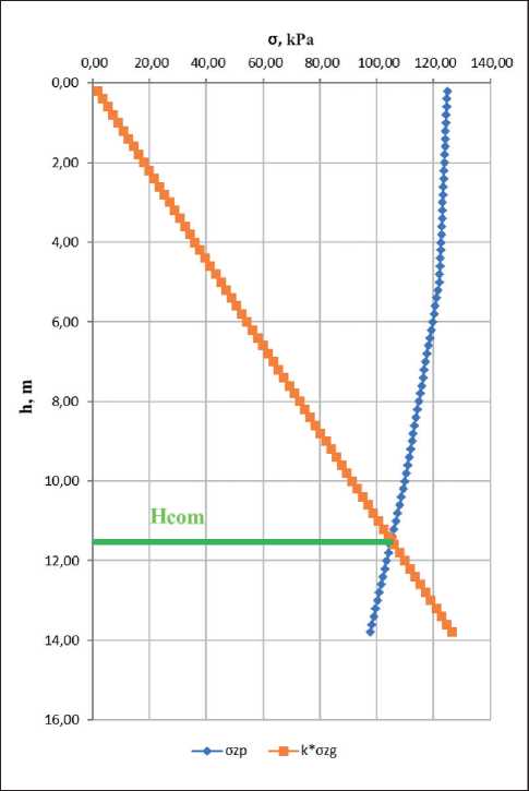
Fig. 2. Graph for determining the depth of the compressible soil layer based on the main condition for the Object (developed by the authors)
Based on the calculations of the factor of safety using the Mohr-Coulomb model, a value of 1.251 was obtained, which is at the boundary of the normative value of 1.2 required for the stability of a railway embankment for a Category II line according to CR 238.1326000.2015 “Railway Track”. It was shown in [18] that this model may overestimate the factor of safety. Therefore, further in the article, reinforcement options for this structure are presented.
The “Undrained A” mode was used in the calculations, during which excess pore pressures are generated in the foundation. The duration of each loading stage was taken into account by correlating the calculation stages with the construction schedule
The “Undrained A” behavior type is a universal mechanism that allows for both unstabilized and stabilized strength to be considered. The transition from one state to another occurs during filtration consolidation.
Table 3 outlines the staged construction process of the embankment.
Soil-cement elements are installed to a depth of 8.2 m, with a diameter of 1000 mm and a spacing of 1800×1800 mm. Fig. 5 shows the general view of the computational model using soil-cement elements at the Object.
SYSTEM SOLUTIONS FOR TECHNOLOGICAL PROBLEMS
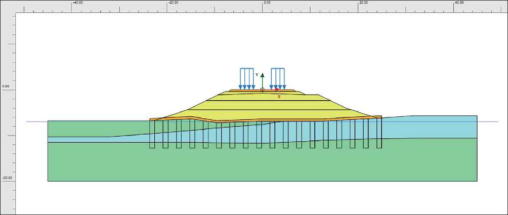
Fig. 3. General view of the computational model of the embankment on the natural foundation of the Object (developed by the authors)
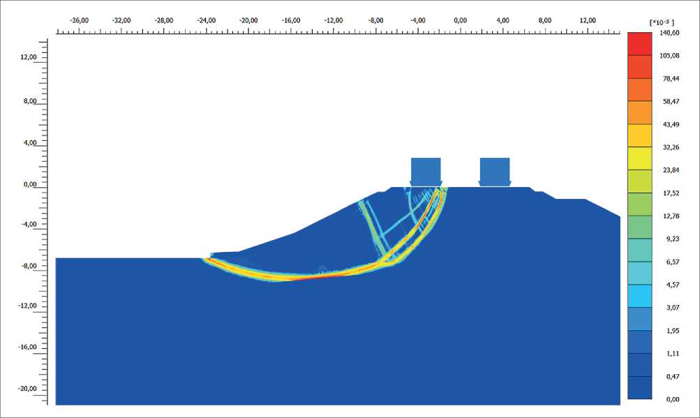
Fig. 4. Shear deformations on the natural foundation of the Object (developed by the authors)
Fig. 6 shows the shear deformations obtained as a result of applying the soil-cement element foundation reinforcement technology. As can be seen, stress attenuation occurs at the base of the embankment slope under loading, compared to the construction variant without reinforcement (see Fig. 4), which leads to stabilization of the foundation in its slope area.
Vertical crushed stone columns are installed to a depth of 8.2 m, with jet diameters of 800 mm and spacing of 1900×2200 mm. Fig. 7 shows the general view of the computational model with the installation of vertical crushed stone columns at the studied section of the NLR.
Fig. 8 shows the shear deformations obtained as a result of applying the vertical crushed stone column foun-
SYSTEM SOLUTIONS FOR TECHNOLOGICAL PROBLEMS
Table 3. Stages of construction
|
Stage, № |
Description |
Time Interval |
Type of Calculation |
Comment |
|
1 |
Construction of the embankment. Stage 1 |
2 days |
Consolidation |
– |
|
2 |
Consolidation due to embankment construction |
15 days |
Consolidation |
– |
|
3 |
Construction of the embankment. Stage 2 |
2 days |
Consolidation |
– |
|
4 |
Consolidation due to embankment construction |
15 days |
Consolidation |
– |
|
5 |
Load from railway rolling stock (С14) |
0,2 days |
Consolidation |
– |
|
6 |
Consolidation after load application |
From the calculation |
Consolidation |
Dissipation of pore pressure to 1 kN/m2 |
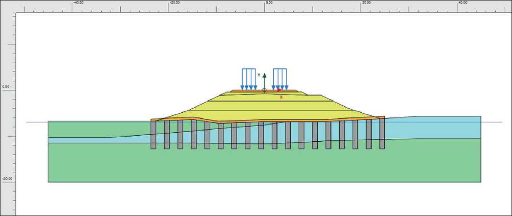
Fig. 5. General view of the computational model of the embankment with soil-cement elements in the foundation at the Object (developed by the authors)
dation reinforcement technology. Similarly to the use of soil-cement elements (see Fig. 6), it can be seen that stress attenuation occurs at the base of the embankment slope under loading, compared to the variant without reinforcement using vertical crushed stone columns (see Fig. 4), which leads to stabilization of the foundation in the slope area.
Fig. 9 shows the graph of the dependence of vertical displacements at different stages of embankment construction, taking into account the applied load from rolling stock. Three variants of soil foundation reinforcement are analyzed:
-
• Case 1 – Natural foundation;
-
• Case 2 – Installation of soil-cement elements in the foundation;
-
• Case 3 – Installation of vertical crushed stone columns in the foundation.
Fig. 10 shows a diagram of the distribution of obtained stability factors for the embankment slope relative to the normative value (indicated by the red line), depending on the foundation reinforcement technology used for high-temperature permafrost soils.
CONCLUSION
By analyzing the results of numerical modeling of the SDS for the studied section of the Obskaya–Salekhard– Nadym railway line of the Northern Latitudinal Railway, it can be concluded that the stability of the embankment increases with the application of two foundation rein-
SYSTEM SOLUTIONS FOR TECHNOLOGICAL PROBLEMS
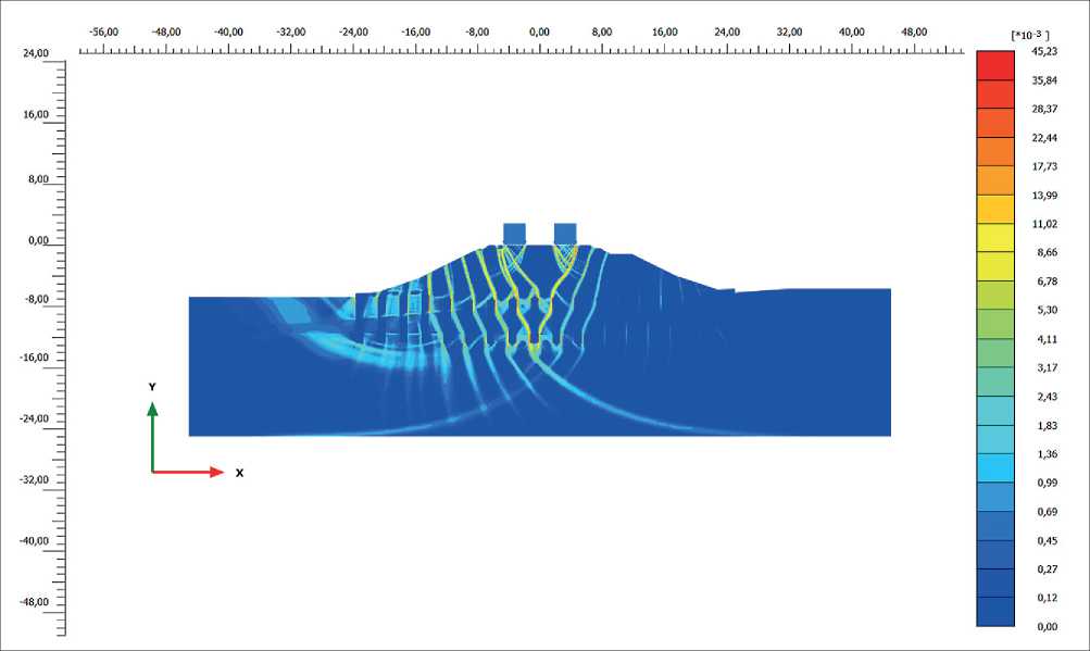
Fig. 6. Shear deformations with soil-cement elements in the foundation at the Object (developed by the authors)
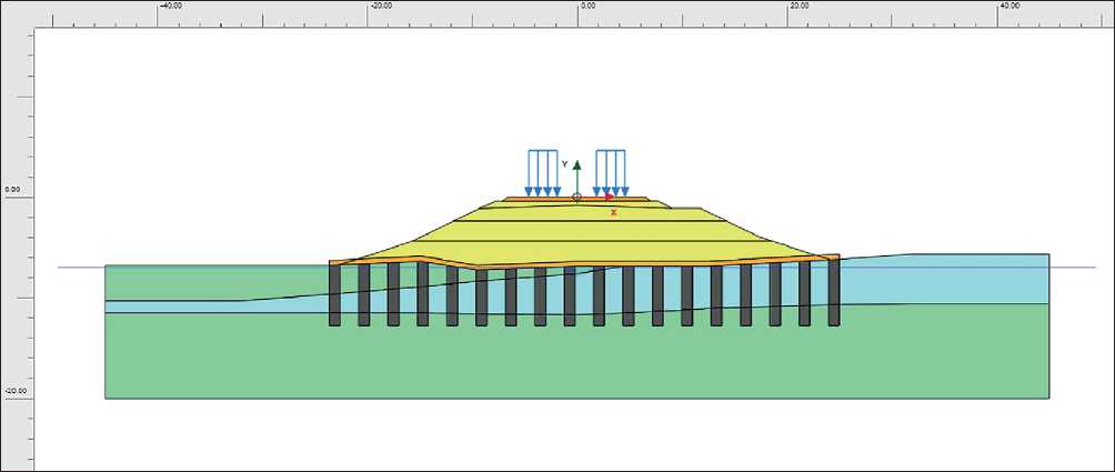
Fig. 7. General view of the computational model of the embankment with vertical crushed stone columns in the foundation at the Object (developed by the authors)
forcement technologies: jet grouting and vertical crushed stone columns.
It has been demonstrated that the use of jet grouting provides the highest structural stability, reducing settlement and increasing the factor of safety to acceptable levels. For instance, analyzing the graphs of vertical displacement dependence at different stages of embank- ment construction (Fig. 9), it is evident that vertical displacements decreased from 38 cm (natural foundation) to 22 cm when using soil-cement elements. The factor of safety (Fig. 10) increased from 1.251 to 1.446, which meets regulatory requirements.
Reinforcement of the soil foundation using vertical crushed stone columns also improves stability indicators,
SYSTEM SOLUTIONS FOR TECHNOLOGICAL PROBLEMS
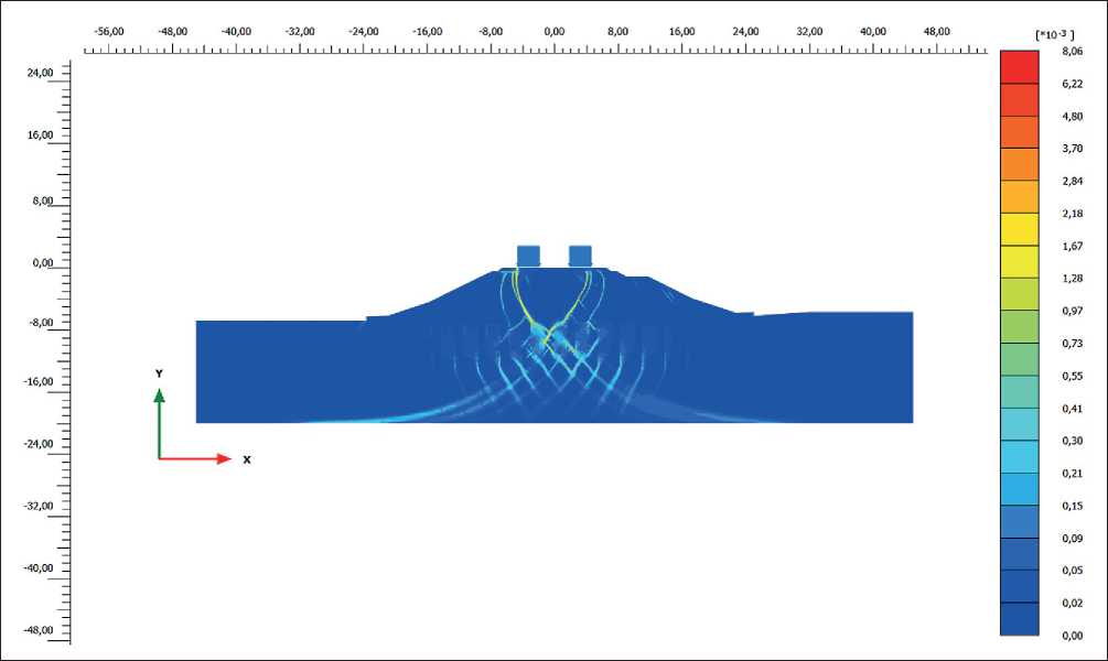
Fig. 8. Shear deformations with vertical crushed stone columns in the foundation at the Object (developed by the authors)
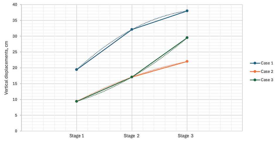
Fig. 9. Dependence of vertical displacements at different stages of embankment construction for the applied foundation reinforcement technologies in high-temperature permafrost soils: Stage 1 – Construction of the first embankment layer with subsequent consolidation; Stage 2 – Construction of the second embankment layer with subsequent consolidation; Stage 3 – Accounting for rolling stock load with subsequent consolidation (developed by the authors)
SYSTEM SOLUTIONS FOR TECHNOLOGICAL PROBLEMS
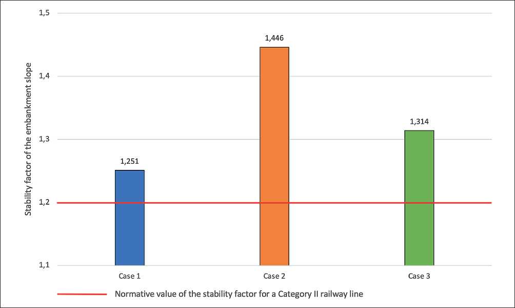
Fig. 10. Stability factor of the embankment slope depending on the foundation reinforcement technology for high-temperature permafrost soils (developed by the authors)
but to a lesser extent compared to jet grouting: vertical displacements amounted to 29.5 cm, and the factor of safety increased to 1.314. An advantage of this reinforcement method is the absence of the need to determine the heat released during construction and installation works when implementing this technology, which enhances its versatility and practical applicability.
Overall, the proposed foundation soil reinforcement technologies improve the reliability of structures built on them, particularly the embankment. The choice of foundation soil reinforcement technology should be based on an analysis of specific construction and operational
conditions of the object – natural, technical, technological, and economic factors.
It can be noted that in similar engineering-geological conditions, as described in this study, jet grouting is suitable for reinforcing foundation soils in areas with high stability and bearing capacity requirements, but with mandatory preliminary selection of the cement slurry and analysis of its exothermic behavior during strength gain. Vertical crushed stone columns, as a method of soil reinforcement, represent a promising structural and technological solution, especially for less heavily loaded sections.
