Assessment of the relationship between the initial temperature of concrete and the time intervals between layers of concrete placement to control early thermal cracking

Author: Le V.H., Nguyen T.C, Hoang Q.L., Aniskin N.A.
Journal: Nanotechnologies in Construction: A Scientific Internet-Journal @nanobuild-en
Section: Construction materials science
Article in issue: 4 Vol.17, 2025.
Free access
Introduction. This article presents the results of a study on the development of a concrete mix incorporating fly ash, blast furnace slag, a superplasticizer, and a temperature-rise inhibitor to produce concrete with a compressive strength of 60 MPa after 28 days. The concrete mixture is intended for use in a massive concrete foundation measuring 4 meters by 4 meters by 4 meters. Methods and materials. Laboratory tests were conducted to determine the compressive and tensile strength of the concrete. Additionally, tests were performed to evaluate the temperature rise under adiabatic conditions. Results. Using numerical simulation, the study investigated the influence of two factors on the temperature regime for the given concrete composition, Vietnamese climatic conditions, and the selected mass concrete structure: the temperature of the placed concrete and the time interval between the placement of adjacent blocks forming the mass. Discussion. Based on the requirement that the temperature difference between the center and the surface of the concrete mass should not exceed the permissible limit of 20 °C, an equation has been derived relating these two factors. Graphs of the corresponding functions have also been constructed. Conclusion. The research results can serve as practical guidelines for the construction of monolithic concrete foundations, helping to minimize the risk of thermal cracking and ensure the durability and quality of the structure.
Mass concrete, thermal cracking, temperature difference, maximum temperature, temperature rise inhibitor (TRI)
Short address: https://sciup.org/142245493
IDR: 142245493 | DOI: 10.15828/2075-8545-2025-17-4-389-400
Text of the scientific article Assessment of the relationship between the initial temperature of concrete and the time intervals between layers of concrete placement to control early thermal cracking
Original article
Ле В.Х., Нгуен Ч.Ч., Хоанг К.Л., Анискин Н.А. Оценка взаимосвязи между начальной температурой бетона и интервалами послойной укладки бетонного массива для контроля раннего термического трещинообразования. Нанотехнологии в строительстве. 2025;17(4):389–400. – EDN: BLGUCT.
Mass concrete structures are widely used in the construction industry worldwide. According to ACI 207.1R-96, mass concrete is defined as any volume of concrete large enough to require measures to control the heat of cement hydration and associated volume changes to minimize cracking [1]. In Vietnam, TCVN 9341:2012 (Mass Concrete – Construction and Acceptance) defines a mass concrete structure as having a minimum size of 2 meters in both width and height [2]. The construction of mass concrete structures must ensure that the design requirements for concrete in terms of strength, density, and water resistance are met, and that thermal cracking caused by the heat of cement hydration in the early stages after concrete placement is prevented.
In conventional concrete structures, most of the heat released during cement hydration is rapidly dissipated into the environment through the surfaces of the structure. The time required for complete heat dissipation depends on the thickness of the structure. For example, a 150 mm thick concrete element can reach thermal equilibrium in about 0.5 hour after casting, whereas a 1.5 m thick structure may require about a week and a 15 m thick structure may require up to two years [3]. The temperature difference between the center of the mass and its surface in non-massive concrete elements is usually small, which reduces the risk of thermal cracking. In contrast, in massive concrete structures, the heat from hydration dissipates more slowly, resulting in a significant temperature gradient between the center and the surface of the structure. An increase in the temperature of the core causes its expansion, while the surface, exposed to lower ambient temperatures, undergoes limited deformation and tends to contract. Such differential temperature effects can cause thermal tensile stresses. If the tensile stress exceeds the tensile strength of concrete, thermal cracking may occur.
Cracks in massive concrete structures are generally classified into three categories: through cracks, deep cracks, and surface cracks [4]. These cracks compromise the safety, integrity, and durability of the structure and are often difficult to repair. Therefore, implementing effective measures to prevent thermal cracking in massive concrete elements is of critical importance. Currently, such measures can be divided into three main groups: optimization of the concrete mix design, structural measures aimed at reducing crack formation, and technological measures for optimizing the construction process of massive concrete structures [5]. During construction, achieving a favorable temperature and thermal stress state can be accomplished by selecting appropriate concrete placement parameters, such as the initial temperature of the concrete mix, as well as the thickness and intensity of its placement. Structural measures may include insulating the exposed surfaces of the structure and dividing the total volume of massive concrete into separate blocks [6].
Numerous studies and concrete construction practices have demonstrated that controlling the initial temperature of the concrete mix is an effective method for reducing the risk of thermal cracking in massive concrete structures. Cooling of the concrete mix can be achieved by chilling the aggregates and mixing water, partially replacing the mixing water with ice, or using liquid nitrogen.
CONSTRUCTION MATERIAL SCIENCE
The impact of the aforementioned measures on the thermal behavior of massive concrete structures under Vietnam’s climatic conditions has been examined in numerous studies. In [7], numerical modeling of cement hydration heat using Midas Civil 2019 software demonstrated that increasing the initial concrete temperature from 15 to 30 °C significantly raises the risk of thermal cracking. In studies [8–9], a thermal analysis was conducted using an experimental approach to mix design, along with the development of a mathematical model describing the relationship between cement content, initial temperature, and the maximum internal temperature of the concrete mass. The results indicated that both the initial temperature and the cement content have a significant influence on temperature rise and the potential for thermal cracking.
Studies in [10–12] evaluated the effectiveness of thermal crack control through the construction of concrete masses in layers of varying thickness. The analysis revealed that the thickness of the placed layer has a significant impact on the formation of thermal cracks. As the layer thickness increases, the maximum internal temperature of the concrete mass also rises. To reduce the temperature difference between the center of the mass and its surface, surface insulation can be employed as a mitigation measure [13].
Several studies have investigated the influence of construction-phase factors on the risk of thermal cracking in massive concrete structures. However, these studies did not examine the relationship between the initial temperature of the concrete mix and the interval between pouring stages in the context of thermal crack control. In practice, the selection of appropriate crack control measures should be aligned with the specific requirements of the project, including economic considerations, construction schedule, and construction technology. In many cases, effective thermal crack control requires the combined application of a comprehensive set of measures.
The present study aims to establish the relationship between two critical factors influencing the risk of thermal cracking–namely, the initial temperature of the concrete mix and the time interval between successive concrete layer placements. Optimizing these parameters can reduce the temperature gradient between the core of the concrete mass and its surface, thereby minimizing the risk of thermal cracking in massive concrete structures.
The conducted studies examined the thermal behavior of the placed concrete mass, taking into account the exothermic nature of cement hydration. In the numerical experiment, two variables were considered: the temperature of the placed concrete mix and the time interval between the placement of concrete layers. As a result of the numerical analysis, the maximum internal temperature of the concrete mass and the maximum temperature difference between the core and the surface of the structure were determined. The dependencies of the maximum temperature on the considered factors were obtained. Additionally, an equation was derived relating these factors based on the condition that the maximum allowable temperature difference between the core and the surface of the mass does not exceed 20 °C.
The numerical experiment was conducted using the finite element method with the software package Midas Civil 2019. A comprehensive set of laboratory tests was performed for the concrete mix used in the construction to determine its physical and mechanical properties, as well as the heat evolution profile over time under adiabatic conditions.
MATERIALS AND METHODS
The object of the study was a structure in the form of a mass concrete with dimensions (a×b×h) = (4×4×4) m. The structure is located on a foundation with dimensions [2a×2b×(h/2)] = (8×8×2) m. It is assumed that the structure is erected in typical Vietnamese climatic conditions with an average ambient temperature of 25 °C. The initial temperature of the foundation is assumed to be 20 °C.
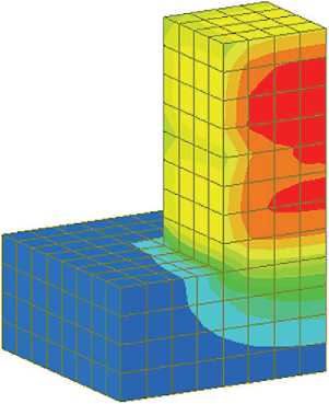
Due to the two-dimensional symmetry of the concrete block and to reduce the analysis volume, 1/4 of the model was used for the structural analysis. The dimensions of the concrete block and the finite element model are shown in Figure 1.
The concrete for the structure under consideration, in addition to cement and aggregates, includes fly ash, crushed granulated blast furnace slag, superplasticizer, and temperature rise inhibitor (TRI) additive. Detailed proportions of the mixture are presented in Table 1.
Cement. The cement used was But Son PC40 Portland cement, which meets the criteria of the Vietnamese standard TCVN 2682-2020 [14]. The physical and mechanical properties are given in Table 2.
Fly ash. The use of Pha Lai fly ash type F meets the requirements of the Vietnamese standard TCVN 10302:2014 “Active fly ash admixtures for concrete, mortar and cement” [15]. Fly ash has a specific gravity of 2.35 g/cm³, a specific surface area of 0.58 m²/g, and a dry mass density in a compacted state of 1480 kg/m³.
Finely ground granulated blast furnace Slag. Hoa Phat S95 is used, which meets the requirements of the Vietnamese standard TCVN 11586:2016 “Finely ground granulated blast furnace slag for concrete and mortar” [16]. Slag S95 has a density of 2.92 g/cm³, a specific surface area of 0.37 m²/g, and a mass density in a dry compacted state of 1450 kg/m³. The chemical composition of the concrete mix components is presented in Table 3.
The temperature rise inhibitor (TRI). Used in this study is an organic dextrin-based polymer blend produced by Guangzhou Huakeli Building Materials Co., Ltd. It is
CONSTRUCTION MATERIAL SCIENCE
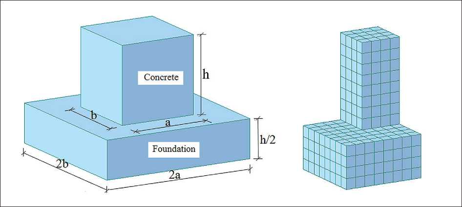
Fig. 1. Calculation scheme and division of the finite element grid into 1/4 of the structural model
Table 1. Composition of concrete mix
|
Concrete mix |
Cement (kg/m3) |
Fly ash (kg/m3) |
Blast furnace slag (kg/m3) |
Sand (kg/m3) |
Crushed stone (kg/m3) |
Water (l/ m3) |
Superplasticizer (kg/m3) |
TRI (kg/m3) |
|
302.3 |
38.4 |
129.3 |
763.6 |
1001 |
164 |
4.7 |
3.06 |
Table 2. Physical and mechanical properties of Portland cement PC 40 But Son
|
Specific gravity, g/cm3 |
Fineness of grinding |
Concrete hardening time, minutes |
Cement strength, MPa |
Standard consistency, % |
|||
|
Screening residue 0.09 mm, % |
Surface area, cm2/g |
Initial recruitment time |
Time for the final set |
3 day |
28 day |
||
|
3.15 |
5.5 |
3640 |
115 |
360 |
28.5 |
50.8 |
30.5 |
Table 3. Chemical composition of cement, fly ash and finely ground granulated blast furnace slag, %
Superplasticizer. The superplasticizer selected for use in this study was MasterGlenium SKY 8613. The recommended dosage is 0.5 to 2.0 liters per 100 kg of binder, and the typical dosage is 1.0 to 1.8 liters per 100 kg of binder.
Crushed rock and sand. The crushed rock from Phu Ly quarry in Ha Nam was used in the experiment. The aggregate has a particle size in the range of (5–20) mm, a density of 2.72 g/cm³, and a compacted mass density of 1.69 g/cm³.
The sand used in this study was Song Lo yellow sand with a fineness modulus (MK) of 2.47 and a density of 2.62 g/cm³. Its compacted mass density was 1.65 g/cm³.
CONSTRUCTION MATERIAL SCIENCE
Laboratory studies of physical and mechanical characteristics of concrete
The grading of concrete mixtures was determined in accordance with ACI 211.1-91 (USA) [17]. Concrete specimens were cast and cured in accordance with the Vietnamese standard TCVN 3105:2022 “Concrete Mixtures and Concrete – Sampling, Making and Curing of Test Specimens” [18].
Compressive strength was tested according to TCVN 3118:2022 using 150×150×150 mm cube specimens [19].
The splitting tensile strength was tested based on TCVN 3120:2022 using 150×300 mm cylindrical specimens and the results were converted to equivalent values for standard 150×150×150 mm cubic specimens using the conversion factor [20].
The concrete mixture in this study was designed to achieve a compressive strength of 60 MPa after 28 days using standard cubic specimens (150×150×150 mm). However, since ACI 211.1-91 provides recommendations for mix design based on cylindrical specimens (150×300 mm), the conversion factor from cube strength to cylinder strength as specified in Vietnamese standard TCVN 3118:2022 was applied in the mix design process.
Twelve concrete cubes (150×150×150 mm) were cast for compressive strength testing at four curing ages: 3, 7, 28 and 56 days, with three specimens tested at each age.
The compression testing procedure is illustrated in Figures 2a, b and the results are summarized in Table 4.
For the splitting tensile strength test, twelve cylindrical specimens (150×300 mm) were prepared and divided into the same four age groups, with three specimens in each group. The testing procedure is shown in Figures 2c, d. The measured tensile strength values were then converted into equivalent cube strength values (150×150×150 mm) using the appropriate conversion factor, and the results are also presented in Table 4.
The experiment to determine the adiabatic temperature rise of the concrete mixture
The adiabatic temperature rise was measured in accordance with GOST 24316-2022 “Method for determining the heat released during concrete hardening” [22]. The device used for measuring the adiabatic temperature in this study was developed based on the model proposed by Yun Lin and Hong Liang Chen [21,23], with two functional enhancements.The first, a 3 cm thick layer of foamed rubber was added to the insulation chamber to minimize evaporation and improve thermal insulation. The second, a remote monitoring and data acquisition function was integrated, enabling access to the data via mobile phones or computers through a network connection, eliminating the need for constant physical connection to the measuring device.

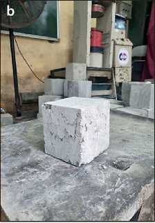
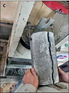
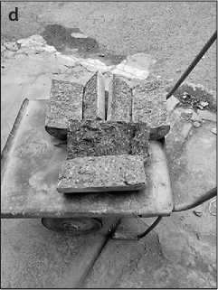
Fig. 2. Experiment to determine the compressive and tensile strength of concrete: a) testing the compressive strength of concrete; b) crack shape of a concrete compression specimen; c) testing the tensile strength of concrete; d) results of tensile tests of concrete samples
Table 4. Compressive strength, tensile strength and modulus of elasticity of concrete at different ages
|
Age, days |
3 |
7 |
28 |
56 |
Note |
|
Compressive strength, MPa |
34.8 |
49.98 |
61.34 |
73.97 |
Experiment |
|
Tensile strength, MPa |
3.09 |
4.02 |
4.72 |
6.09 |
Experiment |
|
Modulus of elasticity, GPa |
31 |
37.05 |
40.98 |
44.93 |
Calculation based on concrete compressive strength [21] |
Table 5. Adiabatic increase in temperature over time
|
Time, day |
0.5 |
1.0 |
1.5 |
2.0 |
2.5 |
3.0 |
3.5 |
4.0 |
5.0 |
|
Adiabatic temperature rise, oC |
3.1 |
28.3 |
46.8 |
52.4 |
53.5 |
53.6 |
53.6 |
53.6 |
53.6 |
CONSTRUCTION MATERIAL SCIENCE
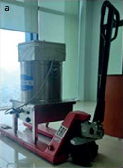
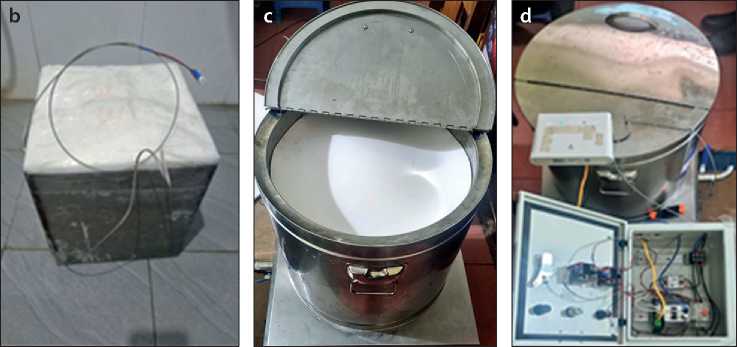
Fig. 3. Experimental measurement of the temperature of concrete mixture during an adiabatic process: a) adiabatic device for measuring temperature; b) adiabatic measurement of the temperature of a concrete sample; c) pouring the mixture into the device; d) the process of measuring the temperature of the adiabatic process
The apparatus and measurement procedure are shown in Figure 3, and the results of the adiabatic temperature rise are presented in Table 5.
Determination of the temperature field in monolithic concrete structures
In this study, the casting of the concrete structure was simulated in two stages using blocks with a height of h/2 = 2 meters (Figure 4). The influence of two factors on the thermal regime was investigated: the time interval between
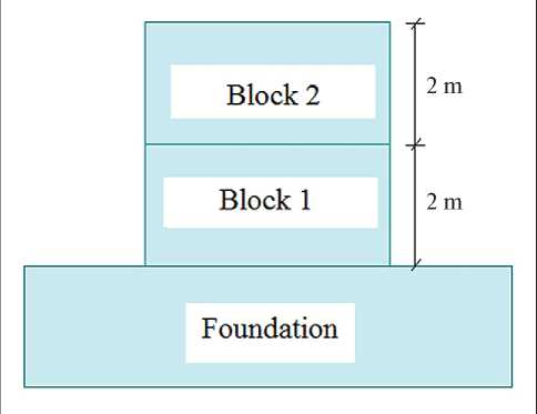
Fig. 4. Scheme of the stage of pouring a concrete foundation block the placement of the blocks and the initial temperature of the concrete mixture. Six time interval scenarios were considered: 1, 2, 3, 5, 6, and 7 days (corresponding to cases 1 through 6, respectively).
According to ACI 207.1R-96 [1], conventional cooling methods can reduce the initial temperature of a concrete mixture by approximately 10 °C. When further temperature reduction is required, the use of liquid nitrogen spray technology is recommended. In cases where concrete is mixed at a batching plant and transported to the construction site, the initial casting temperature is typically about 5 °C higher than the ambient temperature [4].
Assuming an ambient air temperature of 25 °C, which corresponds to typical climatic conditions in Vietnam. This study considered four initial concrete mixture temperature scenarios: 15, 20, 25, and 30 °C. The mechanical and physical properties of the materials used in the numerical experiment are given in Table 6.
RESULTS AND DISCUSSION
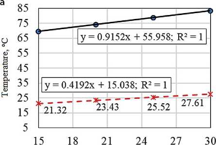
The results of the numerical simulation for determining the maximum temperature and the maximum temperature difference between the center and the surface of the structure are presented in Figure 5 and Table 7.
The results indicate that an increase in the initial temperature of the concrete leads to higher maximum temperatures and greater temperature differentials, whereas an increase in the time interval between placements has the opposite effect, reducing both values. In all six scenarios,
CONSTRUCTION MATERIAL SCIENCE
Initial temperature of concrete mixture, °C
О Maximum temperature (°C)
Ж Maximum temperature difference (°C)
c
p о s
Initial temperature of concrete mixture. °C
О Maximum temperature (°C)
ж Maximum temperature difference (°C)
Initial temperature of concrete mixture, °C О Maximum temperature (°C)
Ж Maximum temperature difference (°C)
Initial temperature of concrete mixture. °C
О Maximum temperature (°C)
ж Maximum temperature difference (°C)
Table 6. Mechanical and physical properties of materials
|
Material parameters, units |
Value |
|
|
Concrete |
Foundation |
|
|
Thermal conductivity, W/(m•oC) |
2.70 |
2.00 |
|
Specific heat capacity, kJ/(kg•oC) |
1.15 |
0.84 |
|
Specific gravity, kg/m3 |
2357 |
1800 |
|
Convective heat transfer coefficient, W/(m2•oС) |
13.94 |
14.00 |
|
Modulus of elasticity, N/m2 |
Table 4 |
1.8×10¹⁰ |
|
Coefficient of thermal expansion, α |
10.5×10⁻⁶ |
10×10–6 |
|
Poisson’s ratio |
0.167 |
0.20 |
|
Cement content, kg/m3 |
329 |
– |
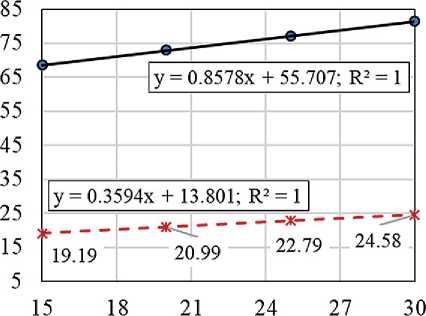
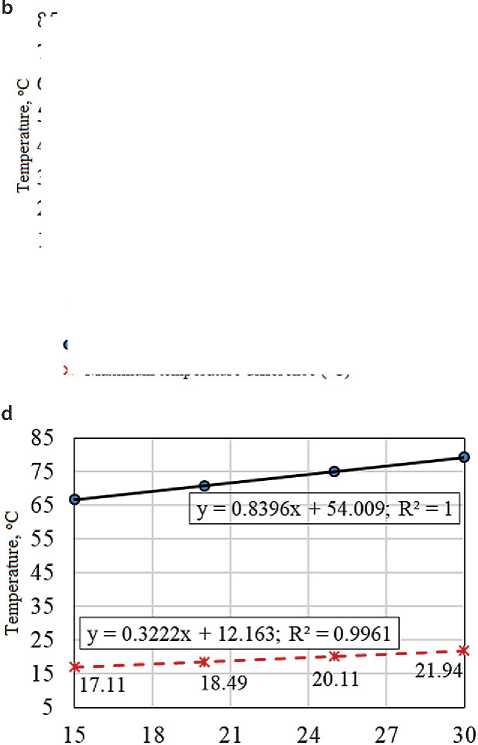
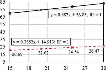
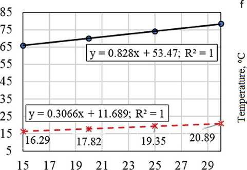
Fig. 5. Graph of the maximum temperature in the center, the maximum temperature difference between the center and the surface of the structure in the cases considered: а) case 1; b) case 2; c) case 3; d) case 4; e) case 5; f) case 6
CONSTRUCTION MATERIAL SCIENCE
e
2 a
1>
Initial temperature of concrete mixture, °C Maximum temperature (°C)
Initial temperature of concrete mixture, °C
О Maximum temperature (°C)
ж Maximum temperature difference (°C)
О ж
Maximum temperature difference (°C)
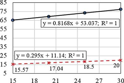
Fig. 5. The End the maximum temperature difference exceeds 20°C for certain initial concrete temperatures, indicating a potential risk of thermal cracking in the massive concrete structure. Using the obtained regression equations for each of the six placement interval scenarios, the initial concrete temperature that ensures the critical temperature differential limit of 20 °C was determined. The corresponding results are presented in Table 8 and Figure 6.
Thus, the relationship between the initial temperature of the concrete mixture and the interval between two concrete placements, ensuring that the maximum temperature difference between the center and the surface of the
concrete block does not exceed 20 °C, can be expressed by a first-order equation in the form of Equation (1):
y = 0.3112 x –2.4167 with R2 = 0.9929 (1)
where: y is the time interval between concreting of blocks, days; x is the initial temperature of the concrete mix, °C.
Equation (1) is defined as a monotonically increasing function. In construction practice, the variables considered factors x and y affect the course and economy of construction. They strive to minimize the construction
Table 7. Maximum temperature, maximum temperature difference between the center and the surface of the structure in the examined cases
|
Case (interval) |
Result |
Initial temperature of concrete mix (oC) |
|||
|
15 |
20 |
25 |
30 |
||
|
1 (1 day) |
Maximum temperature (oC) |
69.69 |
74.27 |
78.84 |
83.41 |
|
Maximum temperature difference (oC) |
21.32 |
23.43 |
25.52 |
27.61 |
|
|
2 (2 day) |
Maximum temperature (oC) |
70.08 |
74.49 |
78.9 |
83.31 |
|
Maximum temperature difference (oC) |
20.69 |
22.62 |
24.54 |
26.47 |
|
|
3 (3 day) |
Maximum temperature (oC) |
68.58 |
72.86 |
77.14 |
81.45 |
|
Maximum temperature difference (oC) |
19.19 |
20.99 |
22.79 |
24.58 |
|
|
4 (5 day) |
Maximum temperature (oC) |
66.61 |
70.79 |
75.00 |
79.20 |
|
Maximum temperature difference (oC) |
17.11 |
18.49 |
20.11 |
21.94 |
|
|
5 (6 day) |
Maximum temperature (oC) |
65.89 |
70.03 |
74.17 |
78.31 |
|
Maximum temperature difference (oC) |
16.29 |
17.82 |
19.35 |
20.89 |
|
|
6 (7 day) |
Maximum temperature (oC) |
65.29 |
69.37 |
73.46 |
77.54 |
|
Maximum temperature difference (oC) |
15.57 |
17.04 |
18.50 |
20.00 |
|
CONSTRUCTION MATERIAL SCIENCE
Table 8. Initial temperatures of concrete mix providing a temperature difference between the center and surface of a concrete block of 20 °C
|
Cases |
The initial temperature of the concrete mixture ensures a temperature difference between the center and the surface of the concrete block of 20 °C |
|
1 |
20 = 0.4192 a +15.038 → a = 11.84 (oC) |
|
2 |
20 = 0.3852 a +14.913 → a = 13.821 (oC) |
|
3 |
20 = 0.3594 a +13.801 → a = 17.25 (oC) |
|
4 |
20 = 0.3222 a +12.163 → a = 24.32 (oC) |
|
5 |
20 = 0.3066 a +11.689 → a = 27.11 (oC) |
|
6 |
20 = 0.295 a +11.14 → a = 30 (oC) |
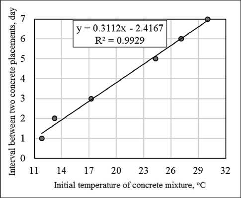
Fig. 6. Dependence of the initial temperature of the concrete mixture on the time interval between two concrete pours with a maximum temperature difference between the center and the surface of the concrete mass equal to 20 °C
time, i.e. reduce y, and also limit the need for cooling the material to reduce costs, i.e. maintain x at a higher level. In possible scenarios where there is a risk of thermal cracking, it is possible to determine the dominant influencing factor under certain conditions and adjust the other variable accordingly based on equation (1).
To illustrate the use of the obtained results, let us consider two examples.
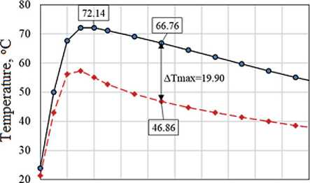
Example 1: Let us assume that the expected interval between laying concrete blocks is y = 4 days. Based on equation (1), we determine that the initial temperature of the concrete mix to ensure an acceptable temperature difference of 20 °C is x ≈ 21 °C. The results of the numerical solution of this considered scenario ( y = 4 days, x = 21 °C) are shown in Figure 7. They confirm the correctness of the
obtained dependencies. For this considered scenario, with the accepted time interval between laying concrete blocks y = 4 days, to minimize the risk of temperature cracking, it is necessary to lay the concrete mix with a temperature no higher than 21 °C.
Example 2: Let us assume that the initial temperature of the concrete mix is x = 28.5 °C. Based on equation (1), the time interval between batches of concrete can be determined to prevent thermal cracking as y = 6.5 days. The results of the numerical solution for this scenario ( x = 28.5 °C, y = 6.5 days), confirming the correctness of the
а
TEMPERATURE
_ 72.14
€7.40
---I- €2.6€
-- 57.92
-- 53.18
-- 43.44
-- 43.70
---38.9€
-- 34.22
-- 29.43
-- 24.74
^®Ln/Max Stags, oo
HYDRATION HY STEP (MAX)
MAX : 742
MIN : 2
FILE: HOI THAO DOT
UNIT: C
DATE: 05/07/2025
b
12 36 60 84 108 132 156 180 204 228 252
Time, hour
Temperature at core, °C
-♦-- Surface temperature, °C
Fig. 7. Distribution of the temperature field in a concrete massif (a) and the evolution of the temperature in the center and on the surface of a concrete block for scenario x = 21 oC and y = 4 days (b)
CONSTRUCTION MATERIAL SCIENCE
FILE: HOI THAO DOT
UNIT: C
DATE: 05/07/2025
TEMPERATURE
HYDRATION RY STEP (MAX) MAX : 823 MIN : 2
• Temperature at core, °C
-♦-- Surface temperature, °C
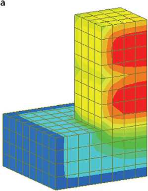
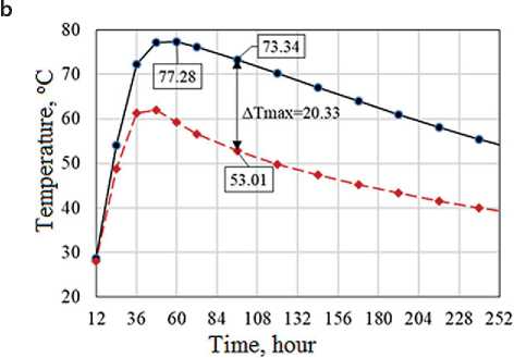
Fig. 8. Distribution of the temperature field in a concrete massif (a) and the evolution of the temperature in the center and on the surface of a concrete block for the scenario x = 28.5 oC and y = 6.5 days (b)
solution, are shown in Figure 8. For this scenario, with the adopted value of the temperature of the concrete being placed x = 28.5 °C, the time interval between the placement of concrete blocks should be at least y = 6.5 days. This will ensure the minimization of the risk of thermal cracking.
In cases where the desired temperature regime cannot be achieved through the selection of the initial concrete temperature and the time interval between block placements alone, or where such an approach is economically impractical, it is necessary to consider additional measures for temperature optimization.
CONCLUSION
Laboratory investigations were conducted for the selected concrete mix and its components to determine the physical and mechanical properties of the material, including the study of temperature rise under adiabatic conditions. The obtained properties were used as input parameters for the numerical simulation.
Based on the finite element method and using the Midas Civil 2019 software package, a study was con-
ducted to investigate the influence of factors such as the initial temperature of the concrete mixture and the time interval between block placements on the thermal behavior of a massive concrete structure. For the selected concrete mix and placement conditions (considering the climatic conditions of Vietnam), regression equations were derived to determine the maximum temperature at the center of the concrete mass and the maximum temperature difference between the center and the surface of the structure.
An additional equation was derived to describe the relationship between the initial temperature of the concrete mixture and the time interval between block placements, based on the condition that the temperature difference between the center and the surface of the massive concrete structure equals 20 °C – this being the maximum allowable limit to prevent thermal cracking.
The research results can be utilized by construction organizations to determine appropriate concrete placement parameters in order to mitigate the risk of thermal cracking in large-scale concrete structures during the early stages of construction.
