CAD/CAE Numerical Modeling of Fiber-Reinforced 3D Woven Composite Parts and their Machining Process

Author: Ekaterina Igorevna Shchurova, Igor Alexeevich Shchurov
Section: Механика
Article in issue: 1 т.18, 2026.
Free access
Edge tools, such as drills, milling cutters, and turning tools, are increasingly used in the manufacture of parts made of 3D woven fiber-reinforced composite materials. The cutting process of non-rigid workpieces, such as turbine blades, is accompanied by noticeable elastic displacements which reduce the machining accuracy. To calculate cutting forces, chip formation should be simulated in the cutting zone, which significantly depends on the orientation of the workpiece fibers relative to the wedge of the cutting tool. Since workpiece deformations should be calculated selectively at separate points of the toolpath, the corresponding fragments of the workpiece with the specific fiber arrangement should be determined for cutting modelling. For this purpose, we need to develop a finite element model of the entire workpiece taking into account fibers and boundary layers and calculate the stress-strain state in the cutting zone during chip formation in the selected workpiece fragments. This research allowed solving these issues. We obtained mathematical relations for voxel modeling of the specified composite parts and calculation of their finite elements and developed computer programs to obtain the necessary geometric and physical models of chip formation mechanics. The calculations confirmed that the proposed numerical solutions are sufficient enough to be used by industrial production technologists to predict the accuracy of processing small-sized composite parts.
Finite-element modelling, voxel modelling, fiber-reinforced composite, 3D woven structure, edge cutting machining, chip formation
Short address: https://sciup.org/147253139
IDR: 147253139 | UDC: 621.993.2 | DOI: 10.14529/mmph260108
Численное моделирование с использованием CAD/CAE систем волоконно-армированных композитных деталей объемного плетения и процесса их механообработки
При изготовлении деталей из волоконно-армированных композитов объемного плетения все чаще используется механообработка лезвийными инструментами: сверлами, фрезами, резцами. В процессе резания нежестких деталей типа турбинных лопаток возникают их заметные упругие перемещения, что снижает точность обработки. Для расчета сил резания необходимо выполнить моделирование стружкообразования в зоне резания, что существенно зависит от ориентации волокон заготовки по отношению к клину режущего инструмента. Поскольку расчет деформаций заготовки необходимо вести выборочно в отдельных точках траектории движения инструмента, то для моделирования резания необходимо выделить соответствующие фрагменты заготовки с характерным расположением волокон. С этой целью требуется сформировать конечно-элементную модель всей заготовки с ее волокнами и их граничными слоями, а также выполнить расчет напряженно-деформированного состояния зоны резания в процессе образования стружки в выбранных фрагментах заготовки. Все эти вопросы были решены в ходе проведенных исследований: получены математические зависимости для воксельного моделирования указанных композитных деталей и расчета их конечных элементов; разработаны компьютерные программы, с использованием которых, получены необходимые геометрические и физические модели механики стружкообразования. Выполненные расчеты подтвердили достаточность предложенных численных решений при прогнозировании технологами промышленного производства точности обработки небольших по размеру композитных деталей.
Text of the scientific article CAD/CAE Numerical Modeling of Fiber-Reinforced 3D Woven Composite Parts and their Machining Process
Fiber-reinforced composite materials (FRCM) are increasingly used to produce parts of complex spatial shapes [1, 2]. Among such materials we can highlight 3D woven composites: materials with orthogonal 3D structure, axial-radial-circular, axial-cross, radial-spiral structures and others. For example, the material with orthogonal structure called «Sepcarb Material» is described in the published research of the manufacture of Propulsion Nozzles [1]. In this part, straight fibers are arranged alternately along three coordinate axes. Fiber diameters for various composites are indicated in another paper and vary from 5 to 140 μm [2]. The development of these materials is inextricably linked with the calculation of material strength parameters. Such calculations are often performed using numerical simulations based on both macro- and micro models. Micro models, in turn, contain models of the fibers and matrices themselves. In recent decades models which describe boundary layers between fibers and matrix have been developed [3]. It is common knowledge that the idealized description of fibers and layers as solid and hollow cylinders does not correspond to real composites. Microphotographs of fibers show their cross-sectional shapes that are different from circles and non-smooth fiber surfaces with many micro protrusions [3]. These fiber features affect the nature of the composite samples destruction. If a crack appears in the composite when it is stretched, then the crack propagates through the composite matrix along a certain plane. However, the fibers of this composite can break at some distance from this plane [3, 4]. All these features of destruction must be considered in chip formation modeling during machining composite workpieces with turning tools, drills, milling cutters and other cutting tools [5].
As is known, modeling of composite plastic deformation and fracture is a typical task when studying the impact of a sharp indenter, which penetrates an armor, vehicle crash tests, and simulation of machining of composite workpieces using edge tools. In all these cases, the best adequacy is provided by the use of micro models of composites. Therefore, a large number of publications reflect various methods of FRCM micro simulation. On this basis, such composite modeling programs as the TexGen program, created at the University of Nottingham, have been developed and even are distributed free of charge [6, 7]. However, this modeling has one significant drawback – it is necessary to use a large num- ber of partition sub-regions. If the fiber has a diameter of 10 μm, and the boundary layer has a thickness of 1 μm, then the size of the subregion cannot exceed 1 μm. Even for a part with dimensions of 1 mm, 109 subregions must be applied. In particular, one of the publications characterizes fragments of a composite using meshes with the number of finite element nodes from 105 to 1010. In this case, the construction of subregions of the matrix layers bordering the fibers is not carried out. Furthermore, no examples of filling a body of arbitrary complex shape, such as a turbine blade using this structure were detected. It is also clear, that such a large model for solving dynamic nonlinear problems cannot be used on most of modern computers.
If mesh methods, for example, the finite element method – FEM, make it possible, within certain limits, to change the element sizes and to refine the mesh, then recently developed meshfree calculation methods (Smoothed Particle Hydrodynamics - SPH and Smoothed Particle Galerkin – SPG) exclude such remeshing. Often, physical modeling requires the joint use of both mesh and meshfree partitioning of the simulated areas in integrated calculation model. Considering all of the above, geometric modeling becomes relevant, combining the possibilities of subsequent generation of mesh and meshfree models, which makes it possible to describe the boundaries of modeled objects in view of irregularities (roughness, chips) of their surfaces. Voxel modeling is a type of geometric modeling, the advantage of which is the simplicity of the subsequent development of both mesh (FEM) and meshfree (SPH, SPG) models. Current technologies for composite parts manufacturing are often similar to those for producing metal parts: pressure molding, pressing, and extrusion through spinnerets. Specific processes such as winding, lay-up process, etc. are also used. All these processes in the production of both metal parts and composite parts do not provide the accuracy required for mechanical engineering. In this regard, cutting is used as a finishing treatment for composite parts, as well as for metal parts. The scale of application of composite cutting processing can be characterized by the following example: the world's leading manufacturers of cutting tools, such as Guhring, Kennametal, and Korloy, issue special catalogs of tools designed for fiber-reinforced composite workpieces machining (High-performance tools for machining fiber composite materials. Guhring, 2018, 24 p.; Router Endmill Series for Machining Composite Materials. Korloy, 2018, 12 p.). Wide commercial application of FRCM machining is undoubtedly based on numerous scientific studies, which were reflected in books published, for example, back in 2009 [5]. Similar, more voluminous publications appeared later; for example, the guidance “Advances in Machining of Composite Materials”, published in 2018, contains 547 pages. Thus, the numerical study of FRCM machining is undoubtedly an urgent task of composite mechanics. Considering the use of numerical models for composite material machining calculating, it should be noted that one of the most important factors determining the quality of the machined surface is the direction of the fiber location vector in relation to the cutting speed vector. Analysis of studies published from the 1990s [8] to the 2020s [9] shows that the results of numerical modeling of fiber-reinforced composite materials machining significantly depend on the fibers location. However, these and other publications describe only unidirectional fiber-reinforced composites, which represent only a small portion of all part materials compared to 3D composites. Numerical modeling of 3D woven composite workpieces cutting has practically not been found in the scientific publications. The research, which describes 3D weaving as a set of layers with a unidirectional arrangement of fibers in each layer is one of the exceptions [10]. These layers are located parallel to each other with the axes of their fibers rotated by 45°. However, the finite element modeling of this cutting is carried out separately for each fiber direction option. Similar studies are reflected in the other publications of the authors of this article [11, 12] and Bulletin of the South Ural State University. Ser. Mechanical Engineering Industry. 2024, vol. 24, no. 2 and 3.
Despite a long study period of finite element meshes generating for modeling fibers, boundary layers, and matrices, and despite the emergence of commercial programs for creating composite structures, no examples of producing parts with complex surfaces, such as turbine blades filled with these threedimensional fiber structures, were detected in the publications. Meanwhile, without solving this problem, simulating the chip formation process in a selected area of a fiber-reinforced composite workpiece, considering the importance of the fiber directionality in this area relative to the cutting speed vector, is impossible.
Researches of the machining process of composite workpieces were further developed due to the use of CNC machines. In particular, the Fraunhofer Institute for Production Technology (Fraunhofer IPT) executed such a study, the results of which are shown in Fig. 1 on the left. Currently, similar metal
Механика
blades are mass-produced (Fig. 1 on the right), as well as metal-matrix composite blades. Milling of these blades on CNC machines causes difficulties in ensuring accuracy because of workpiece deflections under the tool, which can reach 2 mm [13]. Thus, modeling of the cutting at separate points of the toolpath would make it possible to calculate the cutting forces and deflections of the workpiece. The latter can be introduced as correctors into the control programs for processing on CNC machines to increase the machining accuracy. However, using modern personal computers the modeling can be performed only for fragments of the workpiece with fragments of the cutting wedge. For the simulation it is necessary to get information about the fibers arrangement at a certain point of the curved surface of the workpiece prepared for the finishing milling. Therefore, modeling of 3D woven composite workpieces and their fibers is an urgent task of mechanical engineering. Although numerous studies of composite structures micro-modeling and some computer programs for such modeling are available, no publications or examples of such models of real parts with complex spatial geometry were found. All this indicates the need to develop such mathematical models and computer programs for complete modeling of complexshaped fiber-reinforced parts for subsequent analysis of the mechanics of their stress-strain state and destruction, including the analysis of the machining.
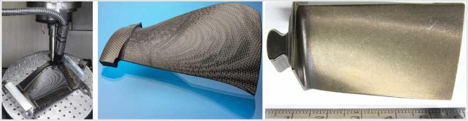
Fig. 1. CNC machining of a fiber-reinforced turbine blade, the machined part (Fraunhofer IPT, 2025) and a similar blade from an enterprise
As noted above, numerical micro modeling of composite structure and chip formation modeling of machining using edge tools is a practical necessity in the daily developments of industrial engineers. Such modeling makes it possible to predict the quality of the machined surface and develop technics to improve it, based on the choice of geometric parameters of the tool cutting wedge, tool kinematics in the workpiece coordinate system, cutting mode and other processing conditions. In such studies, micro modeling is necessary, since the surface fluffiness, various delaminations and chips can be detected by modeling of the workpiece considering material fibers. When discussing this problem, we should also note the level of computer equipment, which industrial engineers use. Using of expensive supercomputing technologies in ordinary practice cannot be considered a practical solution. In this regard, there is a need to develop models of composites that, on the one hand, make it possible to describe significant structure components: fibers, matrix and boundary layer, and on the other hand, to generate meshes with not more than 105 finite elements or SPH particles for nonlinear dynamic analysis. In addition, the modeling should be universal and enable one to generate both finite element meshes and simultaneously multiple SPH particles.
Therefore, the aim of the presented study is to develop a numerical geometric and physical model of a complex-shaped workpiece made of 3D woven fiber-reinforced composite and a finite element model of chip formation during edge tool machining for everyday use of industrial engineers.
1. Numerical geometric modeling of parts made of 3D woven fiber-reinforced composite
Since 3D woven FRCM with orthogonal arrangement of fibers includes fibers located in three directions, it is obvious to describe the axes of these fibers as spatial lines. If such lines are identical in shape, then it is sufficient to use one equation followed by replacing three coordinates according to the rule:
e *( n ) = F ( e *(n + 1) , e *(n + 2) ), n e {1, 2, 3} л n > 3: n ^ 1, (1)
where e (1) = x, e (2) = y, e *-3 = z - are the coordinates of the points on the lines.
The F function can describe a line of any spatial shape, including a straight line. This definition is necessary to model the orthogonal 3D structure of the FRCM. In the latter case:
e *( n ) = Ae *( n + 1) + Be *( n + 2) + D , (2) where A and B characterize angles of fiber inclination, and D describes the position of fiber in the selected coordinate system. In case if the fiber axes are parallel to the coordinate axes, it is enough to determine the coordinates of the points of intersection of the fiber axes with the coordinate planes: 1) xoy , 2) yoz , 3) xoz following simplified dependences
( x p ,1 = i -A x , У р ,1 = j -A y )л p = i + j • nm + 1 Л i , j = 0... nm — 1;
( Ур,2 = (j + 0,5) -AУ , zp,2 = i -Az ) Л P = i + j • nm + 1Л i = 0-nx - 1Л j = °-ny - 2; (3) ( xp ,3 = (j + 0,5)-Ax , zp ,3 =(i+ 0,5)-Az )Л P = i + j • Пт - 1Л i, j = 0... Пт - 2, where Ax, Ay, Az - are the distances between adjacent fibers in one row; nx, Пу, nz - are the numbers of fibers along the x, y, z axes, determined by dividing the overall dimensions of the part by the distance between the fibers; nm = max{nx, ny, nz} – is the maximum value.
In case if a fiber in radial cross-section is described as an ellipse, then it is sufficient to use a traditional ellipse equation. In a particular case, a fiber can be described as a cylinder using the equation of fiber cross section:
(
n
)-£(
n
) 2 + M
n
+
1)-E(
n
+
1)
2
( em E m ) + ( em + 1 E m + 1 ) - R , (4) where E mn ) - are the circle center coordinates calculated according to equation (2): E mn ) = em ( n ) , e (1) = x , e (2) = у , e (3) = z - are the current coordinates of voxel nodal points, R - is the fiber radius.
To describe a ring-shaped boundary layer, it is sufficient to use the dependence (4), and it is obvious that the expression on the left must be greater than the square of the fiber radius, but less than or equal to the square of the cylinder radius of this boundary layer.
Using dependencies (1)–(4), one can obtain a spatial mesh of cylinders, which describe orthogonally located fibers and their boundary layers. Next, using this mesh, the sets of voxels with the definition of their state parameters can be calculated: P ( x , у , z ) = 1 for the fiber and P ( x , у , z ) = 2 for the boundary layer.
To obtain a set of matrix voxels, the following relationship can be applied:
V P ( x , у , z ), P ( x , у , z ) = 3 - ( P ( x , у , z ) = 1 v P ( x , у , z ) = 2). (5)
The described dependencies (1)–(5) make it possible to calculate the voxel mesh of the composite workpiece in the form of a rectangular parallelepiped. To generate the similar mesh for a part of arbitrary shape, it is necessary to use the dependencies given in our previously published studies [14] and Bulletin of the South Ural State University. Ser. Mechanical Engineering Industry. 2022, vol. 22, no. 4. In this case, the specified voxel state parameter should be determined using the dependencies (5), if this parameter is non-zero in calculations for the entire part according to the dependencies presented in the mentioned study [14]. The obtained voxel models are further transformed into finite element models. The results of modeling of the earlier described turbine blade are shown in Fig. 2 (for clarity, the dimensions of the fibers and the boundary layers are increased by an order of magnitude). The total number of finite elements is equal to 382 590. This number is relatively large and indicates the limitations of the proposed approach: it is applicable only for small parts. To calculate deformations in large-sized parts, it is advisable to use macro modeling with an equivalent homogeneous structure.
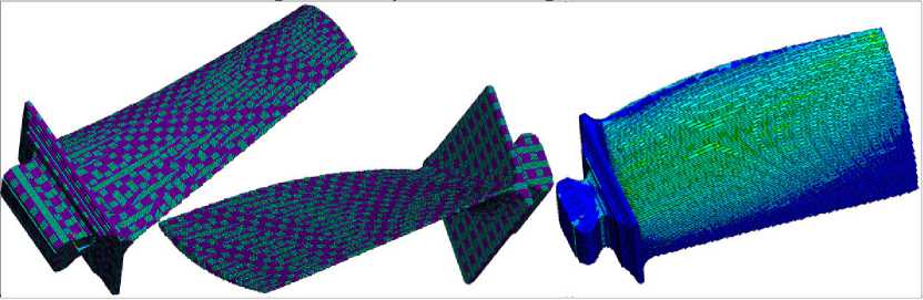
Fig. 2. Finite element model of the fiber-reinforced turbine blade and calculation of von Mises stresses caused by the cutting force applied at the tip of the blade
Механика
2. Numerical simulation of the stress-strain state of the 3D woven composite workpiece during the machining process
The above dependencies, which make it possible to calculate a set of voxel nodes, are the basis for the subsequent calculation of the finite element model nodes and elements or for the SPH model particles. To simulate the chip formation process, it is necessary to calculate cutting tool finite element model, determine friction coefficients, workpiece parameters, and tool motions. Recently, complex material models, such as the Johnson–Cook model [15], are increasingly used to study high-speed processes of interaction of the bodies considering their destruction. However, this simulation requires much more computation time compared, for example, with simulation using the Plastic Kinematic model [15] and borrowed parameters.
To calculate the cutting force by modeling the stress-strain state of the workpiece during machining, a rectangular parallelepiped fragment of the workpiece at some check point on its surface was selected. The geometric parameters of the fragment were as follows: fiber diameter 48 μm, boundary layer thickness 8 μm, distance between fiber axes 128 μm. The cubic workpiece had a size of 336 μm. The cutting tool had the following geometric parameters: tool rake angle and tool clearance angle were equal to 100 each. Rounded cutting edge radius was 20 μm. The simulation described tool face area, which was 160 µm long and tool flank area, which was 80 µm long. Free orthogonal cutting was simulated. The workpiece was fixed along the underside of the cube and along the cube back side away from the cutter tool. The generated finite element models are shown in Fig. 3. From left to right the model of fibers, the model of boundary layers, the model of the matrix and the resulting model of the workpiece with the cutting tool are presented.
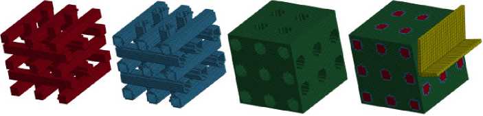
Fig. 3. Finite elements of composite workpiece structural components, complete workpiece model and cutting tool model
Von Mises stress distribution and relative deformations in the workpiece for the same conditions are presented in Fig. 4. For clarity, the image of the tool is not shown. The top row shows the stresses in the workpiece, fibers and boundary layers that arose almost at the initial moment of cutting. The middle row shows similar results for the middle tool location: stresses in the workpiece, fibers and boundary layers. On the right, directly the stresses in the composite fibers are shown. The bottom row shows tool location at the completion of the cutting process (in practical calculations this tool location is not used, it is shown to confirm modeling adequacy). The entire composite structure is shown on the left, composite fibers with the boundary layer are shown on the right. The results of full-scale experiments obtained in machining fiber-reinforced composites with tool wedges are shown below (Fig. 4, i , j [16] and k ) [5]. As shown in the figures, there is a qualitative similarity in the obtained surfaces, which indicates the adequacy of the modeling described above.
Thus, the chip formation modeling demonstrated, firstly, the adequacy of the proposed mathematical dependencies (1)–(5), which provide description of fiber-reinforced composite structures of a body of complex arbitrary shape, namely, an orthogonal 3D woven structure, to generate a high-quality finite element mesh. Secondly, the adequacy of the approach itself for modeling fibers, boundary layers, and matrix is confirmed by comparing the results of the presented modeling with the results of full-scale experiments.
3. Results and discussion
The obtained mathematical relationships and computer programs created on their basis made it possible to obtain numerical geometric micro models of parts made of three-dimensional fiber-reinforced composites using available CAD models of these parts. On this basis, the cutting process of a fragment of such a workpiece was simulated in its selected critical area, the stress-strain state of the workpiece and the resulting cutting force were calculated. Considering forces and clamping conditions, the defor- mations and bending of the entire workpiece were calculated. Then this bending can be used as corrector for the control program of the CNC machine, thereby increasing the processing accuracy. This modeling, as one might expect, is limited by the capabilities of modern personal computers available to industrial engineers. In this regard, this micro modeling is currently available for the analysis of relatively small parts. A number of issues in the mechanics of the cutting process also require clarification: the properties of the boundary layers of composite fibers, the values of the friction coefficients and the parameters of the fiber and matrix material models. It is necessary to clarify the tool models in view of the surface roughness and wear. All this is the basis for further increasing the adequacy of modeling and the accuracy of calculations. Nevertheless, the results obtained already now make it possible to increase the accuracy of calculations significantly compared to the analytical calculations widely used at present.
_. __ Ле»»«и«гич 0ММ Пни I»*
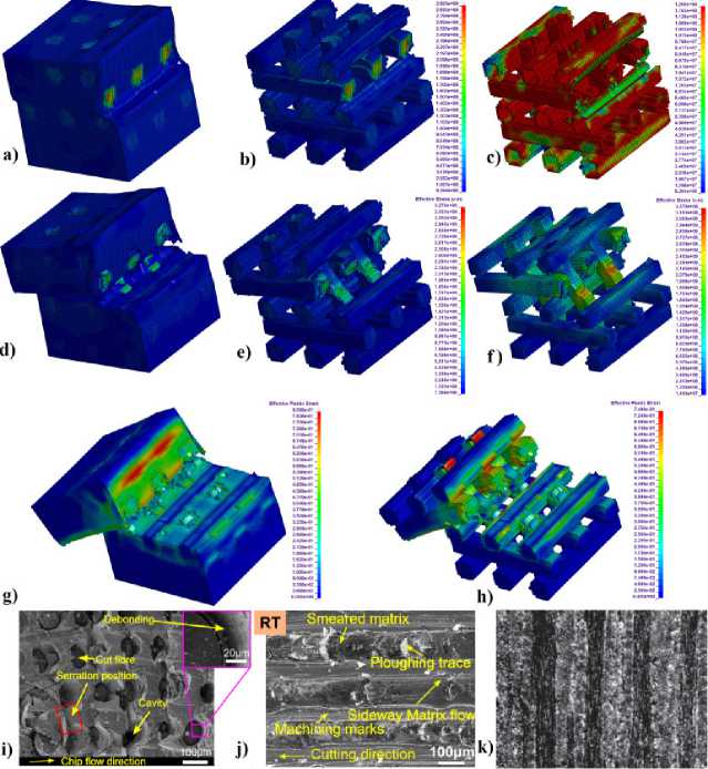
Fig. 4. Three stages of the cutting process. Von Mises stresses at the following tool locations: cut extends over 1/3 of the length of the workpiece: a) the complete workpiece, b) fibers with boundary layers, c) the boundary layer; similarly for 1/2 of the length of the workpiece: d), e), f); relative deformations at the tool location at 2/3 of the length of the workpiece: g) the complete workpiece and h) fibers with the boundary layers.
Results of full-scale experiments i), j) – [16], k) – [5]
Conclusions
The modeling of the 3D woven fiber-reinforced composite structure and the simulation of the chip formation process using edge tool performed by the authors leads to the following conclusions.
-
1. Micro modeling of small fiber-reinforced parts including a description of the fibers and their boundary layers, that is the generation of voxel and finite element models using existing personal computers is practically achievable.
-
2. Predicting the accuracy of the composite part during CNC machining can be achieved through its micro modeling in view of fibers and boundary layers, calculating the stress-strain state in the cutting zone and calculating displacements in the entire workpiece caused by the cutting forces.
Acknowledgement. This work was supported by the Russian Science Foundation under grant no. № 24-71-00071,
Механика
