CRPCG—Clustering Routing Protocol based on Connected Graph

Author: Feng Li, Liuhong Huang
Journal: International Journal of Intelligent Systems and Applications(IJISA) @ijisa
Article in issue: 3 vol.3, 2011.
Free access
In order to balance the load between cluster head, save the energy consumption of the inter-cluster routing, enhance reliability and flexibility of data transmission, the paper proposes a new clustering routing protocol based on connected graph (CRPCG). The protocol optimizes and innovates in three aspects: cluster head election, clusters formation and clusters routing. Eventually, a connected graph is constituted by the based station and all cluster heads, using the excellent algorithm of the graph theory, to guarantee the network connectivity and reliability, improve the link quality, balance node energy and prolong the network life cycle. The results of simulation show that, the protocol significantly prolong the network life cycle, balance the energy of network nodes, especially in the phase of inter-cluster data transmission, improving the reliability and efficiency of data transmission.
Connected graph, multiple paths, optimal tree, Leach, clustering routing
Short address: https://sciup.org/15010173
IDR: 15010173
Text of the scientific article CRPCG—Clustering Routing Protocol based on Connected Graph
Published Online May 2011 in MECS
As the rapid development of microelectronics technology, low-power embedded technology, wireless communication technology and distributed information processing technology, wireless sensor network (WSN) has become a hotspot of modern science and technology, known as the third technological revolution [1]. WSN has the following characteristics: limited node power, wireless self-organizing network, and low-power deployment, data-centric and application relevance. Therefore, according to different application requirements, development of appropriate communication protocol has become a research focus and difficulty. WSN's routing protocols can be divided into flat and hierarchical routing protocols, and clustering routing protocol based on hierarchical topology has become a research hotspot [2].
This paper analyzes the LEACH protocol [3] and clustering routing protocols based on tree structure, fully absorb its advantages, optimize and innovate structural deficiencies, fundamentally change the inter-cluster network topology and resolve the problems encountered by innovative thinking. The paper presents a clustering routing protocol based on connected graph protocol (CRPCG). The based station and all the cluster head forms a connected graph structure, rather than the tree structure, so as to better balance the network load, improve network reliability and prolong the network life cycle.
-
II. Classic Clustering Routing Protocol
Clustering routing protocol is typical representative of hierarchical routing protocols. Compare with flat routing protocol, according to some factor network nodes are divided into different sets named by "cluster" for clustering routing protocol. The cluster is composed of a cluster head and some member nodes, the cluster head is elected in accordance with some rule, non cluster-head node (member node) join into a cluster according to some rule, and ultimately forming tertiary hierarchy structure includes member node, the cluster head and the base station. Here we emphatically analyze the LEACH protocol and clustering routing protocols of tree structure based on LEACH.
A. Leach Protocol
Low-Energy Adaptive Clustering Hierarchy (LEACH) [3] is one of the most classical hierarchical routing algorithms for sensors networks, which was proposed by Chandrakasan, etc. The idea is to elect cluster-heads randomly and equal probability without the base station processing, and other sensor nodes based on the received signal strength join into a cluster and use local clusterheads as routers to the base station. All the data processing such as data fusion and aggregation are local to the cluster-head. Cluster-head change randomly over time in order to balance the energy consumption of nodes. This decision is made by the node choosing a random number between 0 and 1. The node becomes a cluster head for the current round if the number is less than the following threshold:
P if n e G otherwise
T ( n ) = <
1 - P x [ r mod ( 1/ P ) ]
Where P is the desired percentage of cluster heads (e.g. 0.05), r is the current round, and G is the set of nodes that have not been cluster heads in the last 1/P rounds.
In order to save resource overhead, the duration of data transmission should be longer than the establishment phase for the Leach protocol. Compare with the flat routing protocols, the Leach protocol greatly extend the network lifetime. But there are some problems [4-5]: (1) Due to the cluster head for single-hop send data to the base station, while the node communication range is limited, so it is not suitable for large scale wireless sensor network applications; (2) Because the cluster head is Random elected, it may cause uneven distribution for the cluster head, and appear some blind spots. There is a great gap between the size of the cluster, and the energy consumption of cluster head is unbalanced, causing rapid death of some cluster heads; (3) In the cluster head election phase, it does not consider other factors, such as: residual energy, number of neighbor nodes, node density, distance to the base station, etc. In the joined into the cluster phase, it only considers the signal strength, but without considering other factors.
B. Improved Protocol Based on Tree Structure
As some deficiencies of the LEACH protocol, researchers present some improved protocol based on LEACH [6], which enhance and optimize in three following stages: (1) for cluster head election, mainly adding node residual energy and other factors into consideration [7]; (2) for formation of cluster, adding the cluster head residual energy and current scale of the cluster [8]. But in the inter-cluster routing phase, these improved protocols are to form tree structure with the base station as the root, and with all cluster-heads as the branch or leaf node [9]. Data transmission is routed by way of tree routing: the cluster heads to collect data, transmit them layer-by-layer upward along with established branches, and eventually reach the base station [8, 10], as shown in Fig.1.
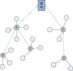
Figure 1. Tree topology structure based on LEACH
Tree routing improved protocol overcomes partly the shortage of the LEACH protocol, but raises some new problems due to the defects of tree structure itself, as follows [11-13]:
-
(1) Once tree structure is formed completely, data transmission paths are confirmed between all cluster heads and the base station, and hardly changes in this round.
-
(2) As undertaking more data transmission tasks from sub-tree, cluster heads near to the base station will consume more energy than others far from the base station.
-
(3) In the tree structure, a branch cluster head failure will lead to all of its following sub-tree cannot work well, and form chain scission.
-
(4) When a cluster head has too many sub-trees and send data frequently, this will increase the burden of the cluster head and result in excessive energy consumption of this branch.
-
(5) If it need to transmit data between the different cluster head, but needed by the base station, which leads to additional energy waste.
-
III. The CRPCG Protocol
The CRPCG protocol fully takes into account defects of the Leach and tree-structure protocols based on the Leach, and its main idea is: In the cluster head election phase, at first, the candidate cluster head is selected based on residual energy, and then according to the cluster size scale and cluster communication cost to determine the final cluster head. In the joining into the cluster phase, non cluster-head nodes are divided into three categories, which select the cluster to join according to the corresponding threshold, to better save the node energy sent data to the cluster head and balance the size of the cluster. After all the cluster formed, all cluster heads and the base station forms a connected graph according to some rules, with the breadth first search (BFS) algorithm in graph theory, considered the base station as the source, we can calculate the optimal path for all cluster heads that along this path to transfer data to the base station is the smallest energy consumption and delay. In the data transmission phase, as the connectivity between the cluster head, there are multiple paths between the base station and cluster head, based on the actual application, according to the different trade-offs we can select the right path, and reflect the application relevance of wireless sensor network.
A. Energy Dissipation Model
The CRPCG protocol adopts the same energy model -first order radio transmission model [14] with the LEACH protocol. E Tx represents the energy consumption of transmitting data, which is made up of the energy needed to start the transceiver ( E Tx-elec ) and the energy needed to transmit data ( E Tx-amp ), it defines in formula (2). E Rx represents the energy consumption of receiving data, which only depends on the data size, and it defines formula (3). Thus, to transmit a k-bit message a distance d , the radio expends
E tx ( k , d ) = E tx - elec ( k ) + E tx _ amp ( k , d )
kEelec + k • emP • d 4 , d >= d 0
And to receive this message, the radio expends
E Rx (k)=E Rx-elec (k)=kE elec (3)
For the radio hardware energy dissipation model, the energy consumption of the wireless signal transmission increases with distance more extremely. Both the free space (d2 power loss) and the multipath fading (d4 power loss) channel models are used, depending on the distance between the transmitter and receiver. If the distance is less than a threshold, the free space model is used; otherwise, the multipath model is used [15].
Given the above discussion, we show that the energy consumption is mainly from the radio transmission model, the energy consumption increases with the distance. In the CRPCG protocol, we take full advantage of the energy consumption sent data and threshold d o , as soon as possible we reduce transmitted distance ( d is less than d o ) whether data transmission of inter-cluster or intracluster, and thus significantly reduce the energy consumption of data transmission.
B. Formation of Cluster
Cluster head election is the basis of cluster formation, which considers three factors: residual energy of each node, the number of neighbor nodes and the average distance from the node to all its neighbor nodes. Cluster head election depends on primary and secondary parameters. The primary clustering parameter is based on the residual energy of each node, and to select the candidate cluster head. The secondary parameter is based on a Value(n,e) function to confirm the final cluster head, where n representing of the node density is the number of neighbor nodes of a candidate cluster head, and e representing of intra-cluster communication cost is the average distance from candidate cluster head to all its neighbor nodes. And, Value function is bigger; the more likely candidate cluster head becomes final cluster head. Finally, cluster member nodes join into the cluster.
1) Selecting Candidate Cluster Head
In the Leach protocol, selecting cluster head is a random decision based on whether the node was selected previously, and without taking into account the residual energy of nodes. After several rounds, it is possible that more residual energy node elected cluster head probability is small, but less residual energy node elected cluster head probability is large, resulting in energy imbalance.
Based on the deficiency of the Leach protocol, we take into account residual energy of the node in the cluster head election phase. The larger residual energy has a greater probability to become candidate cluster head; otherwise, the probability is smaller. For the CRPCG protocol candidate cluster head is elected according to the formula (4) and formula (5), as follows:
T CRPCG (n)
T(n) x (
Residual Energy Average Energy
)
if n e G
otherwise
p
= ^ 1-p x [mod—] P
E ft)
X current( У
E aveEn
if n e G
_ 0
otherwise
Where E current(i) represents the residual energy of the node i when it runs for the cluster head; E aveEn is the average energy of all the surviving nodes currently in the network; E current(i) / E aveEn represents that the nodes with more residual energy in the campaign candidate cluster head has a greater probability, low probability and vice versa. E aveEn
is calculated as follows: when the network first is started, EaveEn is the average initial energy. After that, all member nodes send their residual energy to the cluster head at the end of each round, cluster head is responsible for statistics of average residual energy of this cluster. Once completed, all cluster heads send the average energy of the cluster and the number of the member node to the base station. The base station calculates the current average energy of all the surviving nodes, and embeds into a new round of network reconfiguration command to inform of all the network nodes.
-
2) Confirming Final Cluster Head
Once a node is elected as a candidate cluster node, it begins to calculate
Value
function according to the number of its neighbor node and distance from all the neighbor nodes to it, see formula (6). The criteria for determining neighbor nodes depends on the cluster radius
R
, in the circle of radius
R
covered nodes is the number of neighbor nodes, so the election quality for
R
will directly affect the cluster head election. The choice of
R
depends on the size of the region and the threshold
d
o
of the radio energy dissipation model, and usually determine
R
Value ( i ) = ax ( P x S ( i ) nbSze ) + (1 - a ) x ( R ) (6) S ( i ) aveDist
Where, S(i)nbSize is the number of the candidate cluster head i (representing the node density). S(i) aveDist is the average distance of all its neighbors to the candidate cluster head i (representing the intra-cluster communication cost). And a is the weighting coefficient, which can dynamically balance the node density and the intra-cluster communication cost. R is the cluster radius; P is the percentage of the node elected as cluster head. Based on the formula (6), when a candidate neighbor node has more neighbors (that is, S(i) nbSize is larger), or the average distance is smaller (that is, S(i) aveDist is smaller ), the Value function will be larger, otherwise smaller..
When a candidate cluster head calculates the value of it Value function, it begins to broadcast Value in the cluster radius R . The other candidate cluster heads receive the broadcast, and which have been stored the candidate identity ID with larger Value , but the ordinary nodes ignore the broadcast. After some time, until all candidate cluster heads have broadcast their own Value , if the stored largest candidate cluster head is itself, it becomes the final cluster head, otherwise ordinary node. We can ensure that the distance is greater than the radius R between any two final cluster heads, so that final cluster head distribution is more uniform and reasonable, and energy consumption of each cluster of each round is uniformly shared.
-
3) Joining into Cluster
After the final cluster head is elected, it begins to broadcast its message elected final cluster head in the radius q*d o , the message includes the identity ID and the Value of it. Where, d o is the threshold of the radio energy dissipation model; q adjusted the broadcast radius of the cluster head is a broadcast coefficient, which is used for the ordinary nodes joining into the cluster and constituting a connected graph. So the value of q is critical directly to
determine the number of the isolated nodes (not a member of any cluster) and density of connected graph formed. When q = 1 , the CRPCG protocol has a better performance, because we can limit energy consumption of inter-cluster and intra-cluster data transmission to d2 instead of d4 , and thus significant savings in energy consumption of data transmission.
When the ordinary node receives the broadcast message sent the final cluster head, according to the distance with the cluster head, joining into a final cluster head is divided into three cases, such as formula (7), where d is the distance between this node and final cluster head, R is the cluster radius, d o is threshold of the radio energy dissipation model.
d < R , join cluster head with smallest Value;
< R < d < d o , join cluster head with smallest size;
d > d o , join cluster head with smallest distance.
These three cases have the following order of priority:
First, if there is a cluster head that the distance d with this ordinary node is less than the cluster radius R , no longer considering the second and third case. This ordinary node joins into the cluster head with the smallest Value . " d < R " shows that the distance d is less than the threshold d o of radio energy dissipation model, energy consumption of data transmission is proportional to d2 , and the distance impact on energy consumption is smaller, we preferentially considers the size scale of the cluster. Joining into the cluster head with the smallest Value can balance the size scale of the cluster, the cluster scale is the same as soon as possible so that closer gap between the clusters that are using the energy balance.
Second, if there is no a cluster head that the distance d is less than the radius R , but there is a cluster head that the distance d is greater than the radius R , but less than the threshold d o , no longer considering the third case. This ordinary node joins into the cluster head with the smallest cluster size. " R < d < d o " shows that the distance d is less than the threshold d o , energy consumption of data transmission is proportional to d2 , and the distance impact on energy consumption is smaller, we further considers to balance the size of the cluster.
Third, if the distance d between all the cluster heads and this ordinary node is greater than the threshold d o , This ordinary node joins into the cluster head with the smallest distance d . " d >= d o " shows that the distance d is equal and greater than the threshold d o , energy consumption of data transmission is proportional to d4 , and the distance impact on energy consumption is bigger, we should first consider the distance d factor. Joining into the cluster head with the smallest distance would be better to save the network node energy. The node of this case is very small, and mostly occurred in having many dead nodes in network, does not have a great impact on the size of the cluster.
C. Structure Between The Cluster Head
All final cluster head nodes do not form the tree structure, but the connected graph. Each cluster head including the base station possesses an upper neighbor list and a lower neighbor list. Each element of the upper neighbor list is a five-tuples U(ID, Enode, EBS, Tdelay, N), while it is a two-tuples U(ID, Enode) for the lower neighbor list. Edge relations of the connected graph are represented and maintained through the upper and lower neighbor list, and ultimately to form a connected graph G(V, E) that the base station (source node) and all the cluster heads are as the node set V, and the edge relations between the upper and lower neighbor lists are as the edge set E.
-
1) Forming Connected Graph
When the final cluster head broadcasts the message elected the cluster head, the other cluster head receives this message and uses the following rules to determine whether forming a link road to the cluster head. Constructing a connected graph and including the following three aspects:
-
(1) The base station and cluster heads. Link path is formed between the base station and cluster heads away from the base station within distance q*d o . And the base station is added to the upper neighbor list of these cluster heads, these cluster heads are added to the lower neighbor list of the base station. If none of cluster head is less than q*d o (this case only happens when many nodes die in network), the base station is connected with the nearest cluster head away from the base station.
-
(2) Between the cluster head. Whether cluster head i and cluster head j form a link path or not depends on two factors: the distance between them and their distances to the base station. Once the cluster head i and j form a link path, they are added to their corresponding upper and lower neighbor list. If the distance between the cluster head i and j is equal and greater than (q+yd/ym)*d o , do not form a link path; otherwise, according to the following formulas (8) to determine whether to form a link path. Where yd represents the smaller vertical distance between cluster head i / j and the base station; ym represents the furthest vertical distance from the base station in the entire network region.
S(i).yd < S(j).yd - R S(j).yd+R J S (i). yd - S (j). yd| < R i join upper list of j i join lower list of j do not create link
Where, R is the cluster radius; S(i).yd or S(j).yd represent the vertical distance between the base station the cluster head i or j . Choice of (q+yd/ym)*d o and R directly impact on density level of the connected graph. The above formula guarantees that a link path is only formed when the distance between the cluster head is greater than R . That assures effectiveness and efficiency of the link path and prevents data from being transmitted and forwarded with less efficient in the network. " yd/ym ” ensures that cluster heads closer to the base station form the dense link paths. Because these cluster heads need to take on more forward tasks than others, the more intense link paths are the more selection for transferring data, and be better to balance and offset more energy consumption for these cluster heads closer to the base station.
-
(3) Isolated cluster head or isolated sub-graph. After finished above (1) and (2), For the cluster head with its upper neighbor list being empty, it indicates that it can not reach the base station, then it will be connected with the cluster head as upper that is the closest to the base station and also the shortest to the isolated cluster head; if not, it directly connects the base station. The closest to the base station ensures the data is forwarded to the cluster head closer to the base station, and the shortest to the isolated cluster head ensures that the energy consumption of forwarding to the cluster head is as small as possible.
The connected graph is constructed by the above three steps, all the cluster heads and the base station are connected through link paths, shown in Fig.2:
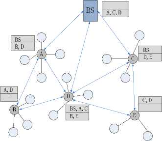
Figure 2. The connected graph topology structure of CRPCG
-
2) Creating Cluster Path
After all the cluster heads and the base station constitute a connected graph in the CRPCG protocol, each cluster head has multiple paths to reach to the base station. In this section we describe a method of constructing minimum energy consumption paths, so that it is the minimum and optimal path for energy consumption among all the paths reaching to the base station, and be known as the "optimal tree" of the connected graph.
For the connected graph formed by all cluster heads and the base station, we consider the base station as the source point, perform the Breadth First Search ( BFS ) of graph theory, and calculate E BS and T delay of the element in the upper neighbor list for all cluster heads layer by layer. Here we take E BS as the measure (For time-sensitive network we can take T delay as the measure). During performing the BFS algorithm process, since each cluster head (including the base station) has a lower neighbor list to identify its all direct lower cluster heads, so you can traverse all cluster heads. In the implementation of BFS , if the lower neighbor list of a cluster head is empty, this path has finished and the cluster head is a leaf node for the constructed optimal tree.
In the process of executing BFS algorithm, when calculating the cluster head i, we choose the element having smallest EBS in its all upper neighbor lists as its optimal upper cluster head, that is, energy consumption is the smallest through the optimal upper cluster head to transmit data to the base station. For example, for the direct lower cluster head j of the cluster head i, we perform the following rule. If the sum of EBS of optimal upper of cluster head i and direct energy consumption between i and j is less than EBS of current optimal upper of cluster head j, cluster head i is set as the optimal upper cluster head of cluster head j, and update EBS of the upper cluster head i of cluster head j; otherwise, only updating EBS, do not set the optimal upper cluster head.
When the BFS algorithm is completed, an optimal tree is constructed with the base station as the root and all cluster heads as branches or leaves, shown in Fig.3, in which the red mark is the optimal upper cluster head, the red side is the optimal tree with cluster path.
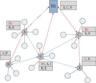
Figure 3. The optimal tree of the connected graph of CRPCG
D. Data Transmission
The CRPCG protocol is the same as other clustering routing protocols, data transmission is divided into intracluster and inter-cluster data transmission. The two kinds are described in detail as follows:
First, intra-cluster data transmission. The CRPCG protocol is the same as the Leach protocol; there is only one-hop distance between the cluster member node and cluster head. The cluster head distributes the Time Division Multiple Address (TDMA) time slots for all member nodes of the cluster. Each member node sends data to the cluster head in its own time slot, for other times it can turn off its wireless communication module, to save energy. The cluster head is responsible for collecting and integrating all data of the cluster to send to the base station.
Second, the inter-cluster data. Since the CRPCG protocol constitutes a connected graph between the cluster head and the base station, inter-cluster data transmission is different from other clustering routing protocols, and has its own unique way. There are multiple paths from each cluster head to the base station for the connected graph, so several paths are selected. Based on the actual application, each cluster head send data to the base station according to five-tuples U(ID, E node , E BS , T delay , N) of its upper neighbor lists, and choosing the right combination depends on four factors: residual energy of its upper cluster head ( E node ), minimum energy consumption through its upper cluster head to the base station ( E BS ), minimum time delay through its upper cluster head to the base station ( T delay ), link load of its upper cluster head( N ), etc. We introduce the two following inter-cluster data transmission scheme:
-
(1) The first scenario: the optimal tree. All cluster heads transmit data to the base station through their optimal upper cluster head, so that all inter-cluster data is transmitted to the base station along with the optimal tree, then inter-cluster energy consumption of data transmission is minimum.
-
(2) The second scenario: we synthetically consider the residual energy ( Enode ) and minimum energy consumption reaching to the base station ( E BS ) both. When each cluster head transmits data, it calculates TranV function of each its upper cluster head, and forwards to the upper cluster head with the maximum value of TranV function, until the base station. TranV function is calculated as follows formula (9):
TranV ( i ) = 5 x ( -Ei- ) + (1 - 5 ) x ( A- ) (9) E aveEn E BS
Where, s is the weighting coefficient, which can dynamically balance the node residual energy and minimum energy consumption to the base station; E(i) is the current residual energy of upper cluster head i ; E aveEn is the average energy of all the surviving nodes in the network for current round; do is the threshold of the radio energy dissipation model; E BS is minimum energy consumption from upper cluster head i to the base station (here we use the distance to replace).
Given the above discussion, we found that the maximum advantage of connected graph is more choice and more multiple paths reaching the base station when transmitting data in inter-cluster. Thereby that improves reliability, flexibility and application-related of intercluster data transmission. Based on E node , we can balance the residual energy of cluster heads, and to prevent the rapid death of the local cluster head. Based on E BS , we can minimize energy consumption of inter-cluster data transmission, and to save energy. Based on T delay , we can improve the timeliness of data transmission, and to reduce data time delay. Based on N , we can balance the load on the link path, and to prevent data transmission from blocking. Through U(ID, Eno d e, EB S , T d e l ay, N) , we can significantly overcome deficiencies of the LEACH protocol and improved protocol based on tree structure.
E. Data Update
Since each cluster head (including the base station) possesses its own upper and lower neighbor lists, cluster heads transmitted data need to regularly update its residual energy ( E node ) and link load ( N ) of upper and lower neighbor lists in other cluster heads.
The CRPCG protocol uses "round" as the time identification, each round contains several frames. After one frame is completed, all cluster heads which sent or forwarded data need to transmit their current residual energy and their sent data quantity in current frame to each cluster head in their lower neighbor lists, and to update relevant elements in upper neighbor lists of their lower cluster head. At the same time, they transmit their current residual energy to each cluster head in their upper neighbor lists, and to update relevant elements in lower neighbor lists of their upper cluster head. At the end of the round, the base station collects and calculates average energy of all the surviving nodes in this round, and embeds in constructed message of next round to inform of all surviving nodes.
-
IV. Simulation and Anlysis
In this paper, we use MATLAB simulation to simulate the CRPCG and Leach protocols respectively. In the simulation, various parameters and thresholds are shown in Table I:
Table I: Value of simulation parameters
|
Parameters |
Value |
|
Sensing area ( M ) |
500m*500m |
|
Position of Base Station ( M ) |
(250, 500) |
|
Number of sensor nodes ( N ) |
200 |
|
Percentage of candidate cluster head ( P ) |
20% |
|
Cluster radius ( R ) |
50 m |
|
Initial node energy level ( E init ) |
0.5J |
|
Frames of one round |
10 |
|
Coefficient of formula.6 ( a ) |
0.5 |
|
Broadcast coefficient ( q ) |
1.5 |
|
Coefficient of formula.9 ( s ) |
0.5 |
|
Threshold distance ( d o ) |
87m |
|
RF Radio circuitry energy ( E elect ) |
50 nJ/bit |
|
Amplifier energy for Free space loss ( εfs ) |
0.0013 pJ/bit/m4 |
|
Amplifier energy for Multipath loss ( εmp ) |
10 pJ/bit/m2 |
Based on the above parameter settings in the simulation, we run the CRPCG protocol and the Leach protocol. We compare the simulation results of both protocols in the following four aspects in detail, and analyze the significance of the results.
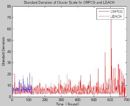
Figure 4. The standard deviation of the cluster scale
Fig.4 shows standard deviation of cluster scale for the CRPCG and LEACH protocol. Looking at the graph of
Fig.4, standard deviation of the CRPCG protocol is much smaller than the Leach protocol, and for the CRPCG protocol fluctuation of the standard deviation is relatively small. This shows that the CRPCG protocol has a more even cluster scale, and the discrete degree of cluster scale is smaller in each round. At the same time, the proximity of cluster scale is no major changes, and reflects its stability.
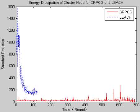
Figure 5. The standard deviation of energy consumption of cluster head
Fig.5 shows standard deviation of energy consumption of the cluster head for the CRPCG and LEACH protocol, and reflects gaps in energy consumption of all cluster heads in each round; we can see whether the energy consumption of cluster head is balanced. Looking at the graph of Fig.5, standard deviation of the CRPCG protocol is much smaller than the Leach protocol, and for the CRPCG protocol fluctuation of the standard deviation is relatively small. This shows that the CRPCG protocol in each round has a more balanced and stable energy consumption of cluster head, thereby ensuring there is no phenomenon that some local cluster heads rapidly die because of excessive energy consumption.
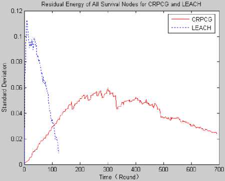
Figure 6. The standard deviation of residual energy of all survival nodes
Fig.6 shows standard deviation of residual energy of all survival nodes in the network for the CRPCG and LEACH protocol, and reflects gaps in energy consumption of all survival nodes. Looking at the graph of Fig.6, standard deviation of the CRPCG protocol is much smaller than the Leach protocol. This shows that all sensor nodes in the CRPCG protocol have closer energy consumption and smaller gap, which reflects the energy consumption shared equally to each node as much as possible. So the CRPCG protocol can be better shared equally energy consumption for all survival nodes to avoid premature death, thus prolonging the network life cycle.
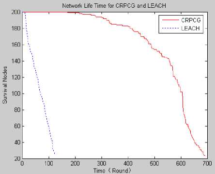
Figure 7. The network life cycle of two protocols
Fig.7 shows network life cycle of the CRPCG and LEACH protocol, here we use "round" to represent. Based on comparison, we found that the CRPCG protocol has a much longer network life cycle than the Leach protocol, which describes the CRPCG protocol has a huge optimization and innovation to prolong the network life cycle.
For the network life cycle that we take the first node killed, 10% of node death, 50% of node death, and 90% of node death (which means the failure of the entire network) as a standard to measure. We have repeatedly run the simulation experiment, and do statistics of the above four situation to calculate the average, the specific statistics are as follows:
Table II: Network life cycle of the two protocols
|
CRPCG |
LEACH |
|||||||
|
Kind |
1 |
10% |
50% |
90% |
1 |
10% |
50% |
90% |
|
Round |
170 |
407 |
606 |
692 |
8 |
17 |
68 |
123 |
|
Round |
106 |
357 |
639 |
752 |
11 |
15 |
61 |
122 |
|
Round |
226 |
368 |
613 |
768 |
8 |
16 |
63 |
121 |
|
Average |
167 |
377 |
619 |
737 |
9 |
16 |
64 |
122 |
Table II shows that for the network life cycle, in the same simulation circumstances, the network life cycle of the CRPCG protocol is ten times than the Leach protocol. Thus, the CRPCG protocol has been improved in all aspects, and can significantly prolong the network life cycle.
For the CRPCG protocol, greatly prolonging the network life cycle has some following reasons: (1) fully optimizing cluster head election, making a more uniform distribution of cluster heads, balanced scale and energy consumption of all cluster heads in each round, and effectively preventing occurring for premature local cluster head; (2) data transmission in inter-cluster, it is to transfer energy to maintain a level proportional to the square of distance, not the fourth power of distance, and save energy of the cluster head sent data to the base station; (3) when the data is sent to the base station, based on the connected graph we can select the multiple paths, and further balance the energy consumption of cluster head; (4) since we fully think over intra-cluster and intercluster data transmission, and better allocate energy consumption to each node in the network, and balance the energy consumption of all nodes.
-
V. Conclusion
In this paper, we first studied the Leach protocol and improved protocol based on the tree structure. we presents a clustering routing protocol based on connected graph protocol (CRPCG), which controls electing cluster head and ordinary nodes joining into the cluster based on residual energy, node density and intra-cluster communication cost, The based station and all the cluster head forms a connected graph structure rather than the tree structure, so as to have multiple paths reaching the base station for each cluster head in the inter-cluster data transmission. We still need to do further research for some shortcoming of the CRPCG protocol, including: when the cluster head is elected, it may run into a recursive path, and result in less cluster head nodes; When building a connected graph, it appears that a large sub-graph has only one path reaching the base station. Simulation results show that, the CRPCG protocol has a more even distribution of cluster head, and better balances the scale and load of all cluster heads, improves reliability and flexibility of data transmission, and significantly prolongs the network life cycle.
References CRPCG—Clustering Routing Protocol based on Connected Graph
- Akyildiz IF, Su W, Sankarasubramaniam Y, Cayirci E. A survey on sensor networks. IEEE Communications Magazine, 2002, 40(8): 102−114.
- Shen B, Zhang SY, Zhong YP. Cluster-Based routing protocols for wireless sensor networks. Journal of Software, 2006, 17(7):1588−1600.
- W.R. Heinzelman, A. Chandrakasan, H. Balakrishnan. Energy-effcient communication protocol for wireless micro sensor networks, IEEE Proceedings of the Hawaii International Conference on System Sciences, January 2000, pp. 1–10.
- SONG Chun-Yan, ZHANG Hua-zhong, ZHANG Xiu-yang. Clustering hierarchy tree routing algorithm based on LEACH. Journal of Computer Applications,2008-10
- Zhu Xiao rong, Shen Lian feng. RBF-based cluster-head selection for wireless sensor networks. Journal of Southeast University (English Edition) Vol.22, No.4, pp.451 - 455
- O. Younis, S. Fahmy, HEED: A Hybrid, Energy-Effcient, Distributed clustering approach for Ad Hoc sensor networks. IEEE Transactions on Mobile Computing 3 (4) (2004) 366–379.
- Handy MJ, Haase M, Timmermann D. Low energy adaptive clustering hierarchy with deterministic cluster-head selection. In: Proc. of the 4th IEEE Conf. on Mobile and Wireless Communications Networks. Stockholm: IEEE Communications Society, 2002.368−372.
- Ye M, Li CF, Chen GH, Wu J. EECS: An energy efficient clustering scheme in wireless sensor networks. IEEE Int’l Performance Computing and Communications Conf. IEEE Press, 2005.535−540.
- Manjeshwar A, Grawal DP. TEEN: A protocol for enhanced efficiency in wireless sensor networks[C]. In: Proc. of the 15th Parallel and Distributed Processing Symp. San Francisco: IEEE Computer Society, 2001. 2009−2015.
- O. Younis, S. Fahmy. HEED: A Hybrid, Energy-Efficient, Distributed Clustering Approach for Ad Hoc Sensor Networks[C]. Proceeding of IEEE INFOCOM, 2004:366-379.
- SHAH R C,RABAEY J. Energy aware routing for low energy Ad hoc sensor networks [C] .Proc of IEEE Wireless Communications and Networking Conference.2002:350-355
- Ye M, Li CF, Chen GH, Wu J. EECS: An energy efficient clustering scheme in wireless sensor networks[C]. In: Proc. of the IEEE Int’l Performance Computing and Communications Conf. New York: IEEE Press, 2005. 535−540.
- Younis M, Youssef M, Arisha K. Energy-Aware routing in cluster-based sensor networks[C]. In: Proc. of the 10th IEEE Int’l Symp. on Modeling, Analysis and Simulation of Computer and Telecommunications Systems. Fort Worth: IEEE Computer Society, 2002.
- W. B. Heinzelman, A .P. Chandrakasan, and H.Balakrishnan. An Application-Specific Protocol Architecture for Wireless Microsensor Networks[J]. IEEE Transactions on Wireless Communications, 2002.1(4):660-670.
- S. D. Muruganathan, D. C. F. Ma, R. I. Bhasin, and A. O. Fapojuwo. A Centralized Energy-efficient Routing Protocol for Wireless Sensor Networks [J]. IEEE Communications Magazine, 2005.43: 8-13.
