
Design development and experimental studies of chambers of low-thrust rocket engines with regenerative cooling
Journal: Siberian Aerospace Journal @vestnik-sibsau-en
Section: Aviation and spacecraft engineering
Article in issue: 2 vol.27, 2026.
Free access
The development and practical application of low-thrust rocket engines with enhanced reliability and functional performance characteristics is a promising scientific, technical, production and technological task in the creation of new-generation spacecraft and upper stages. In the process of implementing the Cooperation Agreement concluded by the State Scientific Center of the Russian Federation "M. V. Keldysh Research Center", the Siberian State University of Science and Technology named after M. F. Reshetnev, with the participation of Polychrome LLC, is conducting a complex of research and experimental work on the design, manufacture by additive 3D printing technologies and bench tests of prototypes of low-thrust rocket engines powered by gaseous fuels with a regenerative chamber cooling system. At this stage of the joint work, two small thrust engine chambers were selected as the object of research. These chambers were manufactured using the ASTRA 420 3D printer from the heat-resistant alloy Inconel 718 in the form of monoblock products with meridional (longitudinal) and helical (spiral) cooling channels. The thermodynamic and gas-dynamic calculations, as well as the calculation of the regenerative cooling of the chambers using methane gas, were performed using the results of experimental and analytical studies conducted by the Keldysh Research Center. The article describes the sequence of development and optimization of additive printing technology for cameras, which ensures the required product quality. The results of bench and experimental versions of two chambers with the same configuration of mixing heads and different channel orientations of the cooling system are presented in an expanded volume. When analyzing the energy and thermal parameters of the chambers obtained during fire tests, the operability of experimental designs was demonstrated, confirming the prospects of the selected technical solutions. The principal possibility of manufacturing low-thrust rocket engines using additive technology of selective laser melting from a heat-resistant alloy is shown.
Short address: https://sciup.org/148333981
IDS: 148333981 | UDC: 621.454 | DOI: 10.31772/2712-8970-2026-27-2-238-257
Text of the scientific article Design development and experimental studies of chambers of low-thrust rocket engines with regenerative cooling
In modern domestic and international astronautics, particular attention is given to the development and practical application of low-thrust propulsion systems. The use of unconventional propellant components, the development of high-lifetime and reliable multiple-start systems, and the implementation of advanced additive manufacturing technologies for producing complex integral structures create conditions for expanding the functional capabilities and operational range of low-thrust rocket engines [1, 2].
Among the relevant and promising scientific and technological challenges in the development of next-generation low-thrust rocket engines is the use of gaseous propellant components, such as hydrogen (H₂) and oxygen (O₂), or methane (CH₄) and oxygen (O₂), together with thermal protection of the combustion chamber provided by an external (regenerative) cooling system using a gaseous coolant. These complex challenges are most effectively addressed through the fabrication of a monolithic engine chamber with a finned cooling channel and a mixing head using 3D printing from heat-resistant powder materials. This technological approach enables a reduction in the final mass of the component by optimizing the design with regard to the distribution of mechanical loads across the internal elements of the gas flow path. At the same time, the application of additive manufacturing (3D printing) must include additional control of surface roughness and internal porosity of the produced components [3–6].
Within the framework of the Federal Academic Leadership Program “Priority 2030” and in accordance with the Cooperation Agreement between the Joint Stock Company “State Research Center of the Russian Federation “Keldysh Research Center” and the Federal State Budgetary Educational Institution of Higher Education “Reshetnev Siberian State University of Science and Technology”, with the participation of the university’s industrial partner LLC “Polichrom” (Krasnoyarsk, Russia), a comprehensive program of research and experimental work is being carried out. This program involves the design, additive manufacturing (3D printing), and ground-based hot-fire testing of a low-thrust rocket engine operating on environmentally friendly gaseous propellants (methane CH₄ and oxygen O₂) with a regenerative chamber cooling system. The functional purpose of the experimental low-thrust rocket engine is to conduct model ground tests without simulating outer space conditions.
Fundamental Principles of the Design and Calculation Methodology for a 3D-Printed Low-Thrust Rocket Engine Chamber with a Regenerative Cooling System
Within the framework of the joint research and experimental program of Reshetnev Siberian State University of Science and Technology and the Keldysh Research Center, two low-thrust rocket engine chambers manufactured using an ASTRA 420 3D printer by LLC “Polichrom” from the heat-resistant powder material Inconel 718 (Russian grade PR-08KhN53BMTYu) were selected as the objects of investigation. The design parameters of the experimental chambers were defined as follows:
– Thrust F = 200 Н;
-
- Chamber pressure P K = 1 MPa ;
-
- Nozzle-exit pressure P C = 0,00085 MPa .
The chamber design is monolithic and consists of a mixing head, a combustion chamber, and a convergent–divergent nozzle (Laval nozzle). The chamber is cooled by a regenerative cooling system with helical and longitudinal (meridional) channels of rectangular cross-section. The coolant is supplied to an annular toroidal manifold located in the nozzle exit region.
The design of the experimental chambers was carried out taking into account the specific features of operating processes typical of low-thrust rocket engines, such as combustion instability, chemical non-equilibrium, and incomplete fuel combustion. These effects are caused by the small combustion chamber dimensions, low propellant mass flow rates, a limited number of injectors, and insufficient manufacturing accuracy of injector micro-orifices [7–9].
The design, thermodynamic and gas-dynamic analyses, as well as the regenerative cooling calculations for chambers operating on gaseous methane, were performed using experimental and analytical results obtained at the Keldysh Research Center, as well as conclusions and recommendations reported in the scientific literature by various authors [10–13].
Subsequently, a series of computational procedures was carried out to determine the main parameters of the operating process in the low-thrust rocket engine chamber, including the propellant component mass flow rates, the total propellant mass flow rate m s , the chamber mass flux intensity q k , the propellant flow parameter β , and the thrust performance parameter K p .
Based on the calculated geometric dimensions, the gas-dynamic profile of the engine chamber housing (lower section) was constructed (Fig. 1). Due to the technological limitations of the ASTRA 420 3D printer used for manufacturing, certain chamber dimensions were slightly reduced. At the same time, the length of the cylindrical section of the combustion chamber was increased by 3 mm in order to improve the manufacturing conditions of the injector head.
The use of additive manufacturing enables the fabrication of mixing heads with complex threedimensional geometries without additional assembly elements in the flow section. This contributes to a reduction in gas-dynamic losses and to the optimization of velocity, pressure, and temperature distributions along the streamlines of the gaseous propellant components [14].
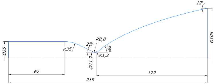
Рис. 1. Газодинамический профиль камеры двигателя
-
Fig. 1. Gas dynamic profile of the engine chamber
The calculations of the propellant mixing process and the design of the injector heads were performed using the results of experimental and analytical studies on combustion chamber flow modeling, as well as established design methodologies for low-thrust liquid rocket engines.
The injector heads, manufactured as an integral part of the low-thrust rocket engine chambers, have an identical configuration consisting of eight oxidizer jet injectors and eight fuel swirl injectors with tangential inlets. To form a protective wall film, sixteen peripheral fuel jet injectors were incorporated and separated from the main flow by a shielding ring. Protection of the electric spark igniter is provided by eight additional fuel jet injectors, which suppress high-temperature reverse flows in the igniter region (Fig. 2).
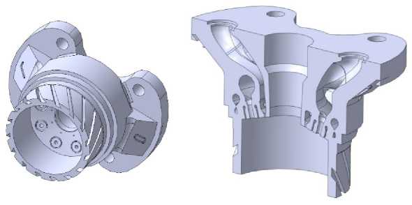
Рис. 2. 3D-модель смесительной головки
-
Fig. 2. 3D-model of the mixing head
The geometric dimensions and gas-dynamic characteristics of each injector type were calculated using dedicated design methodologies based on empirical fluid dynamics and gas dynamics correlations. The calculations yielded the injector discharge coefficients, outlet orifice areas and diameters, propellant mass flow rates, and pressure drops across the injectors. A distinctive feature of the tangential-entry swirl fuel injector is its teardrop-shaped inlet channel. To develop the three-dimensional model of the injector, the radius of the teardrop-shaped inlet profile must first be determined. For this purpose, the Reynolds number at the injector inlet was calculated, followed by verification of the assumed discharge coefficient and the gas pressure drop. The calculated radius of the teardrop-shaped inlet profile was Rk = 4,1 mm . The full spray cone angle was determined from the graphical relationship as a function of the geometric characteristic of the open swirl injector, Agts, and was found to be ag.ts = 133°48‘.
The design of the finned regenerative cooling channel addresses the integrated task of optimizing the geometry of the coolant flow passage to ensure both efficient heat transfer and the structural integrity of the engine chamber. At present, the methodology for designing finned cooling channels for rocket engines employing gaseous regenerative cooling is still under development and experimental validation. Therefore, the present study applies the fundamental principles used in the design of regenerative cooling channels for liquid rocket engine combustion chambers to calculate the cooling passages of the experimental low-thrust rocket engine chambers with helical (spiral) and meridional (longitudinal) channels. The initial geometric parameters of the cooling channel adopted for the calculations are summarized in Table 1.
Table 1
Initial Geometric Dimensions of the Cooling Channel
|
Parameter |
Symbol |
Value |
|
Channel height |
h r , mm |
2.5 |
|
Hot wall thickness |
3 st , mm |
2 |
|
Fin thickness |
3 r , mm |
1.25 |
|
Outer wall thickness |
3 st.n , mm |
1.25 |
|
Fin inclination angle relative to generatrix |
P, deg |
45 |
|
Minimum fin pitch |
t min , mm |
2.5 |
|
Maximum fin pitch |
t max , mm |
5 |
Table 1 indicates that the inclination angle of the helical fins relative to the generatrix is β = 45°, which was selected taking into account the optimal value for 3D printing technology. For the chamber with meridional channels, the inclination angle is β = 0°.
At the initial stage of the calculation procedure, the channel parameters are determined taking into account the hot-wall thickness in fifteen conventionally selected cross-sections perpendicular to the chamber axis. Next, the number of fins in each cross-section is calculated, with rounding down to the nearest integer, while ensuring a doubled-value constraint is satisfied. The next step of the computational methodology involves determining the geometric parameters of the cooling channel, including the equivalent gas-dynamic diameter in each cross-section, channel height, fin thickness, channel width, and other related dimensions. The resulting geometric parameters of the channel form the primary numerical basis for developing the mathematical model required for 3D printing of the investigated chambers using the ASTRA 420 printer.
Optimization of the Experimental Chamber Design for Ground-Based Hot-Fire Testing
During the implementation of the scientific and educational project “Development, additive manufacturing by selective laser melting, and testing of a low-thrust rocket engine demonstrator operating on environmentally friendly propellant”, two full-scale combustion chamber specimens without regenerative cooling were previously tested on the test bench of Reshetnev Siberian State University of Science and Technology. During visual observation, a stable formation of a flame plume with flow separation from the wall surfaces at the nozzle exit was recorded. This phenomenon is attributed to nozzle operation in an overexpanded regime due to the ambient barometric pressure ( P n = 0,1 MPa) exceeding the calculated gas pressure at the nozzle exit ( P a = 0,00085 MPa) [15].
To adapt the design of combustion chambers with regenerative cooling for testing at the Keldysh Center, an analytical simulation of the nozzle gas-dynamic profile was performed using the SolidWorks Flow Simulation software package. As a result of graphical model development, several nozzle profile variants with different expansion ratios (F) were obtained (Figs. 3, 4).
Based on the characteristics of the 3D printing process using the Astra 420 printer and the design constraints associated with the placement of the coolant supply manifold on the expanding section of the nozzle, the configuration with an expansion ratio of Fa = 10 was selected as the optimal option for experimental investigations. This design does not preclude a slight overexpansion regime of the gas flow.
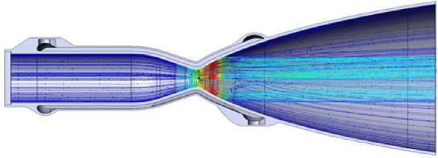
Рис. 3. Траектория продуктов сгорания в сопле с рабочей степенью расширения Fa = 80
Fig. 3. The trajectory of combustion products in a nozzle with an operating degree of expansion of Fa = 80
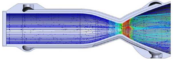
Рис. 4. Траектория продуктов сгорания в сопле с рабочей степенью расширения Fa = 10
Fig. 4. The trajectory of combustion products in a nozzle with an operating degree of expansion of Fa = 10
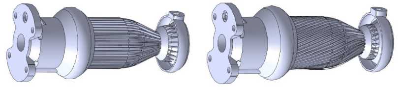
Figure 5 presents 3D models of experimental low-thrust rocket engine combustion chambers featuring meridional (longitudinal) and helical (spiral) regenerative cooling channels, designed without an external chamber wall.
b
Рис. 5. 3D-модели экспериментальных камер: а – камера с меридиональными каналами; b – камера с винтовыми каналами
Fig. 5. 3D-models of experimental chambers: a – chambers with meridional channels; b – cameras with helical channels
The regenerative cooling calculations performed during the design of the experimental chambers were validated during hot-fire ground testing. The test results are presented in the final section of the paper.
Development and Optimization of Additive Manufacturing (3D Printing) Technology for the Low-Thrust Rocket Engine Chamber
To ensure the required print quality, the first stage involved optimization of the thermal regime and support structures. During prolonged laser exposure, heat accumulates in the part being built, leading to overheating and pore formation [16–18]. To improve heat dissipation from the component, dedicated heat sinks were introduced during the digital model preparation stage in addition to conventional support structures. These elements enhance adhesion of the part to the build platform and enable efficient heat transfer from the part to the massive build platform (Fig. 6).
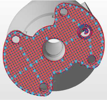
Рис. 6. Поддержки и теплоотводы в основании модели
-
Fig. 6. Supports and heat sinks at the base of the model
Preliminary printing of test bar specimens (55×11×6 mm) enabled the determination of a baseline process regime, identifying printing parameters that ensure zero porosity while maintaining maximum productivity (Table 2).
Porosity assessment was performed visually on polished cross-sectional surfaces of the bars using a digital microscope.
Table 2
3D Printing Process Parameters
|
Parameter |
Symbol |
Value |
|
Laser power |
Р |
300 W |
|
Scanning speed |
V |
900 mm/s |
|
Laser beam diameter |
D |
190 µm |
|
Hatch spacing |
s |
130 µm |
|
Idle (jump) speed |
JS |
400 mm/s |
Analyzing the 3D model of the low-thrust rocket engine, regions with a high build volume were identified. Previously obtained printing experience indicates that, to prevent overheating in areas with a larger cross-sectional area than that of the test specimens, it is necessary to reduce the specific energy input. However, a simple reduction in laser power or an increase in scanning speed leads to insufficient material fusion (lack of adequate melt penetration). On the other hand, reducing the idle (jump) speed is not efficient, as it unnecessarily increases the overall build time. To address this issue, an appropriate strategy for planning and optimizing the scan fill pattern must be implemented.
The optimal solution was the segmentation of the part contour combined with the application of an alternative scanning strategy. Instead of continuous area filling, the laser sequentially scans eight indi- vidual segments. The contour walls are formed by a 1 mm-thick border scan, while the internal region is filled using a double chessboard (checkerboard) scanning pattern (Fig. 7). This approach ensures a more uniform energy distribution across the build area, preventing localized overheating without increasing the overall build time.
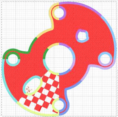
Рис. 7. Сегментация и шахматная штриховка
-
Fig. 7. Segmentation and checkerboard shading
The low-thrust rocket engine design includes internal cavities and channels. Traditionally, overhanging features require support structures, the removal of which from internal cavities after printing is often impossible. In this project, the combustion chamber was designed in accordance with the technological constraints of SLM: all overhanging features have an inclination angle of no less than 45°, which enables their fabrication without support structures (see Fig. 2).
Additionally, to compensate for melt track thickness and to simplify subsequent machining opera-
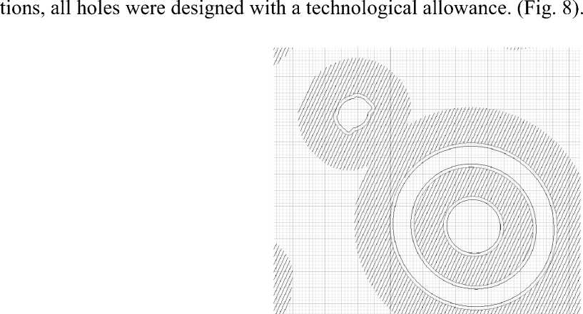
Рис. 8. Внутренняя штриховка и контуры: синий – оригинальный; красный – с отступом
-
Fig. 8. Internal hatching and contours: blue – original; red – indented
3D printing of the chambers was carried out in a vertical build orientation, as this configuration ensures the required printing quality.
Preparation of the Experimental Low-Thrust Rocket Engine for Bench Testing
For bench fire testing of the low-thrust rocket engine combustion chambers, stainless steel 12Kh18N10T nipple fittings were welded to the oxidizer and fuel inlets. In addition, a threaded adap- ter was installed to accommodate the ignition spark plug and the combustion chamber pressure sensor, Pk (Fig. 9). Fuel ignition was achieved using an SD-55AHM ceramic spark plug. The Inconel 718 alloy was welded to 12Kh18N10T stainless steel using Sv=06Kh15N60M15 filler wire under an argon shielded atmosphere.
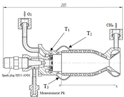
Рис. 9. Экспериментальный РДМТ
-
Fig. 9. Experimental low-thrust rocket engine
Experimental Results
Experimental investigations of two oxygen–methane low-thrust liquid rocket engine (LRE) chambers developed at Reshetnev Siberian State University were carried out at Test Facility No. 7 of the Keldysh Center.
Gaseous propellants were supplied to the engine inlet from high-pressure cylinders, with the supply pressures reduced to the values specified in the test program.
The tests were conducted under steady-state operating conditions according to the prescribed test sequence, with simultaneous commands issued to open the propellant solenoid valves and energize the ignition system. The igniter was switched off 0.2 s after the start of the ignition sequence.
The required oxygen and methane mass flow rates were supplied to the engine, and their actual values were determined using critical-flow nozzles operating under choked-flow conditions.
During the tests, pressures and temperatures of the propellant components upstream of the flowmeasuring nozzles were recorded, as well as the inlet pressures to the engine P dv " O " and P dv " G " , from which the oxidizer and fuel mass flow rates m & O and m & G were determined.
Temperatures on the external wall of the methane manifold downstream of the cooling channel ( Т 2 , Т 3 ) and on the surface of the methane bypass channel from the manifold to the injectors ( Т 1 ) were measured using chromel–alumel thermocouples (Fig. 9).
During the tests, the task of determining the limiting thermal stress conditions was not set, therefore, in the experiments, a moderate ratio of fuel components K D < 2,2 was set.
The parameters obtained during the low-thrust rocket engine tests are used to determine the mass flow parameter β using the following relationship:
Pk ‘ F kr
P = k k- , ms where Fkr - is the throat area of the engine nozzle; me - is the total propellant mass flow rate me = mO + mG •
The chamber coefficient фк is defined as the ratio of the experimentally obtained value p to the theoretical value pid at the propellant mixture ratio KD = mO and РК , corresponding to the operating mG conditions of the conducted test:
P
ф к =F Pid
К
– stoichiometric mixture ratio.
Oxidizer excess coefficient - a = —— , where KST К ST
Table 3 summarizes the results of all tests conducted on two low-thrust rocket engine chambers, with firing durations ranging from 30 to 60 s.
Table 3
Test results of chambers with longitudinal and helical cooling channels
|
No. (test) |
Й щ "° s о Я |
firing durati on |
Рdv "О" |
Рdv "G" |
Рк |
m & О |
m & Г |
m e |
K Д |
a |
в |
ф к |
Iу |
F |
|
s |
105 Pa |
105 Pa |
105 Pa |
g/s |
g/s |
g/s |
– |
– |
m/s |
– |
m/s |
N |
||
|
1 |
6 Й о |
50 |
15.9 |
26.6 |
8.4 |
37.4 |
17.7 |
55.1 |
2.12 |
0.53 |
1630 |
0.88 |
2994 |
147 |
|
2 |
30 |
16.0 |
26.3 |
8.5 |
37.3 |
17.4 |
54.7 |
2.14 |
0.54 |
1656 |
0.89 |
3048 |
148 |
|
|
3 |
60 |
16.4 |
22.4 |
8.3 |
37.0 |
17.7 |
54.7 |
2.09 |
0.52 |
1630 |
0.88 |
2992 |
146 |
|
|
4 |
60 |
16.5 |
22.6 |
8.4 |
37.1 |
17.7 |
54.9 |
2.09 |
0.52 |
1647 |
0.89 |
3023 |
148 |
|
|
5 |
30 |
16.1 |
22.5 |
8.3 |
36.2 |
17.8 |
53.9 |
2.03 |
0.51 |
1645 |
0.90 |
3011 |
145 |
|
|
6 |
60 |
16.0 |
23.6 |
8.4 |
35.9 |
19,8 |
55.8 |
1.81 |
0.45 |
1607 |
0.91 |
2930 |
145 |
The parameters given in Table 3 are averaged from the moment of reaching steady-state values until stopping, and also given are the estimated values of the specific impulse of thrust ly = I id • ф K • ф C and thrust F = ly • m e , made for the geometric expansion ratio of the nozzle F a = 100 .
Figures 10 and 11 show the variation of the measured parameters during tests of low-thrust rocket engine chambers with meridional and helical channels.
The temperature records Т 1, Т 2 and Т 3 indicate that the chambers reach a steady-state thermal regime within 15–20 s. The transition to steady-state thermal conditions in the low-thrust rocket engine chamber is also accompanied by an increase in the hydraulic resistance of the cooling channels and fuel injectors, which is manifested by a rise in pressure P dv"G" during the initial stage of the test.
Figure 12 shows the dependence of the mass flow parameter on the propellant mixture ratio.
Two low-thrust rocket engine chamber variants with identical injector configurations demonstrated virtually identical combustion performance, characterized by relatively high values of the mass flow parameter, фр = 0,88...0,91 .
The stability of the low-thrust rocket engine chamber parameters during long-duration testing and their post-test condition indicate that the chamber with meridional channels maintained operability after a total firing time of 80 s at operating conditions with a mixture ratio of KD = 2,12...2,14 and chamber pressure of PK = 8,4...8,5 • 105 Pa. For the chamber with helical channels, the total firing time was 210 s at operating conditions with a mixture ratio of KD = 1,81...2,09 and chamber pressure of PK = 8,3...8,4 •Ю5Pa.
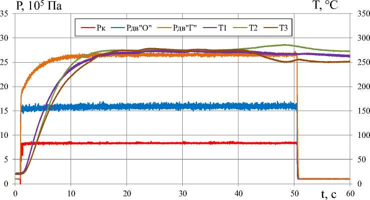
Рис. 10. Изменение параметров работы РДМТ с меридиональными каналами в процессе испытания № 1 ( in s = 55,1 г/с, Кд = 2,12)
-
Fig. 10. Changing the parameters of the RMT with meridional channels during test No. 1 ( ni s = 55.1 g/s, Km = 2.12)
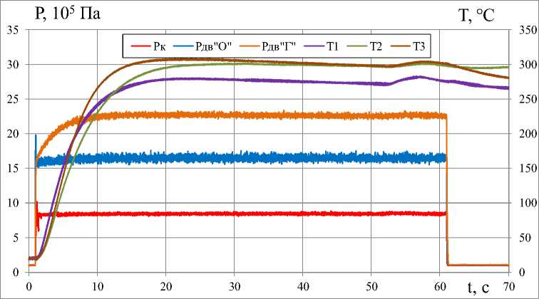
Рис. 11. Изменение параметров работы РДМТ с винтовыми каналами в процессе испытания № 4 ( m s = 54,9 г/с, Кд = 2,09)
-
Fig. 11. Changing the parameters of the RMT with screw channels during test No. 1 ( m E = 54.9 g/s, Km = 2.09)
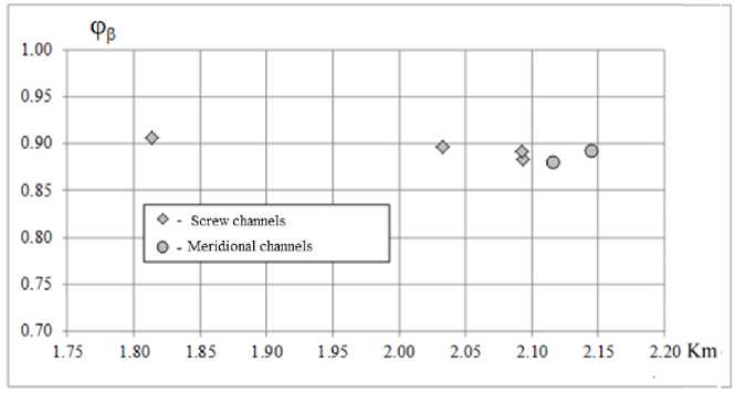
Рис. 12. Зависимость коэффициента расходного комплекса от соотношения компонентов топлива
-
Fig. 12. Dependence of the coefficient of the consumption complex on the ratio of fuel components
Upon completion of the tests, tomographic examinations of the low-thrust rocket engine chambers were performed.
Results of Tomographic Studies
The study was carried out using an X-ray computed tomography scanner [19]. As a result of scanning and subsequent analysis of the obtained images [20] of the low-thrust rocket engine chambers with meridional and helical channels, no residual powder was detected in the cooling channels
The tomographic study provided data on the as-built geometric dimensions of the low-thrust rocket engine chamber components (Table 1), which affect the operating process characteristics and thermal state.
As an example, Fig. 13 illustrates channel dimension measurements and cooling-channel wall thickness analysis for the low-thrust rocket engine chamber with meridional channels.
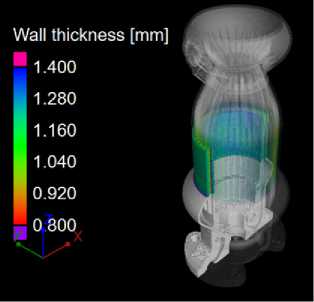
Рис. 13. Измерение каналов и толщин стенок камеры с меридиональными каналами: а – анализ толщин стенок; b – размеры каналов охлаждения
Fig. 13. Measurement of channels and wall thicknesses of a chamber with meridional channels: a – analysis of wall thicknesses; b – sizes of cooling differences
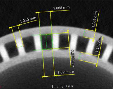
b
Fig. 14 shows a diagram of the distribution of one of the monitored parameters – the hot-gas wall thickness in the cylindrical section of the chamber, δst.
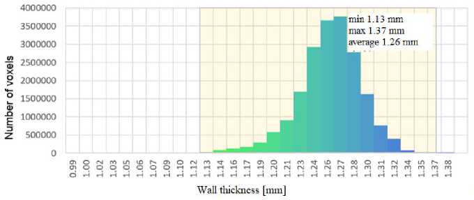
Рис. 14. Диаграмма распределения толщин огневой стенки цилиндрической части камеры δ ст (камера с меридиональными каналами)
-
Fig. 14. Diagram of the thickness distribution of the firing wall of the cylindrical part of the chamber δ st (chamber with meridional channels)
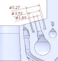
The injector region exhibits the highest X-ray path length in the investigated samples; therefore, the internal geometry cannot be determined with sufficient accuracy in this area. Figures 15 and 16 show a comparison between the scan results (light gray regions) and the initial design model (green lines).
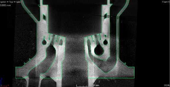
Рис. 15. Сопоставление данных томографии с исходной моделью для камеры с винтовыми каналами
-
Fig. 15. Comparison of tomography data with the initial model for a camera with helical channels
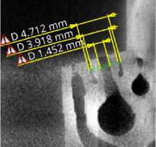
Рис. 16. Размеры форсунки камеры с винтовыми каналами
-
Fig. 16. Dimensions of the chamber nozzle with helical channels
The conducted studies revealed that deviations of the controlled geometric parameters (Table 1) from the initial model on the cylindrical portion of the chamber do not exceed 8 % downwards and
13% upwards. The maximum deviation was found in the nozzle's critical section, where the measured height of the cooling channels is 20 % higher than the initial value.
Analysis of the thermal state
In order to evaluate the thermal state of the chambers during the tests, cooling calculations were performed in the corresponding modes, which were carried out according to the standard method for calculating the cooling of the chambers of cruise liquid-propellant rocket engines using the mixture formation model adopted during the design.
According to this model, it was assumed that under nominal operating conditions ( К^т = 1,77 и pnom = 10 . 10 5 pa ) , a near-waii layer with a constant mixture ratio of K^ = 0,468 exists along the entire chamber length. The experimental values of the mass flow parameter presented in Table 3 are consistent with this model.
Since the hot-fire test conditions differed somewhat from the nominal ones, the mixture ratio in the near-wall layer used in the cooling calculations was adjusted to the conditions of each specific hot-fire test according to the following equation:
nom
K ps = K ps
•
KDexp nom KD
As practice shows in calculating cruise liquid propellant rocket engines, this method is quite acKexp ceptable if the differences D from KDnom are not very large.
In the calculation of heat transfer in the cooling channels, an empirical correlation previously developed at the Keldysh Center for heat transfer to methane was used. In addition, the effect of increased surface roughness of the channels manufactured by additive manufacturing was taken into account in the cooling-channel heat transfer calculations. For this purpose, corresponding heat-transfer enhancement factors were introduced into the model.
In addition, deviations of the combustion products composition from equilibrium were taken into account under the prevailing low Kps conditions, as well as flow separation of the combustion products from the wall in the diverging section of the nozzle during ground testing.
To determine the non-equilibrium composition of the combustion products, a previously developed semi-empirical model of incomplete methane–oxygen combustion at the Keldysh Center was used.
The influence of flow separation in the nozzle on the thermal state was approximately accounted for by assuming zero heat flux along the section extending from the cross-section where the combustion products pressure is 8,4 - 10 5 Pa to the nozzle exit plane.
The calculation results are presented in Figs. 17–19.
In Fig. 17–19 the following notations are used: Tst.g – wall fire surface temperature; Tst.x – wall temperature on the cooler side; Tohl – cooler temperature. The x coordinate in Fig. 17–19 is measured according to Fig. 9.
Wall temperatures in the initial section of the chamber (as x → 0) are apparently overestimated, since the near-wall layer is not yet fully developed in this region; therefore, the mixture ratio near the hot-gas wall remains significantly lower than that assumed in the computational model. Taking this into account, it can be concluded that the chamber wall temperatures during the tests were at a safe level, which is also confirmed by the absence of any damage to the hot-gas wall.
To verify the validity of the thermal state predictions presented above, the calculated values of fuel heating in the cooling channel are compared with the corresponding experimental data.
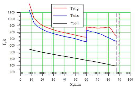
Рис. 17. Расчетные характерные температуры камеры с прямыми каналами охлаждения на испытании № 1 (P к = 8,4∙105 Па, Kд = 2,12)
Fig. 17. Calculated characteristic temperatures of the chamber with direct cooling channels in test No. 1 (Pк = 8.4∙105 Pa, Km = 2.12)
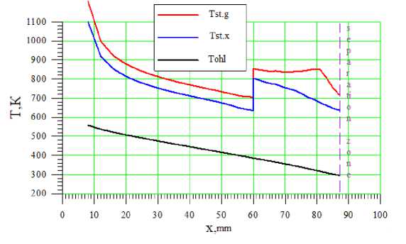
Рис. 18. Расчетные характерные температуры камеры со спиральными каналами охлаждения на испытании № 3 (Pк = 8,3∙105 Па, Kд = 2,09)
-
Fig. 18. Calculated characteristic temperatures of the chamber with spiral channels in test No.3 (P к = 8.3∙105 Pa, K m = 2.09)
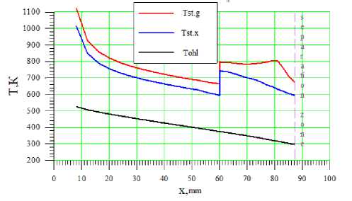
Рис. 19. Расчетные характерные температуры камеры со спиральными каналами охлаждения на испытании № 6 (Pк = 8,4∙105 Па, Kд = 1,81)
-
Fig. 19. Calculated characteristic temperatures of the chamber with spiral channels in test No. 6 (Pк = 8.4∙105 Pa, Km = 1.81)
In order to enable such a comparison, each tested chamber was equipped with three chromel– alumel thermocouples ( Т 1 , Т 2 , Т 3 (see Fig. 9)), with their hot junctions welded to the external chamber casing. Externally, the thermocouples were thermally insulated using several layers of quartz tape. Due to sufficiently intense heat transfer between the fuel flowing through the cooling channel and the inner surfaces of the manifold and bypass duct, heating of the outer wall occurred. The thermal insulation minimized heat losses from the outer wall to the surrounding environment; therefore, after a certain operating time under steady-state conditions, the outer wall reached a temperature approximately equal to the steady-state coolant temperature at the outlet of the cooling channel. The inlet temperature to the cooling channel, Tfuel was measured directly in the fuel flow using a resistance thermometer. These measurements made it possible to accurately estimate the experimental fuel heating in the cooling channel under steady-state chamber operating conditions.
The typical time history of thermocouple readings Т 1, Т 2, Т 3 during the hot-fire test is shown in Figs. 10 and 11. The experimental fuel heating values are presented in Table 4.
Table 4
Experimental Fuel Heating Parameters in the Cooling Channel
|
Test |
P K |
K D |
m & G |
P dv”O” |
T G |
exp Δ Tcool |
rachs Δ Tcool |
|
105 Па |
г/c |
105 Па |
К |
К |
К |
||
|
No. 1, meridional channels |
8.4 |
2.12 |
17.7 |
26.6 |
291 |
253 |
257 |
|
No. 3, helical channels |
8.3 |
2.09 |
17.7 |
22.4 |
295 |
254–283 |
263 |
|
No. 6, helical channels |
8.4 |
1.81 |
19.8 |
23.6 |
296 |
201–233 |
228 |
The experimental fuel heating was determined as the difference between the steady-state readings of thermocouples Т 1 , Т 2 , Т 3 and the inlet fuel temperature T fuel. at the engine inlet.
In Table 4, for tests No. 3 and 6, the experimental fuel heating in the cooling channel is presented as a range due to slight discrepancies in the temperature readings of Т 1, Т 2, Т 3.
The observed good agreement between the calculated and experimental fuel heating indicates sufficient reliability of the computed chamber thermal state presented in Figs. 17–19.
As demonstrated by the tomographic studies, the actual geometric characteristics of the chambers differ from the nominal design values. With regard to the thermal state, the most significant deviations of the as-built dimensions from the nominal ones are as follows:
-
– the cooling-channel rib thickness is uniformly 8 % greater than the nominal value;
-
– at the throat section, the cooling-channel height is 20 % greater than the nominal value.
The above deviations are observed both in the chamber with straight channels and in the chamber with helical channels. To assess their influence on the thermal state, an additional cooling analysis was performed for the chamber with helical channels using geometric parameters that closely match the as-built configuration. The results of the calculations show that the coolant heating remains unchanged, while the wall temperature increases by 30 ° at the throat section and decreases by 10 ° in the cylindrical section compared to the values presented in Figs. 17–19. It is evident that such variations in wall temperature are not of primary importance and do not affect the previously drawn conclusion regarding the adequacy of chamber cooling.
Conclusion
-
1. As part of a collaborative research program between Reshetnev Siberian State University of Science and Technology and the JSC “Keldysh Research Center”, an experimental campaign was conducted at the Keldysh Research Center's test facilities to evaluate two prototypes of 200 N nominal-thrust low-thrust rocket engine combustion chambers operating on gaseous oxygen and methane propellants. The low-thrust rocket engine combustion chambers were designed by Reshetnev Siberian
-
2. Two hot-fire tests of the low-thrust rocket engine combustion chamber incorporating meridional regenerative cooling channels were conducted with firing durations of 30 and 50 s, respectively. In addition, four hot-fire tests of the combustion chamber featuring helical regenerative cooling channels were performed with firing durations ranging from 30 to 60 s. As a result of these hot-fire tests, steady-state thermal operating conditions were achieved in the low-thrust rocket engine combustion chambers, enabling the determination of their principal performance parameters and demonstrating the operational capability of the experimental combustion chamber designs.
-
3. Two variants of the low-thrust rocket engine combustion chambers featuring identical injector element configurations demonstrated nearly identical combustion process quality, characterized by relatively high values of the flow coefficient complex φβ = 0.88–0.91.
-
4. After completion of the tests, the low-thrust rocket engine chamber assemblies were examined using X-ray computed tomography, enabling the determination of the distribution of actual geometric dimensions along all spatial coordinates of the chambers, as well as deviations from the original design model. The tomographic results demonstrate acceptable manufacturing accuracy for structures with complex geometries, including the cooling passage architecture, internal channels, and injector elements.
-
5. The level of the experimental value of the consumption complex and the results of comparison of the calculated and experimental values of fuel heating in the cooling tract indicate the reliability of the mixture formation model adopted during the design, including the formation of the wall layer.
-
6. The good agreement between the calculated and experimental fuel heating in the cooling channel confirms the correctness of the thermal state predictions for the chambers presented in this study.
-
7. The results of this work confirm the possibility of using methods for calculating the thermal state of the chambers of cruise liquid propellant rocket engines to calculate the parameters and characteristics of the thermal state of the chambers of low-thrust rocket engines.
State University of Science and Technology and manufactured by Polychrom LLC using the advanced Selective Laser Melting (SLM) additive manufacturing process.