
Design of a composite anisogrid cylindrical shell
Journal: Siberian Aerospace Journal @vestnik-sibsau-en
Section: Aviation and spacecraft engineering
Article in issue: 2 vol.27, 2026.
Free access
Shells of rotation made of composite materials are often used as force elements of structures in the production of rocket and space technology. Composite shells have a high degree of weight perfection provided by high specific mechanical characteristics of composites. They are manufactured by the method of continuous winding of composite fibers on a mandrel of the required shape. The method is widespread due to its manufacturability and guarantees reliable provision of design parameters of the shells. Anisogrid cylindrical and conical shells in recent years have also started to be used in RCT. For example, at Reshetnev JSC, this type of shells are used in the designs of adapters intended for launching spacecraft and satellites into orbit. Adapter structural elements are similar, but differing in purpose, dimensions and bearing capacity, they have a unique combination of a large number of design parameters, the exact determination of which every time results in a complex scientific task. The solution to this problem involves numerous design calculations of the stress-strain state, critical loads and stiffness parameters. For this purpose, a digital twin is formed on the basis of a finite element model of anisogrid shells of rotation, manufactured by continuous winding of composite fiber, with the help of which the solution of the optimal design problem is performed in interactive mode. An algorithm and a program for constructing a composite anisohydric cylindrical shell with concentrated mass on one base and with a rigidly fixed second base are developed. Numerical analysis of stability, stiffness and stress-strain state of the structure under different variants of inertial action and at variation of parameters of its mesh structure formation is carried out with the help of FEM.
Short address: https://sciup.org/148333985
IDS: 148333985 | UDC: 539.3 | DOI: 10.31772/2712-8970-2026-27-2-302-315
Text of the scientific article Design of a composite anisogrid cylindrical shell
The analysis of the behavior of thin-walled composite elements of RCT has received considerable attention in the modern scientific literature [1-3]. This is due to a number of properties of composites that distinguish them from traditional structural materials. These properties, taken into account in theoretical models, must be reflected in practical calculations of rocket and space structures, the accuracy of which is subject to increased demands.
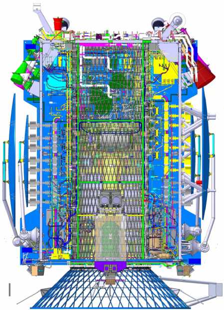
The design of composite lattice structures has received considerable attention in recent years [415]. Previously, a study was conducted on the influence of the basic design parameters of anisogrid cylindrical and conical shells on their rigidity and load-bearing capacity under end loading by various force factors, the results of which are presented in [16-18]. The paper [17] describes the design of a conical lattice shell with a fixed lower base, loaded with a complex of forces on a small base. Such a shell is present in the design of an adapter (Fig. 1) designed for launching satellites into orbit. In that work, the stability criterion is used to optimize the design parameters (number and angles of helical fins, cross-sectional dimensions of the fins) under constraints on the adapter structure’s mass. In another work by the author [19], a similar study was conducted for a grid-like conical shell with a fixed small base and loaded with a complex of forces on the larger base. This type of anisogrid conical shell with a reverse taper, in which the small base is fixed and the force is simulated by a system of end forces applied to the larger base, is proposed as an alternative to frame or truss conical load-bearing elements currently used in some spacecraft (Fig. 2).
1Н!НШ(1Я
HOTSW
Рис. 1. Адаптер для вывода спутников системы ГЛОНАСС

Fig. 1. Adapter for displaying satellites of the GLONASS system
Рис. 2. Ферменная конструкция разгонно го блока типа «ФРЕГАТ»
Fig. 2. Truss structure of the FREGAT type upper stage
In the present work, an anisogrid cantilever-fixed cylindrical shell loaded by a concentrated mass at the free end is considered. The influence of a number of basic design parameters of the lattice structure on the stress state, stability and stiffness under various variants of inertial loading is investigated.
Modeling a Cylindrical Mesh Shell and Algorithmization of the Numerical Study
A typical cylindrical mesh shell consists of two systems of spiral ribs and a system of annular ribs. The systems of spiral ribs are laid out along geodesic lines at angles of ±φ to the generatrix of the cylindrical surface. The annular ribs divide the segments of the spiral ribs located between their intersection points into equal parts (Fig. 3).
The initial data for creating the geometric model of the mesh structure are the length L and the diameter D of the shell, the number of spiral ribs in the same direction n , and the inclination angle of the spiral ribs φ.
The geometric model of the shell is formed using a typical segment of the mesh structure (Fig. 4).
The dimensions of a typical segment (Fig. 4) are determined using the basic design parameters:
S = π D/n , l = π D/ 2 n tg φ.
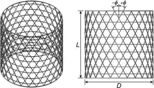
Рис. 3. Сетчатая цилиндрическая оболочка общего вида
Fig. 3. General view anisogrid cylindrical shell
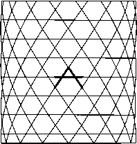
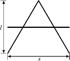
Рис. 4. Типовой сегмент сетчатой структуры
Fig. 4. Typical mesh structure segment
The number of annular ribs increases as the number of helical ribs and their inclination angle φ increase.
First, a finite element model of the typical segment is constructed. This is done using spatial beam finite elements (BEAM3D). The shapes and dimensions of the cross-sections and the material properties of the helical and annular ribs may differ. These parameters are specified in element property groups. The finite element model of the complete mesh cylindrical shell is created using copy, rotate, and translate operations on the finite element mesh of the typical segment. The geometric and elastic parameters of the annular ribs located at the edges of the shell may differ from those of the annular ribs of the main mesh structure. This allows for the simulation of the installation of end frames through which the shell is loaded with forces and moments.
Previous studies [16; 18] have shown that to increase the load-bearing capacity and rigidity of the adapter, it is advisable to supplement the mesh structure of the cylindrical section with a system of longitudinal ribs (Fig. 5), the cross-sectional dimensions of which generally differ from the crosssectional dimensions of the main mesh ribs (spiral and annular). It should be noted that the longitudinal ribs are divided into groups of varying lengths. They are all attached at one end to the lower frame. Thus, the mesh cylindrical shell contains zones with varying longitudinal rigidity, the highest value of which is at the bottom, directly at the fixed edge.
To determine the optimal design parameters for a mesh cylindrical shell, a comprehensive numerical study is required, which involves conducting numerous standard calculations with various combinations of input data. Therefore, it is advisable to develop an algorithm and program for automatically constructing geometric and finite element models of an arbitrary mesh cylindrical shell design.
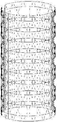
Рис. 5. Сетчатая цилиндрическая оболочка с дополнительной системой продольных ребер
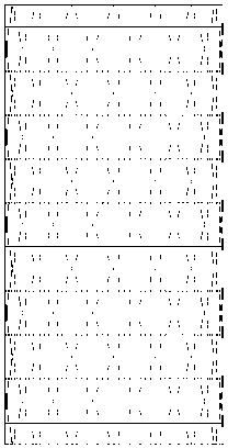
Fig. 5. Anisogrid cylindrical shell with an additional system of longitudinal ribs
The algorithm described above for generating geometric and finite element models of a mesh cylindrical shell was implemented as a program written in the internal language of the COSMOS/M package. The program enables automatic construction of finite element models of mesh shells with a variety of geometric and elastic parameters. This enables rapid analysis of the load-bearing capacity of mesh cylindrical shells.
The set of basic design parameters for an anisogrid cylindrical shell includes the shell diameter and height, the number of spiral ribs, the winding angle of the spiral ribs, the cross-sectional dimensions of the ribs, and the material properties.
For certain types of calculations, automatic assignment of typical loads and boundary conditions can be provided (Fig. 6).
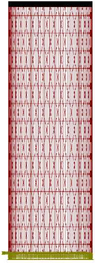
Рис. 6. Сетчатая цилиндрическая оболочка с закрепленным нижним основанием и сосредоточенной массой на верхнем основании
Fig. 6. Anisogrid cylindrical shell with a fixed lower base and concentrated mass at the upper base
To analyze the strength, stability, and rigidity of the cylindrical portion of the adapter, a cantilevered support system with a lower base and an equivalent load (2500 kg) applied to the upper frame was chosen (Fig. 6).
For fixed overall dimensions of the lattice cylindrical shell, the most important parameters affecting its performance are the winding angles and the number and cross-sectional size of the spiral ribs. In the author’s work [16], in particular, it was shown that the load-bearing capacity of the shells depends significantly on the winding angles of the ribs. An analysis of the axial compression stability of lattice cylindrical shells of varying lengths was performed (Fig. 7), and graphs of the critical loads versus the angle φ were obtained. These graphs demonstrate that shells of different lengths have their own optimal values for these angles.
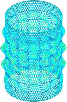
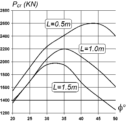
Рис. 7. Форма потери устойчивости цилиндрической сетчатой оболочки при осевом сжатии и графики зависимости критического усилия ( P cr) от величины углов намотки спиральных ребер (ϕ°) для моделей различной длины ( L )
Fig. 7. The form of buckling of a cylindrical mesh shell under axial compression and graphs of the dependence of the critical force (Pcr) on the magnitude of the winding angles of the spiral ribs (ϕ°) for models of various lengths ( L )
Numerical Study
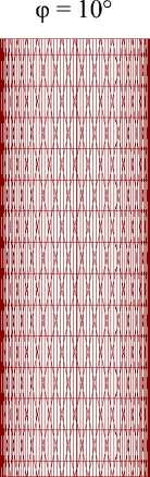
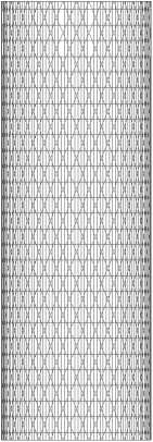
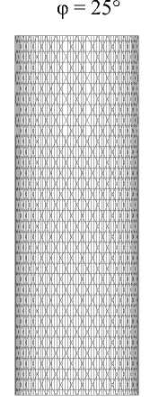
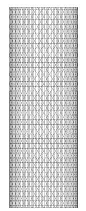
A comprehensive study of the dependence of the stress-strain state, critical loads, and stiffness of cylindrical lattice shells, cantilevered at one end and with a concentrated mass at the other, under typical inertial loading conditions simulating the overloads experienced during the orbital insertion phase of a spacecraft will be conducted. The models with different winding angles of the spiral ribs will be considered (Fig. 8). The remaining parameters of the lattice shell remain unchanged:
-
– diameter – 1.2 м;
-
– height – 3.5 м;
-
– number of spiral ribs of one family – 36;
-
– cross-sectional dimensions of the spiral and annular ribs – 15 x 3 mm;
-
– cross-sectional dimensions of the longitudinal ribs – 15 x 4.2 mm;
-
– longitudinal modulus of elasticity, carbon fiber reinforced plastic –180 GPa;
– density – 1550 kg/m3.
The results of the study are presented in Tables 1 and 2 and in Figures 9–16.
The first numerical experiment investigated the stress state and stability of a shell with a helical rib wrap angle of φ=10° under an axial overload of 6G. The maximum stresses (56.48 MPa, Fig. 9) occurred in the helical ribs of the middle zone and did not exceed the permissible compressive stress (200 MPa) for carbon fiber reinforced plastic. The stress diagram shows the number of the finite element with the highest von Mises stress.
The buckling factor (8.63) is also quite large. The buckling pattern (Fig. 9) corresponds to uniform compression with simultaneous bending of all sections of the helical ribs.
φ = 15°
«■■^^^^^^^ П1ИШШ!111ВИШ^ ИИСЕ1№
ИМН1Н
ИМСЕ1№ in»»ii»iiiiDi: имн ■■«■^^^^^ И1МСМ ■■■■■^ HMCElit
ИМН1№ HIM^iH ИМН1№ ■■■■■■■IM wmtni
φ = 20°
φ = 30°
φ = 35°
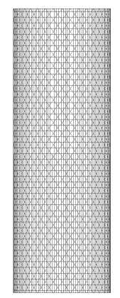
Рис. 8. Сетчатые цилиндры с различными значениями угла намотки спиральных ребер
Fig. 8. Mesh cylinders with different winding angles of spiral fins
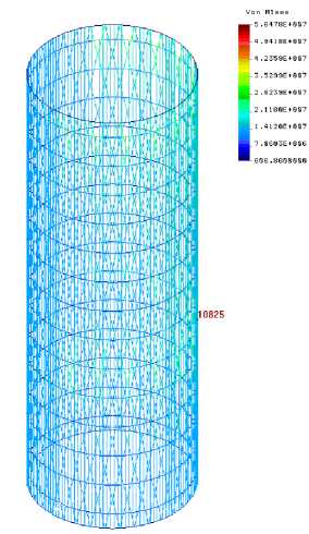
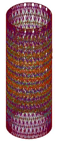
Рис. 9. Напряжения Мизеса и форма потери устойчивости модели (φ = 10º) при осевом сжатии 6G
Fig. 9. Mises stress and buckling mode of the model (φ = 10º) under axial compression 6G
Table 1
Maximum equivalent stresses and critical safety factors of lattice cylindrical shells with a load at the free end and different winding angles of the helical ribs under various inertial load variants
|
φ, deg |
m, kg |
Axial compression, 6G |
Bending: axial compression, 6G transverse overload, 2G |
Transverse overload, 3G |
Bending and torsion |
||||
|
Mises |
K cr |
Mises |
K cr |
Mises |
K cr |
Mises |
K cr |
||
|
10 |
68.49 |
56.48 |
8.629 |
227.26 |
1.74 |
322.36 |
2.25 |
288.64 |
1.36 |
|
15 |
68.78 |
49.15 |
14.14 |
186.65 |
3.96 |
230.77 |
3.03 |
215.89 |
3.12 |
|
20 |
69.45 |
59.94 |
22.46 |
175.64 |
7.69 |
200.05 |
6.45 |
171.60 |
6.22 |
|
25 |
69.94 |
55.61 |
28.26 |
168.36 |
10.0 |
193.31 |
8.82 |
164.43 |
8.97 |
|
30 |
71.52 |
52.65 |
36.47 |
159.37 |
12.57 |
184.09 |
11.01 |
160.03 |
11.22 |
|
35 |
73.76 |
50.21 |
44.29 |
150.51 |
14.78 |
174.44 |
12.93 |
160.74 |
13.20 |
Table 2
Natural frequencies of cylindrical mesh shells with a load at the free end and various spiral fin winding angles
|
φ, deg |
m, kg |
Natural Frequencies , Hz |
||
|
beam |
torsional |
Shell (o), Second beam (b) |
||
|
10 |
68.49 |
5.61 |
8.25 |
63.90 (o) |
|
15 |
68.78 |
7.33 |
11.4 |
74.30 (o) |
|
20 |
69.45 |
8.90 |
15.05 |
71.26 (b) (*) |
|
25 |
69.94 |
9.70 |
17.34 |
68.99 (b) |
|
30 |
71.52 |
10.22 |
19.83 |
66.53 (b) |
|
35 |
73.76 |
10.50 |
21.72 |
64.54 (b) |
(*) The second beam shape is shown in Figure 14.
If transverse overload is added, the deformation pattern will correspond to the case of transverse bending (Fig. 10). The zone of maximum stress (Fig. 11) is classically localized at the bottom, closer to the fixed end. In this case, the acting stresses (227.26 MPa) are higher than the permissible values, and the safety factor (1.74) drops sharply compared to the case of strict axial compression. Individual sections of the spiral ribs (Fig. 11) in the middle and upper zones of the lattice structure lose stability, where the lengths of these sections are greater (due to the absence of longitudinal ribs in this area) than in the lower part of the cylinder.
The stress state of the structure will be aggravated if the inertial force from rotation around the longitudinal axis is added (Fig. 12). The maximum stress in the hazardous area (element No. 899, Fig. 12) will reach 288.64 MPa, which is 1.5 times higher than the permissible values.
It should be noted that the intensity of the stress state is difficult to predict in complex structures such as the mesh composite structure. For comparison, the distribution of equivalent stresses under a strictly transverse overload of 3G is shown (Fig. 12, right). In the most hazardous area, element No. 70 (its location is shown in Fig. 11), the combined stresses (322.36 MPa) were higher than under combined inertial loading with bending and torsion. This underscores the importance of a comprehensive numerical study, similar to ours, conducted during the preliminary design phase.
One of the most important characteristics of the adapter is its rigidity, which must ensure the stability of the structure during its orbital insertion. Rigidity is estimated based on the magnitude of the natural vibrations. The study calculated the frequencies and shapes of the natural vibrations of the four lowest modes. The first two (orthogonal) beam modes correspond to vibrations of a lattice cylindrical shell, acting as a cantilever beam. For these modes, a model with a spiral rib winding angle of φ = 10° yielded frequencies of 5.61 Hz (Table 2). The next highest frequency (8.25 Hz) corresponds to torsional vibration about the longitudinal axis, and the third frequency presented, 63.9 Hz (Table 2), corresponds to shell vibration. Figure 13 shows the limiting positions of beam and shell vibrations. The beam mode of vibration is of practical significance in this case, since a low value of the corresponding frequency (indicating low structural rigidity) can lead to unacceptable displacement of the free end of the cylindrical shell.
With increasing spiral rib winding angles, the maximum equivalent stresses decrease, and the safety margin increases for all inertial load variants (see Table 1). The structural rigidity also increases, as evidenced by the modal analysis results (Table 2). The local jump in the maximum von Mises stresses (in the experiment with an axial overload of 6G) upon transition from the model with an orientation angle of the spiral ribs of φ = 15° to the model with an angle of φ = 20° is caused by a change in the position of the danger zone. In the model with an angle of φ=15°, this zone is localized in the middle part of the cylinder (as in the model with φ = 15°, Fig. 9), and in the model with an angle of φ = 20°, the element with the maximum stress is in the upper part of the cylindrical anisogrid structure (Fig. 14), where the mesh density is less dense. The increase in the stress intensity in the spiral ribs here (model φ = 20°) is determined by a larger angle of inclination of the longitudinal axis of the ribs to the direction of the compressive force than in the model with an angle of φ = 15°. The general trend of decreasing stresses, increasing critical loads, and increasing structural rigidity as the winding angles of the spiral ribs increase is explained by the increasing mesh density, which improves the coordination of the ribs. This is clearly demonstrated in the numerical experiment on the stability analysis of the cylindrical lattice shell. In all models with spiral-rib winding angles up to 25°, either the segments of spiral ribs lose stability together, as in strict axial compression (Fig. 9), or locally, as in bending (Fig. 11). In models with φ from 25° and above, shell-type buckling modes are realised both under axial compression (Fig. 15) and under bending (Fig. 16).
It should be noted that, despite the revealed tendencies of change in the stress-strain state, stability and stiffness of cylindrical lattice shells with increasing spiral-rib orientation angles, the optimal values of design parameters can be reliably determined only from the results of a comprehensive numerical experiment. This is due to a number of circumstances: first, the strong (sometimes unpredictable) influence of some parameters on the target characteristics (for example, a change in the winding angle of the spiral ribs by 5° (from φ = 15° to φ = 20°) led to an increase in maximum stresses by 20 %); second, the complex combination of numerous design parameters on the performance of composite lattice structures, and, as a consequence, the difficulty of choosing a solution to improve the controlled characteristics (stress-strain state, critical loads, stiffness) without a series of confirming calculations.
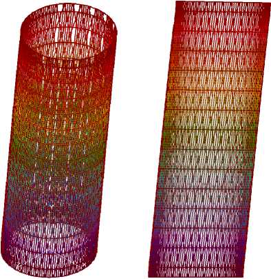
Рис. 10. Деформирование модели (φ = 10º) при изгибе (осевая перегрузка – 6G, боковая – 2G). Слева – изометрия, справа – вид сбоку
Fig. 10. Deformation of the model (φ = 10º) during bending (axial overload – 6G, lateral overload – 2G). On the left is an isometric view, on the right is a side view
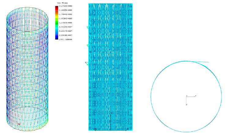
Рис. 11. Напряжения Мизеса и форма потери устойчивости модели (φ = 10º) при изгибе (осевая перегрузка – 6G, боковая – 2G)
Fig. 11. Mises stresses and the mode of buckling of the model (φ=10º) during bending (axial overload – 6G, lateral overload – 2G)
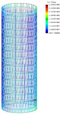
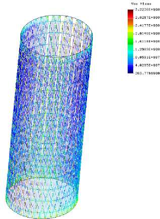
Рис. 12. Напряжения Мизеса модели (φ = 10º) при изгибе и кручении (слева) и поперечной перегрузке (опасный элемент 70, как на рис. 4)
Fig. 12. Mises stresses of the model (φ = 10º) during bending and torsion (left) and transverse overload (hazardous element 70, as in Fig. 4)
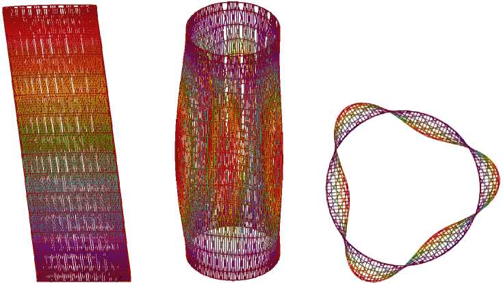
Рис. 13. Формы собственных колебаний модели (φ = 10º): балочная (слева) и оболочечная
Fig. 13. Model natural vibration modes (φ = 10º): beam (left) and shell
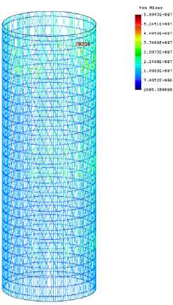
Рис. 14. Напряжения Мизеса модели (φ = 20º) при осевом сжатии 6G и четвертая мода колебаний
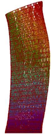
Fig. 14. Mises stress of the model (φ = 20º) under axial compression 6G and the fourth vibration mode
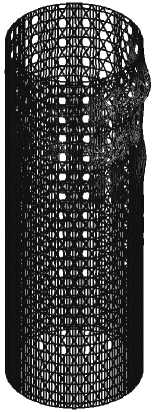
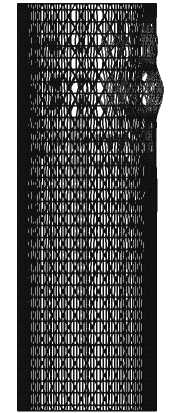
Рис. 15. Форма потери устойчивости модели (φ = 25º) при осевом сжатии (осевая перегрузка – 6G): слева – изометрия, справа – вид сбоку
Fig. 15. Form of buckling of the model (φ = 25º) under axial compression (axial overload – 6G): left – isometric, right – side view
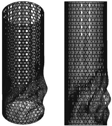
Рис. 16. Форма потери устойчивости модели (φ = 25º) при изгибе (осевая перегрузка – 6G, боковая – 2G): слева – изометрия, справа – вид сбоку
Fig. 16. Form of buckling of the model (φ=25º) during bending (axial overload – 6G, lateral – 2G): left – isometric, right – side view
The versatility of design solutions using the example of a model with a spiral rib winding angle of φ=15º will be demonstrated. Data from previous calculations (see Table 1) indicate that the maximum von Mises stresses under inertial bending and torsion loading (215.89 MPa) exceed the permissible limits for this material. One way to reduce this limit is to increase the strength of the spiral ribs. The specified cross-sectional height (15 mm) of the spiral ribs will be gradually increased, thereby increasing their flexural rigidity. Already at a rib cross-sectional height of 17 mm, the stress state will enter the permissible limits (Table 3). With a further increase in the spiral rib strength, the acting stresses will decrease further. However, with an increase in this geometric parameter (hc), the mass of the mesh structure also increases. In the model with a spiral fin cross-section height of 19 mm, the stress state will be virtually the same as in the original model with a spiral fin winding angle of φ = 20º, but the structure’s mass will be 4 kg higher. Therefore, for the considered inertial loading scenario, it is more advantageous to increase the spiral fin winding angle by 5º (from φ = 15º to φ = 20º) than to increase their power. This conclusion follows from an analysis of the results of the numerical experiment.
Table 3
Maximum equivalent stresses of a cylindrical lattice shell with a spiral fin wrap angle of φ = 15º and various cross-section heights
|
h , mm c, |
Mises, MPa |
m, kg |
|
15 |
215.89 |
68.78 |
|
17 |
191.82 |
71.22 |
|
19 |
172.58 |
73.68 |
Conclusion
As a result of this work, the dependences of critical inertial loads, frequencies and modes of natural vibrations, and the stress-strain state on the spiral fin wrap angles in composite cylindrical lattice shells, clamped at one end and with a mass attached to the other, were determined. The study has demonstrated that the optimal combination of numerous design parameters, characteristic of anisogrid structures, can only be determined through the results of a numerical experiment, the scope and thoroughness of which are comparable to the objectives and scale of the scientific research.