Design of a Virtual Area Network for National Open University Sokoto Study Center

Author: Zaharaddeen M. Bello, Bello A. Buhari, Sirajo Shehu
Journal: International Journal of Wireless and Microwave Technologies @ijwmt
Article in issue: 1 Vol.10, 2020.
Free access
Nowadays, there is a need for an efficient and effective way in which computers are interconnected. In National Open University Sokoto Study Center network there exist problems such as: more traffic which may slower the network performance, bandwidth wastage and security problems because the host and servers that are connected to Layer 2 switch are part of the same network segment. To resolve these problems we identify the networking media that best suits the network to enable person-to-person communication, determine the best network architecture that would enable effective resource sharing between all staff offices, design respective VLANs for different units, configure network addresses for each units and identify configurations required on router and switches to create VLAN’s and Inter VLANrouting. After the implementation of proposed Virtual Local Area Network in ICT unit of National Open University Sokoto study center, effective resource sharing and communication is achieved. Hence, implementation of this study is practically cost effective.
VLAN, Network, National Open University, Local Area Networks, Resource Sharing
Short address: https://sciup.org/15017171
IDR: 15017171 | DOI: 10.5815/ijwmt.2020.01.03
Text of the scientific article Design of a Virtual Area Network for National Open University Sokoto Study Center
A VLAN is a logical group of network users and resources connected administratively defined ports on a switch [2]. One of the motives for the attention placed on VLAN functionality now is the fast implementation of LAN switching that commenced two decades ago [3]. The basic reason for splitting a network into LANs is to reduce congestion on a large LAN [4]. Initially LANs were very flat—all the workstations were connected to a single piece of coaxial cable, or to sets of chained hubs [4].
VLANs provide an efficient mechanism for improving performance by localizing traffic, i.e., reducing the span of a Layer 2 broadcast packet [5].
The network infrastructure design becomes critical part for ICT section of organization recently. An important network design consideration for today's networks is creating the potential to support future expansions; reliable and scalable networks [6].
The staff offices in the National Open University Sokoto State Study Centre, Sokoto, Nigeria located within the building, have a LAN (Local Area Network) communication network that connects them, to enable sharing of resources, data transfer and information circulation among themselves.
Hosts and servers that are connected to Layer 2 switch are part of the same network segment. This arrangement poses some significant problems, which include:
-
• Cause of more traffic on the segment and may slow the network performance.
-
• Consumption of unnecessary bandwidth. As the number of devices connected to a switch increases, more broadcast traffic is generated and more bandwidth is wasted.
-
• When users from other place share a segment, undesirable information captures can occur, which may result to network security problem?
-
2. Related Works
Hubs and switches are used for the design and configuration of LANs. Collusion is one of the main reasons for switches replacing hubs [7]. Layer 2 switches emerged to alleviate the contention problem of shared media LANs [8]. Therefore, layer 2 switch is used to solve the aforementioned problems but not part of the same network as will be described in the proposed network.
These problems are what motivate us to design a virtual local area network for the study center that will resolve these listed problems.
To achieve this we identify the networking media that best suits the network to enable person-to-person communication, determine the best network architecture that would enable effective resource sharing between all staff offices, simulate and design respective VLANs for different units, configure network addresses for each units and identify configurations required on router and switches to create VLAN’s and Inter VLANrouting.
The design will cover ICT Unit, director office, accounting office, admin office and library unit, where all the users on the network have equal capabilities to communicate among themselves. The VLAN designs will not be able to show how broadcast message is passed across the network, but broadcast group and broadcast address for various groups where created.
Tanenbaum in [9] identified that each of the past three centuries were dominated by a single topology. 18th century was the era of great mechanical systems, 19th century was the age of steam engines and 20th century’s key technology was information gathering, processing as well as distribution. As the key technology of 20th century grows, then the need for more sophisticated information processing system increases. These enable the invention of different topology and network media for the design and implementation of efficient and secure networks.
Forouzan in [10, 11] clarified that research in data communications and networking has resulted in new technologies, whose first goal is to enable the exchange of data in forms as text, audio, images and video from all points in the world, especially in a network settings like National Open University Sokoto study center ICT center.
Ugomma in [12] designed a Local Area Network for the previous location of department of Mathematics Usmanu Danfodiyo University, Sokoto, which was then located at the faculty of sciences building. He study is limited to the LAN network that connected the offices of that department, which by designing a VLAN will enhance the performance of the network and security. Only suggestions of appropriate media to be used are presented without performing experiment, which can be real life or simulation experiment.
Bassey et al . in [13] re-designed project carried out on the Niger-Mills’ network to improve the operational short falls identified by the operators. The project successfully introduced this process in the Niger-mills LAN as a test run. It was further recommended that switch-model 2950/3560 be introduced to activate this function automatically.
Mathew and Prabhu in [14] had taken a configuration with 4 L2 switches and 2 L3 switches along with a router to explain the concept of Virtual Local Area Networks and Inter VLAN routing. They also, explained the technology associated with creating VLAN and maintaining VLAN. Static routing is done to provide routing of traffic among different VLAN’s.
Hossain and Zannat in [15] designed a network using Cisco Packet Tracer. They described how the tool can be used to develop a simulation model of the Pabna University of Science and Technology, Pabna, Bangladesh. The study provides into various concepts such as topology design, IP address configuration and how to send information in the form of packets in a single network and the use of virtual Local Area Network (VLANs) to separate the traffic generated by a different department.
-
3. Methodology
-
4. Current Network
The methodology used in this research is simulation. This involves the construction of an artificial environment within which relevant information and data can be generated. This involves review of current network to identify its problems. Then best networking media will be suggested and network layout to be used in solving the highlighted problems. CISCO packet tracer is used for the simulation. The simulation is performed using windows based laptop computer core i7 with 4Gb RAM and 3 GHz processor speed environment.
First, the current network is simulated to identify its weaknesses. Then, the proposed network is also simulated for verifying how these weaknesses are resolved.
The National Open University Sokoto Study Center is currently using LAN network. The network has 3 switches that are connected together using a group Cat-5 cable (twisted pair cable for carrying signals) which is connected to the switch ports using RJ-45 connector cable.
It also have 24 port switch at the central server location, the main switch from the server is connected to two switches in two ICT rooms, and it is taken to every computer through the trunking pipe in order to make the network available for the users in the room.
-
A. Blueprint of the Current Network
Blueprint of the current network is illustrated in Fig. 1. The server broadcast network to two different switches that broadcast information to different ICT rooms using cables and trucking pipe.
All hosts are placed in one local network segment which has disadvantages such as: all hosts are in one broadcast domain which causes more traffic on the segment and may result in slower network performance.
However, when users attach to the same shared segment, they share the bandwidth of the segment. The more users that attach to the shared cable means less average bandwidth for each user. If the sharing becomes too great, user applications start to suffer.
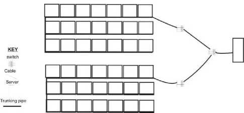
Fig. 1. Blueprint of the Current Network
-
B. Physical Toplogy of the Current Network
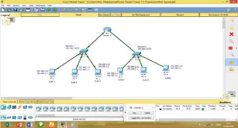
Based on the blueprint of the current network, the physical design can be illustrate as in Fig. 2 below using packet tracer showing how clients are connected to different switches on the current network.
An overall analysis of the current network is thoroughly made in a detailed manner leading to the specification of the new network. Here, task to be accomplished by separate elements of the new network will be identified.
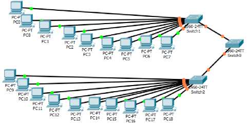
Fig. 2. Physical Topology of the Current Network
-
C. Logical Toplogy of the Current Network
Based on the blueprint of the current network, the logical design can be illustrate as in Fig. 3 below using packet tracer indicating how client are connected to different switches on the network.
-
D. Problems of the Current Network
-
5. Proposed Network
Placing all hosts in one local network segment has disadvantages such more traffic because all host are in one broadcast domain and slower network performance.
For security issues of the shared media nature of LAN networks. Whenever a station transmits in a shared network, all stations attached to the segment receive a copy of the frame, even if they are not the intended recipient.
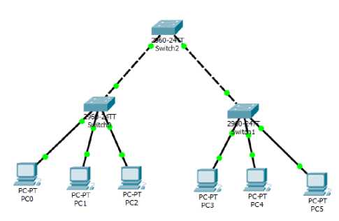
Fig. 3. Logical Topology of the Current Network
However, when users attach to the same shared segment, they share the bandwidth of the segment. The more users that attach to the shared cable means less average bandwidth for each user. If the sharing becomes too great, user applications start to suffer.
Based on the following highlighted problems new network is proposed. Here, task to be accomplished by separate elements of the new network are identified.
The importance of resource sharing and data communication over a network can never be over emphasized. In fact, the essence of networking derived from the origin was to disallow unnecessary duplication of same knowledge and to encourage sharing of knowledge centering on various aspect. It is therefore necessary to state that with the proposal of a Virtual Local Area Network in NOUN Sokoto Study center, effective resource sharing and communication will be achieved. The new network was designed using Unshielded Twisted Pair (UTP) cable even though more cost is required for its installation.
-
A. Blueprint of the Proposed Network
The proposed network in Fig. 4 consist of two 24 - ports switches (switch 0 and switch 1).Both Switches are connected to the router for the purpose of communication.
-
B. Physical Topology of the Proposed Network
Switch0 consists of a rack cabinet, and a patch panel. A group Cat-6 cable (twisted pair cable for carrying signals) is connected to the switch ports using RJ-45 connector, and it is taken to one ICT room through the trunking pipe where it is connected to the available clients in that room.Switch1 is also connected with the same connection as switch0 and also taken to another separate ICT room through trucking pipe for the available client in that room.
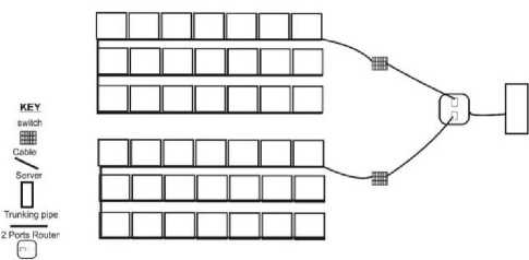
Fig. 4. Blueprint of the Proposed Network
The network is grouped into different VLAN providing different broadcasting domain. A good procedure was used while assigning each host to it respective switch and respective port for easy retrace when connection problem occurs and makes identification of the particular switch port to which an office link is connected to in case of disconnection from the network.
The physical topology of the proposed network is shown in Fig. 5.
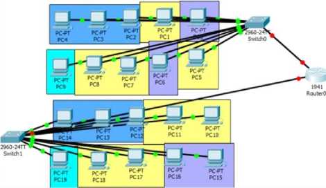
Fig. 5. Physical Topology of the Proposed Network
-
C. Logical Topology of the Proposed Network
Based on the above explanation of the proposed network the logical topology of the proposed network is shown in Fig. 6.
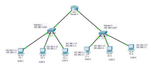
Fig. 6. Logical Design of the Proposed Network
-
D. Advantages and Benefits of the Proposed Network
The proposed network has advantages such as: splits up broadcast domains and decreases traffic, ease of administration and confinement of broadcast domain, provide increased security and it is more appropriate for large, more complex networks.
The benefits of the new network design if installed include:
-
• The network, having connects all the two different ICT rooms, will enable sharing of a single hardware devices like a printer or scanner, instead of installing one in each room.
-
• Creation of various logical groups to provide more security and more broadcast domain to the network.
-
• Easy detection and fixing of faulty port in case of any room/client that is disconnected from the network since the network design has a blue print for easy tracing.
-
• The network devices and their connections are highly protected from abuse and interruption respectively.
-
6. Proposed Network Implementation And Testing
In this section an attempt is made to implementation the proposed system and test the function of the system. The proposed design is shown in Table 1.
-
A. Implementation Steps
Step 1: Connect the equipment
-
• Connect the router gigabitethernet0/0 interface with a straight-through cable to S 0 Fa0/1 interface.
-
• Connect routergigabitetgethernet0/1 port to the Fa0/1 port on Switch 1 using a straight through cable.
Step 2: Connect the clients PC to the switch S0
-
• Connect PC 1 Fa0/0 interface from switch to the Fa0/1 on switch S 1 using straight through cable
-
• Connect PC 2 Fa0/1 interface from switch to the Fa0/0 on switch S 1 using straight through cable
-
• Connect PC 3 Fa0/2 interface from switch to the Fa0/0 on switch S 1 using straight through cable
Step 3: Connect the clients PC to the switch S 1
-
• Connect PC 1 Fa0/1 interface from switch to the Fa0/0 on switch S 1 using straight through cable
-
• Connect PC 2 Fa0/2 interface from switch to the Fa0/0 on switch S 2 using straight through cable
-
• Connect PC 3 Fa0/2 interface from switch to the Fa0/0 on switch S 2 using straight through cable
Step 4: Perform basic configurations on the switches
-
• Assign an IP addresses to every clients PC on switches S 0
-
■ Select client PC 1 on switch S 0 goto Desktop, IP address configuration assign 192.168.1.11 and assign subnet mask 255.255.255.0,default gateway 192.168.1.1
-
■ Select client PC 2 on switch S 1 goto Desktop, IP address configuration assign 192.168.1.12 and assign subnet mask 255.255.255.0,default gateway 192.168.1.1
-
■ Select client PC 3 on switch S 1 goto Desktop, IP address configuration assign 192.168.1.13 and assign subnet mask 255.255.255.0,default gateway 192.168.1.1
-
• Assign an IP addresses to every clients PC on switches S 1
-
■ Select client PC 1 on switch S 1 goto Desktop, IP address configuration assign 192.168.2.11 and assign subnet mask 255.255.255.0, default gateway 192.168.2.1
-
■ Select client PC 2 on switch S 2 goto Desktop, IP address configuration assign 192.168.2.12 and assign subnet mask 255.255.255.0, default gateway 192.168.2.1
-
■ Select client PC 3 on switch S 2 goto Desktop, IP address configuration assign 192.168.2.13 and assign subnet mask 255.255.255.0, default gateway 192.168.2.1
Table 1. Proposed Design
|
Host name |
VLAN1 |
VLAN2 |
VLAN 3 |
VLAN 4 |
VLAN 5 |
VLAN 6 |
IP Address |
Trunk |
|
RouterA |
Gigabitethernet0/0, Gigabitethernet0/1 |
|||||||
|
Switch1 |
Fa0/1, Fa0/0 |
Fa0/2, Fa0/0 |
Fa0/3, Fa0/0 |
192.168.1.0/24 |
Gigabitethernet0/0, Gigabitethernet0/1 |
|||
|
Switch2 |
Fa0/1, Fa0/0 |
Fa0/2, Fa0/0 |
Fa0/3, Fa0/0 |
192.168.2.0/24 |
Gigabitethernet0/1, Gigabitethernet0/1 |
Step 5: Perform basic configurations on the router
-
• Connect switch S1 to the router A
Router>enable
Router#configure
Router(config)#
Router(config)#interface gigabitEthernet 0/0
Router(config-if)# ip address 192.168.1.1 255.255.255.0
Router(config-if)#no shutdown
Router(config-if)#exit
-
• Connect switch S2 to router A
Router>enable
Router#configure
Router(config)#
Router(config)#interface gigabitEthernet 0/1
Router(config-if)# ip address 192.168.2.1 255.255.255.0
Router(config-if)#no shutdown
Router(config-if)#exit
-
B. Testing Steps
The router and switches should be able to ping the interfaces of the other devices.
Step 1: We test the communication of the client PC to the router
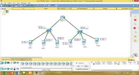
From each device, issue a ping to all interfaces. Each device should be able to ping each other in the network. The Fig. 7 shows PC 1 pings to router A. The ping is successful. But if the ping failed, try sending again. If the problem persists check the IP address of the host and default gateway.
-
Fig. 7. Ping from PC 1 to Router
From PC 5, ping to Router A. PC 5 should be able to send a ping to router A successfully. If the ping failed, resend it again maybe it’s due to the connection failure. If the problem persists, check if the host is connected to the switch port properly. The Fig. 8 shows PC 5 pings Router A successfully.
-
Fig. 8. Ping from PC 5 to Router A
By selecting 2 PC clients at random from the two different network and the ping was successful it indicate that every client PC on the network should be able to communicate successfully, failure to do so, you should try sending message or you should check the default gateway and subnet mask.
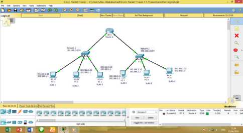
Step 2: We test the communication of the client PC on network 1 to the client on network 2
-
Fig. 9. Ping from PC 2 to PC 5
-
7. Conclution and Recommendation
The Fig. 9 shows PC 2 pings to PC 5. The ping is successful. But if the ping failed, try sending again. If the problem persists check the IP address of the host and default gateway.
The Fig. 10 shows PC 3 pings to PC 6. The ping is successful. But if the ping failed, try sending again. If the problem persists check the IP address of the host and default gateway.
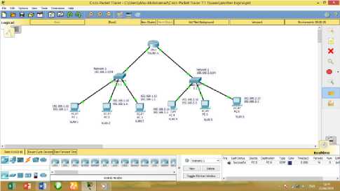
Fig. 10. Ping from PC 3 to PC 6
From the above illustrations, the test shows that the designed network connection was successful, thereby allowing the communication from one client to another.
With the deployment large number of switch ports, VLAN has become an indispensable tool for the network administration to segment the network to increase bandwidth per user, provide security and multimedia services. The evolution of VLAN as a simple broadcast containment device to a necessary function in the network, propel VLAN to be the number 1 tool in an IT professional’s bag of trick.
In this research project, an attempt has been made to network the ICT Unit of National Open University of Nigeria, Sokoto Study Center. A study of the problem domain was conducted by studying the existing networks in the center and the observed setbacks are well documented.
It is based on these setbacks that this research study among other issues was carried out to reduce (or completely eliminated) the above problems especially the problem of one broadcast domain by creating multiple broadcast domain and the amount of stress associated in finding the particular switch port each of the connected client PC is being connected to.
The new network was designed using Unshielded Twisted Pair (UTP) cable even though more cost is required for its installation.
Real life implementation of the proposed network can be performed instead of simulation, as simulation results has limited reliability, in order to effectively and efficiently evaluate the proposed network.
With regard to this conducted study, we recommend the following:
-
• This study should be fully implemented in the problem domain under consideration. This would surely be in the best interest of the entirety of the University in a bid to taking this study center to a very high standard.
-
• A modification of this study should help the tutor of this university in carrying out physical lectures to the students.
-
• A modification of this study should be carried out by intending Network Administrators and Engineers so as to bring forth a befitting network for better network performance.
-
• Security should be strictly enforced as stated while configuring the router and switches
References Design of a Virtual Area Network for National Open University Sokoto Study Center
- TechTarget Networks: (2019), Network Administration Guide., Retrieved from https://searchnetworking.techtarget.com/tutorial/Network-administration-guide.
- Pal, G. P., & Pal, S. (2013). Virtual Local Area Network (VLAN). Faculty of Electronics & Communication Engineering Department.
- Mehdizadeha, A., Suinggia, K., Mohammadpoorb, M., & Haruna, H. (2017, December). Virtual Local Area Network (VLAN): Segmentation and Security. In The Third International Conference on Computing Technology and Information Management (ICCTIM2017) (pp. 78-89).
- Tambe, S. S. (2015). Understanding Virtual Local Area Networks. International Journal of Engineering Trends and Technology, 25(4), 174-176.
- Zhu, M., Molle, M., & Brahmam, B. (2004, November). Design and implementation of application-based secure VLAN. In 29th Annual IEEE International Conference on Local Computer Networks (pp. 407-408). IEEE.
- Mulyawan, B. (2011). Campus network design and implementation using top down approach. In Proceedings of the 1st International Conference on Information Systems for Business Competitiveness (ICISBC’11).
- Hartpence, B. (n.d.). Packet Guide to Routing and Switching. Retrieved December 30, 2019, from https://www.oreilly.com/library/view/packet-guide-to/9781449311315/ch04.html.
- Layer 2 Switch. (n.d.). Retrieved December 30, 2019, from https://www.sciencedirect.com/topics/computer-science/layer-2-switch.
- Tanenbaum, A. S. (2003). Computer Networks. 4th edition. New Delhi: Prentice Hall.
- Forouzan, B.A. (2004).Data Communication and Networking. 3rd edition. New Delhi: McGraw Hill Publishing Company.
- Forouzan, B.A. (2007).Data Communication and Networking. 4rd edition. New Delhi:Kennedy Clark & Kavin Hamilton (1999). Cisco LAN Switching. Cisco Press
- Nnonyelum Ugomma Martha (2004). Design of a Local Area Network
- Bassey, D. E., Okon, B. E., & Umunnah, R. (2016). „The Security Implications of Virtual Local Area Network (VLAN), Niger Mills, Calabar, Nigeria‟. International Journal of Scientific & Engineering Research (IJSER), 7(3), 1187-1194.
- Mathew, A., & Prabhu, B. (2017). A Study on Virtual Local Area Network (VLAN) and Inter-VLAN Routing. International Journal of Current Engineering and Scientific Research (IJCESR), 4(10).
- Hossain, M. A., & Zannat, M. (2019). Simulation and Design of University Area Network Scenario (UANS) using Cisco Packet Tracer. Global Journal of Computer Science and Technology.
