Dynamic model for researching vibrations of a drum washing machine

Author: Volyanik A.Yu., Petko I.V., Pavlenko V.N.
Journal: Вестник Алматинского технологического университета @vestnik-atu
Section: Техника и технологии
Article in issue: 3 (120), 2018.
Free access
The article is devoted to the mathematical modeling of the processing of material in the drum washing and squeezing machines. The aim of the study is to develop and improve a dynamic model for studying the physical processes occurring in the oscillatory suspension system of drum machines and centrifuges. In the work, analytical expressions are obtained that establish the dependence of the forces acting on the working bodies of the device in question. The results of the study can be used in the design of household washing and squeezing machines and centrifugal devices.
Washing machine, vibrations, centrifuge, dynamics, model
Short address: https://sciup.org/140237841
IDR: 140237841 | UDC: 648
Динамическая модель для исследования вибраций барабанной стиральной машины
Статья посвящена математическому моделированию процесса обработки материала в барабанных стирально-отжимных машинах. Целью исследования является разработка и совер-шенствование динамической модели для исследования физических процессов, происходящих в колебательной системе подвески барабанных машин и центрифуг. В работе получены аналити-ческие выражения, которые устанавливают зависимости сил, воздействующих на рабочие органы рассматриваемого устройства. Результаты исследования могут быть использованы при проектировании бытовых стирально-отжимных машин и центрифугирующих устройств.
Text of the scientific article Dynamic model for researching vibrations of a drum washing machine
Forced movement of the suspension "tubedrum" in dynamics is described by a system of differential equations of the twenty-fourth and higher order, which requires complex computer programs and significant computing powers [1]. To substantially simplify the situation, we consider the motion of the hanging part in the plane of two coordinates, which implies the absence of movement of the suspension, aimed at the observer. This is possible with small fluctuations of the tube relative to the body, a very soft cuff, which in practice is possible with a properly designed drum machine.
In addition, the experimental data obtained from the results of numerous experiments make it possible to conclude that the forced movement of the suspension of the machine, with certain limitations, can be considered as a flat [4].
Objects and methods of research
The object of research is a model which is designed to study the plane-parallel motion in a vertical plane parallel to the front and back walls of the washing machine body.
Inertia elements of the machine's (Figure 1) oscillatory system: 1 - the machine body, 2 - the tube, 3 - the drum with laundry and water, belt pulley 5, the engine 4 with a pulley and a coupling.
The body rests through the elastic elements 6 and 7 on the floor.
The tube is suspended from the body by two springs 8 and 9. In addition, the body and the tube have a kinematic connection through the dampers 10
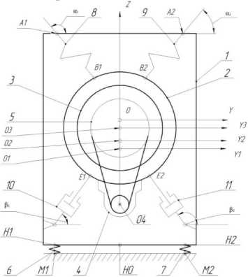
and 11. The springs 6, 7, 8 and 9 and the dampers 10 and 11 are considered as the inertial links of the system (the reaction they develop is determined by the input coordinates, and for dampers - also speeds at the current time at the input).
Four coordinate systems are used: yOz -fixed, yOz - fixedly connected to the body, y O z - fixedly connected to the tube, y O z -fixedly connected to the drum.
The centers O of the systems of rectangular coordinates ar e in the centers of mass of i-inertial bodies ( i = 1,3 ). The center of the fixed coordinate system is located in the geometric center of the loading window of the machine body in the static position. The Oy axis is horizontal. The forces of the springs are linearly dependent on the deformation.
The masses of the body (1) of the machine, of the tube (2), of the drum (3), of the motor (4) and of the laundry with water (a) will be denoted respectively as m , m , m , m and m .
The moments of inertia of the body, tube, drum, motor and laundry in relation to their mass centers denoted: IO 1 , IO 2 , IO 3 , IO 4 , I a .
The stiffnesses of the support springs 6, 7 and the springs 8, 9 of the tube suspension will be indicated accordingly: c , c and c , c , , c ( N - the number of suspension springs of the tube).
-
Fig. 1 - The calculation scheme of the drum machine.
Damper reactions (F,F , ,F , N2 - the number of dampers) are depending from the forces of dry friction and hydraulic or pneumatic resistance. In addition to the above, we take into account the elastic-dissipative properties of the cuff between the body of the machine and the tube, as well as the variability of the mass and the moment of inertia of the squeezed water.
Results and Discussion
This dynamical system, assuming a planar motion, has six degrees of freedom, the number of which is calculated on the basis of 3 stages of freedom for each free rigid body (1, 2, 3, 4) moving in a plane-parallel manner and the number of superimposed bonds. Body 1 has two stages of freedom, because the third is excluded due to the presence of a frictional connection between the body supports and the base (floor). When this friction bond breaks (when the friction force reaches a critical value), the body will have three stages of freedom. Buck brings three stages of freedom into the system. The drum 3 rotating relative to the tube 2 in the bearings adds only one stage of freedom due to the presence of two bonds in a plane perpendicular to the axis of rotation. The motor rotor does not add new stages of freedom to the system [2], because in addition to the two bonds imposed by bearings between it and the tube, another condition of communication is realized by means of a belt transmission, which we will consider as non-extendible.
It is assumed that friction in kinematic pairs due to its smallness does not affect the quantitative and qualitative characteristics of the ongoing dynamic processes.
To derive the equations of motion of the dynamic system of a machine, we use the Lagrange equations of the second kind. The total kinetic energy T of the system consists of the energies of its links 1, 2, 3, 4 and laundry (a):
T = T i + T , + T 3 + T 4 + T a . (1)
According to König's theorem [1], the kinetic energy of a solid moving in a plane-parallel manner is equal to the sum of the kinetic energies of its center of mass, in which the total mass of the body is conventionally concentrated, and the rotational motion relative to the center of mass. Thus, it is necessary to obtain analytical expressions for the velocities of the centers of mass of the links, i.e. in the function
O1 , O2 , O3 , O4 , Oa of generalized velocities and coordinates [2].
The velocity V of the center of mass of the b o dy 1 can be expressed in the transport velocity V of the point located at the base of the body (Figure 1), and the relative velocity V in the rotational motion O around point H .
Velocity V is perpendicular to the reference surface MM .
Proceeding from the above, we have
-
V O, = V H0 + V OHy = k 1 z H0 + 7 ф HOOV [ k 1 cos ф 1 - 7 1 sin Ф 1 ] =
= k [ zH0 - ф1$- HOOX sin ф 1 ] - 7 ф 7 HOOV cos *
where i - vector directed along the axis of the absolute coordinate system; j1 and k -vectors correspondingly parallel and perpendicular to the reference surface ( MM , Fig. 1); - distance between points H and O ; z - the O 1 HO projection of the absolute speed of a point H on the axis Kz perpendicular to the floor.
The expression for the velocity V of the center of mass O of the tube
VO2 = yoj + zG^k . (3)
In (3) y and z are the projections of the absolute velocity V of the center of mass O of the tube on the fixed axes Oy and Oz .
The velocity of the point V (the projection of the axis of rotation of the drum on the plane yOz ), as well as the velocities V , V , V (the centers of mass of the drum, the rotor and laundry) can be found as a result of the geometric addition of the velocities of the portable (in this case, translational) and relative motions, i.e.
V =K +y к =y
K O KO , O K OK ,
-
VO4 = К ,, + V O, O2- V O,, = V K 2 + V, K , . (4)
where the second terms of the right-hand sides are velocities in relative motion (rotational to the chosen poles O and K ).
In this way,
V KO = Цо. Ф 2^ Х [ j C0S( Ф 2 + ф O ) + k Si n( ^ + Ф2, O )] ,
V K = O^ ^ Ф з i " Х [ j cos( ^ + Ф з,о ) + k sin( Ф з + Ф з,о ) ] ,
VO4O2 = ^ O4O2 Ф 2 i x [ j СОS ф 2 + k sin Ф 2 ] , (5)
V OK = 0к ф Ф з к x [ j cos( ф з + У з о ) + k ^ф + У з о ) ] .
Here , , , are positive
K 2 O 2 O 3 K 2 O 4 O 2 O a K 2
constants (distances between points written in the indices at); ф2 о,фоузо - the angles of the phase shift (assumed as constant).
On the basis of (2), (3), (4), (5) taking into account vector products i x j = k , i x k = - j (6)
the kinetic energy of the entire system of the machine:
T =
m 1 VO 2
Io Ф 1 +—1—
+
m 2 VO
—2 +
ф Ф
mV Io. Ф з
+--- + —— +
2 2
mV' I Ф^и1 mV2 I Ф2
m 4 ' О. К ф ф4 u 43 Im V o к о фз
+ --- + —-- + --- + ~-
2 2 2 2
Expressing the kinetic energy through generalized coordinates and velocities, using the Lagrange equations of the second order, we obtain six equations of plane-parallel motion of the system.
These equations can be represented in a matrix form
Q = P HX + P H. - Z [ Pi sin a
where A - square matrix of the size 6 x 6 ,
X =[ z Ox ф 1 У о, zO. ф 2 ф 3 ] T
As a result, the generalized forces Q , are determined by the dependencies:
AX = B , (8)
k
] + XL F,sin Aj + p. sina,, j=1
Q. = P, IH cosф + z„ . sin ф1
2 H 1 H 1 ' 1 H q 1 * 1
- P, £„ cosф + z„ lsin фl
H h ' 1 H(D 1 ' 1
nk
Q3 =2 (Pi cos ai) - 2 (Fj cos Л ) - Pm cos ac , i=1
nk
Q4=- m 2 eg + 2(Psin a)- 2(Fjsin A)- pmsin ac, i=1
n
Q5 =2 (yB- Уо.)Psin a - (zB- zo2 )Pcos a + mtp sin(фз- i=1 L
Q 6 = M dU 43 - M b - M TP Sin( ф 3 - ф 2 ) - M A .
where P and P - elastic-dissipative reactions of the support elements between the floor and the base 1 of the machine body (Figure 1), p =-c
H c H
zH -(Ф -Y)I« -hH(zH-
^H 1 1 "Hl "H "H1
P =-ch zH + (ф - Y VH - hH (zH + Ф/ h ),(10)
1 1 -H -H -H 1
P - the elastic force in the suspension spring of the tube 2 to the body 1
Pi = ci ( pyI—УBфГ^+(27^zBУ - Li,O ) ,
F - the longitudinal force acting on the tube in the damper, due to the forces of dry friction and pneumatic-hydraulic resistance
F =-( F* + kJL I" j )sin L.(12)
gg
The PM force in the cuff of the loading window of the machine acting on the link 1 (body) on the side of link 2 (tube), with the elastic and dissipative components, is approximated by a piecewise linear function of two sections
P M
h., L + c.,L , Mc Mc hf L + cM (L — A), Mc M c ,
In (13) h , c - the coefficients of dissipative resistance and stiffness of the sections; L and L cc - the radial deformation and the rate of radial
0 < L ,
, c (13)
A< L .
c deformation of the cuff, which are found from the dependences
L c J ( y c2 y c ) + ( zc2 z q ) ,
L c = ( y c2 — y c ) cos a c + ( z c2 - z c ,) sin a c ,
sin a
zc2 — z
L C
cos a
yc2 — Уд
L C
The moment of frictional forces on the drum shaft 3:
M tp = M n+ M y , (15)
where M - the moment of frictional forces in the bearings, determined in accordance with the scheme and dimensions of the bearing assembly and the belt drive, as well as the acting and the angle of rotation ф of the drum 3; M - the moment of frictional forces on the shaft of the drum 3, depending on the speed of rotation ф and the type of seals of the bearing units. The moment M developed by the electric motor is given according to the Kloss formula [2] in the form
= 2 M K (1 + aS K ) , (16)
M D X S'
S + S K + 2 aS
SK S K where shp s = ^ — ф |) ^с), toc = 2nf / p;
S - the critical slip corresponding to the critical
(maximum) moment M on the rotor of the engine, is a coefficient that depends on the active resistances of the engine.
The moment of forces M acting on the drum 3 due to the spinning of water through the holes on the cylindrical surface of the drum can be defined as a first approximation as the result of the action of the Coriolis forces of inertia under the portable rotational and translational relative motion of the fluid. Define the force of inertia dF of this o element when rotating with angular velocity to = ф.
dFo = — to 2 pyx ddrda , (17)
where Y - the density of the squeezed water. Integrating (17) on a from 0 to 2n and on p from Rx to R (R - radius of the shell of the cylinder, R - smaller radius of the cylindrical ring of the water layer), we obtain that the inertial force distributed over the surface acts on the cylindrical surface of the drum
F = — 2^127/ ( r 3 — r з).(18)
The water pressure on the cylindrical surface of the drum
P =
—
-o^- = totY ( R3 — R3).(19)
2nRi 3R v’
Due to the presence of laundry and reduced spin efficiency as the humidity decreases, the actual pressure p will be lower than the calculated pressure; therefore we approximate its dependence pe = pXe—at (20)
where X - coefficient, can be taken within
0.3, ..., 0.8; a - constant parameter.
The rate of water expiration in the initial pe riod of spinning through the holes of the drum [5]
Vh = ф /l p ^, (21)
b 4 71
here the coefficient of reduction of the cross section of the jet ф ~ 0,97 (flow through the hole in a thin wall).
Coriolis acceleration of a particle of water passing through the opening of the drum during its rotational motion, aC = 2ф i x Vb. (22)
here i - vector directed along the axis Ox , iф - the angular velocity of the motion (rotation of the drum) and V b - the linear velocity with respect to the motion of the liquid through the hole in the drum shell. Denoting by T the tangent vector to the circumference of the drum at the center of the hole, directed parallel to the circumferential velocity to this point, and considering vectors i and V b mutually perpendicular, we obtain aC = 2ФУьч ■ (23)
The force of inertia F C as a result of aC KK
F C = - mKa C ■ (24)
K KK
Here m is the reduced mass of the water in K the hole.
The moment of the resistance forces M applied to the drum, caused by the spinning of water through all N of the holes in the first approximation, is defined as the total effect of the Coriolis inertia forces
N
M b = S ( R x F ) = - 2 Nm1RV b Ф з i (25)
k = 1
The moment of the drag forces acting on the drum is determined by the empirical formula of Pfleiderer [3], which in the transformed form in the system of SI units will have the form
MA = в Р Ю1
where в = 3 • 10 — 6 , p - the density of air ( p = 1,196 kg / m3), ^ = ф , D - the outer diameter of the drum, D - the inner diameter of the ring formed by the packed laundry, H - the length of the drum, H - the length of the laundry ring.
The rate of change in the mass of water m and its moment of inertia I is
. x 2(R3 -R3)Xe mb = -ф^Уфз '-------1---
- at
3 R
,
D5 1 + 5— + D5
I D ) a

D
a
Nm,
Integration of a system of differential equations describing the plane oscillations of the body 1 and tube 2 was carried out using the standard MATLAB package.
The initial conditions of the system (for t = 0 ) were:
Zhx (0) =
Ф (0) C h (^ H , -^ H 2 ) — C h (I h, - ^2 ) , 2 c H
Ф (0) =
cH2H , cH - 2Mg^O
I = mbR b X IR 2 - m
П/X
, R = R2
mb
П^Х
.
Ф з (0) = 0,
By the result of integration, it was checked whether the frictional connection between the base of the body 1 and the floor undergoes a rupture, and whether the casing legs come off the floor, according to the conditions.
R« =--------- ( Ул - y„ ) P sin a + ( Za - zH ) P cos a - ( Уд - yH ) P sin a +
H1 p x p L VZA1 HH27 1 1 V A1 H 27 1 1 VZA2 HH2 7 22
H2 + HH^(30)
+ ( y D - У н 2 ) F 2 sin в 2 - ( z D2 - z H 2 ) F 2 cos в 2 + m 1 g ( У 01 - У н 2 ) J ^ 0 ,
R H2 = ^ 1 ^ L ( У к - У н ) P 1 sin a 1 - ( Z AX - Z H ) P 1 cos a 1 + ( У а - У н ) P 2 sin « 2 -
H 2 + H1
-(z. - z„ )P cosa - (yn -y„ )F sin в + (zn - zH )F cos в-
A H2 2 D H1 1 D H11
- ( Уп - Ун ) Fi sin в + ( zn - z„ ) F cos в - mg ( Уо - Ун ) I ^ 0,
D^ Hy 2 2 D^ Hy 2 /2 O^ Hy I
( RH + RH 2 ) f > |+ P^ cos a - P cos a + F cos Д - F 2 cos в + mg + mC\ ■
R, R- reactions of support elements at points H and H . (30) and (31) correspond to the preservation of the contact of the left and right support of the body 1 with the base; condition (33) corresponds to the preservation of the frictional connection between the body 1 and the base (floor), where f - coefficient of sliding friction; y , y , z , z - the absolute coordinates of the points H , H of the base of the body 1 (calculated according to (27)). In addition, from (30) - (32), a check is made to ensure that the protruding elements of the spring-loaded tubeengine-counterweight system do not collide with the side, bottom and top walls of the machine casing 1.
Denoting the right, left, upper and lower protruding points of the spring-loaded system as w , w ,w ,w , on the basis of the normal плвн equations of the straight lines (projections of the planes of the walls of the machine body on the plane), we obtain the following conditions for the absence of collisions
п
cos^ + z sin^. <£
1 w 1 п
-y sin^ + z cos^ <£ w1w1
y O 1 ,
I в = Л 1 + zo,
, I — I 1 + п п 1
y cos^ + z sin^. <£ , £ =£,+ yn ,
w1w1л л л1
лл1
y sin ^ + z cos ^ <£ , £ =£ .+ z,. .
w1w1н н н1
нн1
In (33), , - the distances from the
, п 1 , л 1
points w and w to the axis Oz of the coordinate system O y z ; , , - distances
1 1 1 в 1 н 1
from points w , w to the axis Oy of the same coordinate system.
Conclusion
A mathematical model describing the planar motion of the suspension of the drum machine is developed, which can be used for design and development. Dependencies are also defined to ensure that the suspension does not collide with the body of the machine.
-
1. Buchholz N. Basic course of theoretical mechanics. -Moscow: Ripol Classic, 2013. ‒ 474 p.
-
2. Klyuchev V. Theory of electric drive. -Moscow: Energoatomizdat. 1985. ‒ 560 p.
-
3. Alyoshin V. Development of recommendations for reducing noise and vibration of washingsqueezing machines. Moscow: MIT, 1987. ‒ 142 p.
-
4. Antonyuk E., Orchinsky S., Petko I. Dynamic model for the study of transient oscillations of a drum machine with elastic suspension // Bulletin of KNUTD # 3 ‒ 2005. ‒ РР. 19-25.
-
5. Sergienko Y. Flow characteristics of smallsized armature / Sergienko Y., Orchinsky S. // Scientific and technical journal No. 3 (5). ‒ 2004. ‒ РР. 38-41.
-
6. Petko I., Burmistenkov O., Bila T., Skyba M. Electrical Appliances ‒ Khmelnitsky: KhNU, 2017. ‒ 213 p.
References Dynamic model for researching vibrations of a drum washing machine
- Buchholz N. Basic course of theoretical mechanics. -Moscow: Ripol Classic, 2013. -474 p.
- Klyuchev V. Theory of electric drive. -Moscow: Energoatomizdat. 1985. -560 p.
- Alyoshin V. Development of recommenda-tions for reducing noise and vibration of washing-squeezing machines. Moscow: MIT, 1987. -142 p.
- Antonyuk E., Orchinsky S., Petko I. Dynamic model for the study of transient oscillations of a drum machine with elastic suspension//Bulletin of KNUTD # 3 -2005. -РР. 19-25.
- Sergienko Y. Flow characteristics of small-sized armature/Sergienko Y., Orchinsky S.//Scientific and technical journal No. 3 (5). -2004. -РР. 38-41.
- Petko I., Burmistenkov O., Bila T., Skyba M. Electrical Appliances -Khmelnitsky: KhNU, 2017. -213 p.
