Face Veins Based MCMT Technique for Personal Identification

Author: Kamta Nath Mishra, Kanderp Narayan Mishra, Anupam Agrawal
Journal: International Journal of Intelligent Systems and Applications(IJISA) @ijisa
Article in issue: 9 vol.7, 2015.
Free access
Face veins based personal identification is a challenging task in the field of identity verification of a person. It is because many other techniques are not identifying the uniqueness of a person in the universe. This research paper finds the uniqueness of a person on the basis of face veins based technique. In this paper five different persons face veins images have been used with different rotation angles (left/right 900 to 2700 and 3150). For each person, eight different images at different rotations were used and for each of these images the same minimum cost minutiae tree (MCMT) is obtained. Here, Prim’s or Kruskal’s algorithm is used for finding the MCMT from a minutiae graph. The MCMT is traversed in pre-order to generate the unique string of vertices and edge lengths. We deviated the edge lengths of each MCMT by five pixels in positive and negative directions for robustness testing. It is observed in our experiments that the traversed string which consists of vertices and edge lengths of MCMT is unique for each person and this unique sequence is correctly identifying a person with an accuracy of above 95%. Further, we have compared the performance of our proposed technique with other standard techniques and it is observed that the proposed technique is giving the promising result.
Face Vein, Minimum Cost Minutiae Tree, Minutiae Pattern, Thermal Image, Minutiae Tree Traversal
Short address: https://sciup.org/15010752
IDR: 15010752
Text of the scientific article Face Veins Based MCMT Technique for Personal Identification
Published Online August 2015 in MECS
In earlier days various types of techniques were used in the field of personal identification. In order to identify a person, the attributes like his/her A/c number; Driving License; and PAN (Permanent Account Number) card etc were used in the earlier stage of the research. But, these techniques were not much effective and successful for identifying a person. After some time, different techniques based on human biographic identifier technique came into existence. Human biography such as his/her profession, education, marital status, and address were also used for uniquely identifying a person. In the current scenario researchers are using biometric systems for personal identification. The biometric systems are based on physiological and behavioral features. In this approach iris, hand vein, DNA matching, face vein, palm vein, heart beat pulse, fingerprint, voice recognition and gait signatures were used to identify a person [32].
In order to scan biometric features specific devices like Infrared Cameras (IR), Near Infra-Red (NIR), Low Wave Infrared (LWIR), Short-Wave Infra-Red (SWIR) and Mid-Wave Infra-Red (MWIR) camera were used. The thermal images are used to show the blood vessels and structure of human face veins [6][9][10][14]. The thermal image shows thermal temperature variations across the facial vasculature and tissue vessels of a human face. The physical touch based interaction is not required in capturing thermal images of a person. The thermal images are also used for the diagnosis of complex diseases. Therefore, the thermal images are useful in the fields like: Engineering, Medical, Space technology and biomedical engineering etc [2] [4].
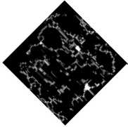
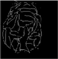
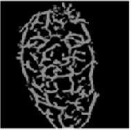
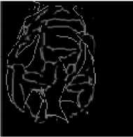
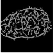
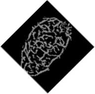
Face veins based identification is an advanced technique which is used for personal identification. In the face veins based techniques, the thermal image of a person is taken with the help of IR camera [3] [9]. Only IR cameras are eligible for showing the structures of face veins and blood vessels that carry the warm blood in all body parts, and it is the ultimate reason due to which the human skin is warm in nature. It is observed that every person has unique face veins structure and it helps in identifying a person. Superficial and filtration methods are used for getting the face veins images and the diameter of a face vein is 10 to 15 micro meters [33]. The face veins are affected by the impact of temperature and mental tension because the circulation of blood is dependent on the blood vessels. The veins start changing its structure and size if the temperature of body increases. Due to the expansion in veins, tension is generated. Due to tension, the diameter of veins is reduced, and it has very high impact on the circulatory system. The sample of actual image, thermal image, face veins image and thinned face veins patterns is represented by fig. 1 [13].
In this paper we have presented a new technique for identifying a person using face veins patterns. The proposed technique is using some important steps like extracting face veins from thermal image; thinning face veins; constructing minutiae graph (MG) from the thinned face veins image; finding minimum cost minutiae tree (MCMT); traversing MCMT and matching the results.
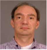
1(a) Actual image
1(b) Thermal image
1(c) Face veins image 1(d) Thinned image
Fig. 1. Sample of actual image, thermal image, face veins image and thinned face veins [13]
In the next section II we have described and reviewed the literature of research papers published on the topic related to face veins based personal identification. In section III we have developed mathematical model for describing the structure of our proposed technique. In the section IV we have proposed a new method for identifying a person using face veins features. The proposed method is converted in the form of algorithms in this section. In section V, we have analyzed the performance of our proposed algorithm and the results of proposed technique are compared with other existing techniques for standard (Terrivic Dataset) and self generated datasets [28]. In section VI, the conclusion and future research directions are presented.
-
II. Literature Review
Mottl Vadim et al. used elastic transformation method for identifying the unique face of a person on the basis of two pixel grid [22]. Shiguang Shan et al. proposed Face Specific Subspace based approach to identify the unique faces of persons. The comparison of results was done by using Yale Face Database. In this approach 350 subjects were used for robustness testing [31]. Leonardo Trujillo et al. has used local and global feature extraction based approach to solve the problems of face recognition. They have used Support Vector Machine based algorithm for the classification of face [33]. Marc Garbey et al. used fast Fourier transformation based method for detecting the face and he used the pulse rate for measuring the temperature of vessels on the basis of blood flow [9]. Gang Wang Jian et al. have used infrared images for extracting the features of a person’s face. They used face detection and feature extraction method for analyzing the face veins of a person [35].
Buddharaju Pradeep et al. used thermal image for extracting the vessels and blood perfusion for showing the face veins just like a finger veins with the help of facial vasculature structure [3]. Arandjelovic Ognegen et al. proposed a technique in which they first took visual images and then took thermal images and these images were compared with the help of principle of angle and data processing [2]. Chennamma et al. proposed a MRF model for human face recognition. The use of MRF model involves drawing a sketch image and matches it to the photo image [6].
Martinez Brais et al. identified the human face through thermal images and they compared eyes, nose and mouth of other human faces with the help of Haar Wavelet Decomposition (HWD) method [19]. Mekyska Jiri et al. proposed thermal face segmentation method for segmenting the thermal images. The coordinates of these segmented thermal images were taken for identifying persons [20]. The LWIR camera was used by Gault Travis et al. for capturing a thermal image. The vessels selection, pulse measurement and wavelet transformation were used for multi-resolution analysis of thermal images [10].
Chen Cunjian et al. used the thermal images and NIR images of human faces for identifying the gender with the help of LBHP method. Here, PCA and GMM model were used for gender identification of human faces and the method can successfully recognize the gender of a person through face [5]. Cho Siu Yeung et al. developed TIFA, Fuzzy CMAC and Neural Network based model for detecting unique person through face veins [7]. The proposed method identifies a person accurately. Hartung Daniel et al. used hand veins and finger veins for identifying a person. He designed and developed BVPR system which uses spectral minutiae patterns for solving the problem of personal identification [14] [15].
Guzman Ana et al. developed a method in which a thermal image is registered with the help of FLIRT technique. The feature extraction, noise removal, image morphology and thermal facial signature were applied on the registered image for identity verification [12]. Seal Ayan et al. used LBP and HWT based approach for identifying a person uniquely. In this method the researchers described that the thermal image is converted into gray scale image and the gray scale image is converted into binary image. The binary image is compared with other images for identity verification [27] [28] [26]. The thermal face recognition system developed by [27] [28] has two parts; image processing and classification. The researchers Seal Ayan et al. performed minutiae points based activities to compare the face veins of two persons [27] [28]. Here, TFRS based technique was used by [30] to compute the minutiae points from the thermal image.
Chekmenev Sergey et al. used the superficial temporal artery methods for measuring the arterial pulse and they used multi-resolution wavelet based signal analysis methods for extracting arterial pulse wave [4]. Kuratate Takaaki et al. used 3D appearance image for generation identification. The 3D appearance image is also used in robot navigation, object identification and human robot interaction. Here, mask-bot was used to identify the gender of humanoid robotics face [17]. Wong Wai et al. have used head curve geometry method for extracting the images from thermal face [36]. Osia Nnamdi et al. used MWIR technique for taking thermal images. In this proposed method fiducial points are used to compare multiple faces with the help of SIFT technique [25].
Guzman et al. used MWIR camera for the collection of thermal images. They used feature extraction method and FLIRT technique for the processing of registered image. The method proposed by Guzman et al. identifies a person correctly [13]. Wang Ning et al. used Multibiometric system in which multiple faces are compared with each other by taking the help of complex fusion method [34].
Amirthavalli et al. obtained a thermal image with the help of thermal vision camera and they used image morphology based thermal signature extraction technique for identifying individuals [1]. Negied Nermin et al. used the infrared spectrum based thermal band technique to identify a person. Here, vasculature temperatures of face veins play an important role in differentiating individuals [23]. Ghiassa Reza et al. used SWIR, MWIR, LWIR, and IR camera for taking a thermal image. These thermal images were used for obtaining the face veins of human. The LBP, Wavelet Transform and neural network based processing and matching techniques were used by Ghiassa Reza et al. to identify a person [11].
Kumar Sanjith et al. used MWIR technique for the collection of thermal images. They used Gabor filter before registering the image and took one reference image for matching with all other images [16]. Lavanya et al. used thermal image for representing the vasculature and blood perfusion. The vasculature emits heat due to the flow of blood via veins. These blood veins are used for comparing the facial structures of two images of the same persons or different persons [18]. Nithyakalyani et al. proposed human biometric system for identifying a person uniquely on the basis of facial feature [24].
-
III. Mathematical Structure Of Proposed Technique
Let ‘U’ is a universal set which contains values of edges of five different sets for a person. It is represented with {‘A’, ‘B’, ‘C’, ‘D’, ‘E’} and each set contains the pairing values of edges and vertices. The minutiae points of face veins graph are represented by vertices (‘v’) and edges connecting these minutiae points are represented by ‘e’. The pairing values of {‘u’, ‘e’ and ‘v’} are stored in each set where, ‘u’ represents starting of vertices, ‘e’ represents edge length between vertices and ‘v’ represents ending of vertices of face veins graph.
A= {(u 1 , e 1 , v 1 ), (u 2 , e 2 , v 2 ) … (u n , e n , v n )}
B= {(u1, e1, v1), (u2, e2, v2) ... (un, en, vn
C= {(u1, e1, v1), (u2, e2, v2) ... (un, en, vn
D= {(u1, e1, v1), (u2, e2, v2)… (un, en, vn
E= {(u1, e1, v1), (u2, e2, v2)… (un, en,v
U= {A U B U C U D U E}(1)
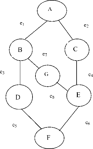
Fig. 2. Graphical representation of minutiae graph of person.
Definition of Minutiae Graph
The vertices (‘v’) and edges (‘e’) of a face veins image are represented in the form of graph called as Minutiae Graph (MG). A minutiae graph (MG) has many spanning trees; but one and only one amongst them will be the Minimum Cost Minutiae Tree (MCMT).
Definition of Minutiae Tree
A spanning tree of a minutiae graph will be called as Minutiae Tree (MT). A minutiae tree will be generated from MG and it will include all the vertices of MG but no circuit will be formed in the MG.
The minutiae graph and the corresponding minutiae tree for face veins of a person can be represented by figures 2 and 3 respectively.
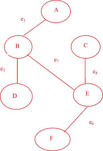
Fig. 3. Graphical representation of a minutiae tree for figure 2.
Theorem 1: For every person’s face veins pattern there exist at least one minutiae tree.
Proof: Human face veins structure is similar to vertices and edges of fig. 2, where every face vein is connected with points and these points are called minutiae points or vertices. The veins connecting minutiae points are called as edges.
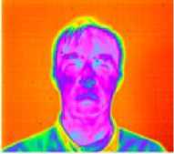
Let us consider another graph of fig 4, where minutiae points and connecting veins of face veins patterns are represented by vertices and edges. In fig. 4 minutiae points are represented with vertex {‘A’, ‘B’, ‘C’, ‘D’, ‘E’, ‘F’, ‘G’} and connecting veins are represented with edges {‘e1’, ‘e2’, ‘e3’, ‘e4’, ‘e5’, ‘e6’, ‘e7’, ‘e8’, ‘e9’, ‘e10’, ‘e11’, ‘e12’}.
With the help of fig.4, we can say that blood is circulating in veins and hence the veins are connected with each other. These connected veins are forming a minutiae graph. Since, every minutiae graph has at least one spanning tree. Therefore, the connected graph (minutiae graph) of fig. 4 has at least one spanning tree.
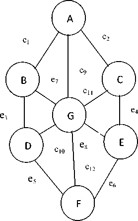
Fig. 4. Graphical representation of minutiae graph
Every person’s face veins are connected and are forming a minutiae graph (MG). Every MG has a spanning tree. The spanning tree of a MG is called as minutiae tree (MT). Therefore, we can say that every person’s face veins pattern will have at least one MT.
Hence, theorem 1 is proved.
Theorem 2: For a MG there exists one and only one Minimum Cost Minutiae Tree (MCMT).
Proof: Let ‘US’ is a universal set that contains the pair of vertices & edge values of a MG. Let us take another set {‘W’, ‘X’, ‘Y’, ‘Z’} which represents different cost minutiae trees and it contains minimum edge values of the graph. The set ‘US’ can be mathematically represented by Eq. (2).
US = {(V 1 , E 1 ), ( V 2 ,E 2 ), ..(V n , E n )} (2)
We can generate different spanning trees from Eq.(2) and the paths of these spanning trees can be represented by Eq. (3), Eq. (4), Eq. (5) and Eq. (6).
|
W = {P 2 , P 4 , P 6 ,… |
.. P2n} |
(3) |
|
X = {P 1 , P 3 , P 5 ,.. |
..P 2n-1 } |
(4) |
|
Y = {P 1 , P 4 , P 7 ,… |
.. P 3n-2 } |
(5) |
|
Z = {P2, P6, P10,… |
.. P4n-2) |
(6) |
In Eq.(3) to Eq.(6), P1, P2, ..Pn are representing different paths of spanning trees and ‘W’, ‘X;, ‘Y’, ‘Z’ are representing different cost MCMTs. The Eq. (7) to Eq. (10) is used to calculate the edge values of every minimum cost spanning tree (MCST).
Since, we select the minimum cost edges for constructing the minimum cost spanning tree in Kruskal’s method. Therefore, the paths generated in Eq.(3), Eq.(4), Eq.(5) and Eq.(6) will be exactly same and Eq.(7) to Eq.(10) will return the same numeric values for path traversal.
Since, Prim’s and Kruskal’s method generate the same minimum cost spanning tree (MCST) and the MCST for a MG is called MCMT. Therefore, we can say that one and only one MCMT exists for a MG.
Hence, the theorem is proved.
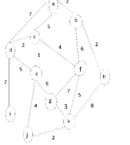
The complex form of MG for the face veins patterns can be represented by fig. 5. In the fig. 5, each vertex is representing a minutiae point and these minutiae points are connected with each other through edges. The number of pixels between two minutiae points is representing the edge length.
The Eq. (11) is used for calculating the cost of minutiae graph.
Cost of MG (CMG) = ∑7=1 et (11)
Where, n represents total number of edges in the MG and ∀ MG, ( Ui + Ui < n). Hence, for every MG the number of vertices will always be less than the number of edges.
Let us define the variables which are used for representing our proposed algorithm for face veins based personal identification. These variables are: MT: Minutiae Tree, m: Number of edges in MT, n: Number of edges in MG, p: Number of vertices in MT, q: Number of vertices in MG, V i : Total number of vertices in MT, RT: Root vertices in MT, L i : Left vertices of a vertex in MT, R i : Right vertices of a vertex in MT, e i : Number of edges in MT, tmp: Total number of minutiae points in a MT, mp: Minutiae points in MT, G: Total number of edges
|
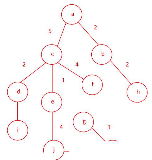
and vertices of a MT, MCMTT: Minimum cost minutiae tree traversal, and tsmcmt: Total size of MCMT. 7 a 2 b 5 c 22 d 4 6 1 5 f e h 7 6 7 5 g i 4 3 8 k j 2 Fig. 5. Graphical representation of complex face veins pattern for a person. The minutiae points and its edge values for a face veins pattern are represented in the fig. 5, where ‘a’, ‘b’, ‘c’, ‘d’, ‘e’, ‘f’, ‘g’, ‘h’, ‘i’, ‘j’ and ‘k’ are representing the minutiae points. The numeric values of fig. 5 represent the number of pixels between minutiae points of face veins image. We can use Kruskal’s or Prim’s algorithm to find the MCMT for a MG. The MCMT of fig. 5 is represented by fig. 6. The fig. 6 is obtained after applying the steps of Kruskal’s algorithm on fig. 5. The MCMT of fig. 6 can be traversed in pre-order to obtain the string which will be used in the smartcard for identity verification. The Eq. (12) represents the total number of minutiae points of the minimum cost minutiae tree. tmp = Z= (RTt , Lb R) (12) The cost of a minutiae tree is represented by Eq. (13). CMT= Z™ ( 6 ; (13) In Eq. (13), CMT is representing the cost of minutiae tree, and ‘m’ < ‘n’ where ‘m’ is representing number of edges and ‘n’ is representing number of vertices in a MT. The Eq. (14) will represent the calculation of edge values with vertices after completing the traversal process. G= ZZ ZT= 1 vi [R Tj , j R]6 (14) We have already proved that the MCMT obtained in fig. 6 is unique for every person’s face veins patterns. The Prim’s algorithm which is used for finding minimum cost spanning tree can be represented in Eq. (15). |
M= {(n, P[n]): n C N-{x} -Q} (15) In Eq.(15), ‘M’ is a set that contains minimum cost minutiae values, P[n] is representing the parent vertices, {x} represents root vertices and {Q} represents the sequence of traversing the vertices and edges of a MCMT. If a MCMT has no vertices and edges then the value will be zero and the algorithm will be terminated. The termination condition for our proposed algorithm is represented by Eq. (16). M= {(n, P[n]): n e N- {x}} (16) The total cost of pre-order traversal for vertices and edges of a MCMT can be represented by Eq. (17). tc = Z7= i e / (n) (17) a 5 2 c b 2 4 2 1 f d h e 7 g i 4 3 j k 2 Fig. 6. Graphical representation of minimum cost spanning tree Finally, on the basis of these mathematical derivations and equations we conclude that every person has unique MCMT traversal and this string will stored in database repository for identifying a person. IV. The Proposed Technique The minimum cost minutiae tree based thermal face identification is proposed in this section. The proposed technique uses following steps for processing thermal face image of a person: Step I: Extract face veins from thermal image of a person. Step II: Finding minutiae points from the face veins pattern. Step III: Construct minutiae graph from minutiae points which includes breakage patterns also. Step IV: Find minimum cost minutiae tree for the minutiae graph of a person. |

Step V: Traverse the minimum cost minutiae tree in pre-order/post-order/in-order.
Step VI: Use the vertices and edges of traversed MCMT to obtain the string which will be used for identifying a person.
-
A. Extracting Face Veins from Thermal Image
After selecting the thermal image, we have proceeded to extract the features of thermal images. The face veins extraction uses following steps for finding the face veins image of a person:
Step I: Face Segmentation (In this step thermal images will be processed and segmented.)
Step II: Noise Removal (After completing the face segmentation process the noise removal process will be used to remove noise disturbances like hair, neck, and ear. The Perona-Malik-Anistropic filter is used for noise removal [13].)
Step III: Image Morphology (After completing the noise removal, we will use image morphology process.)
Step IV: Post Processing (Here, skeletonization process is used to reduce the foreground region.)
Step V: Generation of Face veins Image (Here, the face veins pattern is obtained. This step is important for finding minutiae points.)
-
B. Finding Minutiae points from Face Veins Patterns of a Person
In a minutiae graph the minutiae points are represented by vertices of graph and the number of pixels between two adjacent minutiae points are represented by edge length of the graph. The approach used for obtaining minutiae points from face veins pattern uses thirty two situations. These situations are used to get the vertices of a minutiae graph which will be drawn from the face veins patterns. The cases used to obtain minutiae points from the face veins patterns are presented in figure 7.
The minutiae points are obtained after using cases from m1 to m24 of fig. 7 and the breakage points or end vertices are obtained from the cases m25 to m32 of the same figure.
m1 = [0,0,1;1,1,0;0,0,1];
m3 = [1,0,0;0,1,1;1,0,0];
m5 = [1,0,0;0,1,1;0,1,0];
m7 = [0,1,0;1,1,0;0,0,1];
m9 = [0,0,0;1,1,1;0,1,0];
m11 = [0,1,0;1,1,1;0,0,0];
m13 = [1,0,1;0,1,0;1,0,0];
m15 = [0,0,1;0,1,0;1,0,1];
m17 = [0,1,0;1,1,1;1,0,0];
m19 = [1,0,0;1,1,1;0,1,0];
m21 = [0,1,0;0,1,1;1,1,0];
m23 = [0,1,1;1,1,0;0,1,0];
m25 = [1,0,0;0,1,0;0,0,0];
m27 = [0,0,1;0,1,0;0,0,0];
m29 = [0,0,0;0,1,0;0,0,1];
m2 = [0,1,0;0,1,0;1,0,1];
m4 = [1,0,1;0,1,0;0,1,0];
m6 = [0,0,1;1,1,0;0,1,0];
m8 = [0,1,0;0,1,1;1,0,0];
m10 = [0,1,0;1,1,0;0,1,0];
m12 = [0,1,0;0,1,1;0,1,0]
m14 = [1,0,1;0,1,0;0,0,1];
m16 = [1,0,0;0,1,0;1,0,1];
m18 = [0,1,0;1,1,1;0,0,1];
m20 = [0,0,1;1,1,1;0,1,0];
m22 = [1,1,0;0,1,1;0,1,0];
m24 = [0,1,0;1,1,0;0,1,1];
m26 = [0,1,0;0,1,0;0,0,0];
m28 = [0,0,0;0,1,1;0,0,0];
m30 = [0,0,0;0,1,0;0,1,0];
m31 = [0,0,0;0,1,0;1,0,0]; m32 = [0,0,0;1,1,0;0,0,0];
Fig. 7. The cases used for extracting minutiae points from face veins [21] [32].
-
C. Finding Minimum Cost Minutiae Tree (MCMT) from Minutiae Graph
The adjacent minutiae points obtained after applying the conditions of fig. 7 are joined together to obtain the minutiae graph. Now, the minutiae graph will be given as input to construct the Minimum Cost Minutiae Tree (MCMT).
The algorithm for constructing MCMT from a minutiae graph is presented in fig. 8.
Input: Minutiae Graph
Output: Minimum Cost Minutiae Tree
-
1. Algorithm Minimum_Cost_MT(minutiae graph ) {// assume that g has at least one vertex
-
2. mpv={0}; // start with vertex 0 and no edge
-
3. for (t=0; t contain fewer than e-1edge; add (ui, vi) to t) {
-
4. Let (ui,vi) be a minimum cost edge such that ui is the element of mpv and v i is not the element of mpv;
-
5. If (there is no edge) break;
-
6. { Add v i to mpv;}
-
7. if (t contains fewer than e-1 edge)
-
8. { printf (“ minutiae point”;}
} // End of for loop
} // End of algorithm
-
Fig. 8. Algorithm for finding Minimum Cost Minutiae Tree
In fig. 8, ‘ g’ represents at least one vertex of the minutiae graph, ‘t’ represents number of vertices in minutiae graph, ‘u i ’ represents starting vertex, ‘v i ’ represents end vertex and ‘e i ’ represents edge of vertices.
-
D. Constructing Identification String from MCMT
We can traverse the MCMT in pre-order/ post-order/ in-order to get the identification string. But, in our research work we have used the pre-order traversal based approach for constructing the identification string because the pre-order traversal takes minimum time in comparison to other traversal algorithms.
The identification string will consist of vertices and edge lengths of MCMT. The algorithm used for finding vertices and edges of traversed string from MCMT is presented in fig. 9.
Input: Minimum Cost Minutiae Tree.
Output: Traversal string of vertices and edges.
-
1. Algorithm Minutiae_Tree_Traversing_Procedure (minutiae tree)
-
2. preorder(r);
-
3. preorder(MTNode *CurrentNode)
// the traversal preorder traverse the { if (CurrentNode)
-
4. {printf (CurrentNode -> data);
-
5. preorder (CurrentNode -> leftChild);
-
6. preorder (CurrentNode -> rightChild);
{ // Traversal process of Minutiae Tree
}} }
-
Fig. 9. Traversal of Minimum cost minutiae tree
In fig. 9, ‘ r’ represents root vertex of minutiae tree, The ‘ CurrentNode’ represents selected minutiae points of MCMT and ‘l eftChild’ represents the left side vertices of MCMT, ‘r ightChild’ represents the right side vertices of MCMT. Each person will have a unique MCMT preorder traversal value called “ identification string” and this string will be used in the smart card memory for further identification.
(I )Actual image (ii) 900 right rotation
V. Experimental Results and Analysis
To analyze the performance of our proposed technique we need to execute the following steps:
Step1: Collection of Face veins Image.
Step 2: Make Minutiae Graph.
Step 3: Find Minimum Cost Minutiae Tree.
Step 4: Result Comparison.
These steps are presented in the sub sections A, B, C and D in section five of this paper. More over the sub sections E, F and G are presenting the detailed analysis of results and the comparison of proposed technique with other standard techniques is also discussed.
(iii) 1800 right rotation (iv) 2700 right rotation
(i) Actual image

(ii) 900 right rotation
(v) 900 left rotation (vi) 1800 left rotation
(iii) 1800right rotation
(vii) 2700 left rotation (viii) 3150 left rotation
10(b) Face veins image of second person at different angle rotation
(v) 900 left rotation
(iv) 2700 right rotation

(vi) 1800 left rotation
(i) Actual Image (ii) 900 right rotation
(vii) 2700 left rotation
(viii) 3150 left rotation

(iii) 1800 right rotation (iv) 2700 right rotation
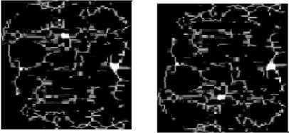
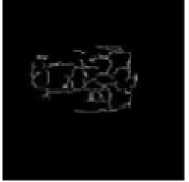
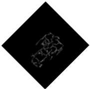
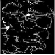
10(a) Face veins image of first person at different angle rotation
(v) 900 left rotation
(vi) 1800 left rotation
(i) Actual image
(ii) 900 right rotation
(vii) 2700 Left rotation
(viii) 3150 left rotation
(iii) 1800 right rotation

(iv) 2700 right rotation
10(c) Face veins image of third person at different rotation angles
(i) Actual Image

(ii) 900 right rotation

(v) 900 left rotation
(vi) 1800 left rotation
(iii) 1800 right rotation

(iv) 2700 right rotation

(vii) 2700 left rotation
(viii) 3150 left rotation
10 (e) Face veins image of fifth person at different angle rotation
(v) 900 left rotation
(vi) 1800 left rotation
(vii) 2700 left rotation
(viii) 3150 left rotation
10(d) Face veins image of fourth person at different rotation angles
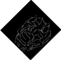
Fig. 10. Face veins images of five persons at different angles of rotations
-
A. Collection of Face Veins Image
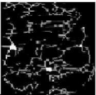
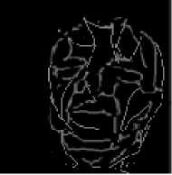
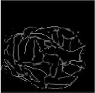
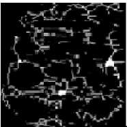
In this step the Infra-Red (IR) camera is used for taking thermal images. Perona-Malik-Anistropic filter is used for finding the face veins image [13]. We have taken eight face veins images of the same person at different angle rotations for the experimentation purpose; total five person’s images are stored in our own data set. The dimensions of each image must be 120×120. These images are represented in figures 10(a), 10(b), 10(c), 10(d) and 10(e).
-
B. Generating Minutiae Graph from Face Veins Patterns
After finding the face veins image, a MATLAB program is used for generating minutiae graph. In our experiment we performed operation on image whose size must be 120 x 120 pixels. The steps used to generate minutiae graph from face veins patterns of a person are as follows:
Step 1: Thinned the image.
Step 2: Found the minutiae points.
Step 3: Generated line graph.
The detailed description of these steps (step 1 to step 3 ) is presented in following three parts:
-
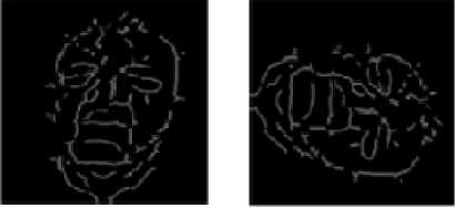
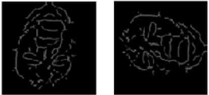
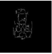
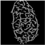
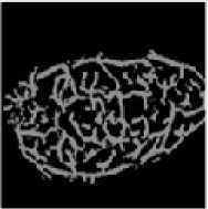
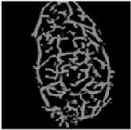
(i) Thinned Images of Different Persons for the Face
Veins Patterns
The face veins image is converted into binary image (Black &White) using im2bw(image, level) MATLAB function and then the bwmorph(image, ’option’, level) function is used to generate the thinned images shown in fig. 11.
Bifurcation point Trifurcation point
11(a) Thinned face veins image for person_1
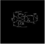
Trifurcation points Bifurcation points
11(b) Thinned face veins image for person_2
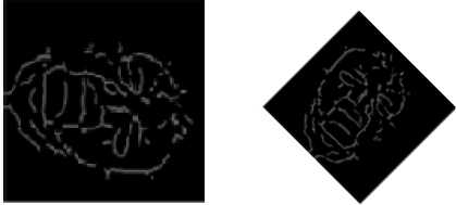
Bifurcation points Trifurcation points
11(c) Thinned face veins image for person_3
Trifurcation points Trifurcation points 11(d) Thinned face veins image for person_4
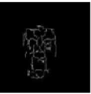
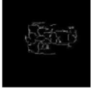
Bifurcation points Trifurcation points
11(e) Thinned face veins image for person_5
Fig. 11. Thinned image of different persons based on face veins patterns
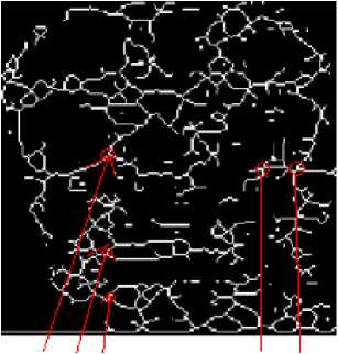
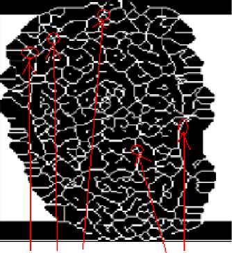
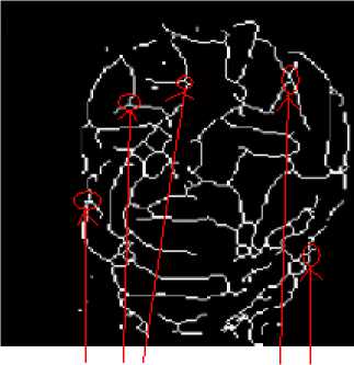
The thinned images of fig. 11 show that each thinned image has bifurcation / trifurcation points and breakage points. The bifurcation / trifurcation points of face veins patterns will be considered as the minutiae points. The MCMT can be obtained from a minutiae graph of face veins patterns.
If we use either Kruskal’s or Prim’s algorithm for finding MCMT from a minutiae graph then same MCMT is obtained for all the rotations of a minutiae graph. Therefore, rotated face veins images at different angles of a person for fig. 11 will result in the same MCMT. Hence, we have taken the first face veins image of each person from fig. 11 for further processing.
-
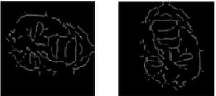
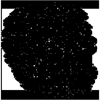
(ii) Finding Minutiae Points from the Thinned Image
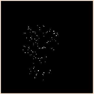
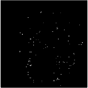
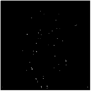
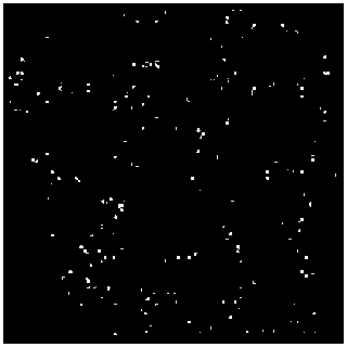
We have performed clean(), close(), majority(), branchpoints(), and shrink() functions on the thinned image of fig. 11 to get the minutiae points of fig. 12. After analyzing the minutiae points of fig 12, it is observed that each face veins pattern has approximately 80 to 200 minutiae points. The minutiae points of fig. 12 show that each person’s face veins pattern has a unique set of minutiae points.
12(a) Vertices of minutiae graph for person_1
12(e) Vertices of minutiae graph for person_5
Fig. 12. Vertices of minutiae graph of different persons
12(b) Vertices of minutiae graph for person_2
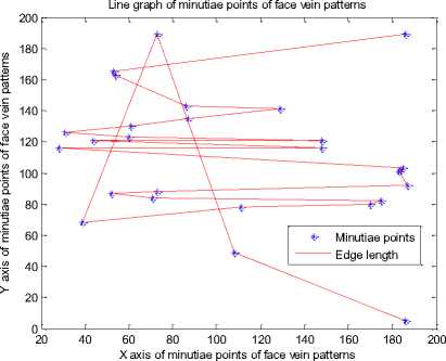
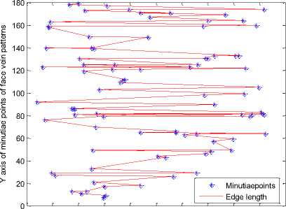
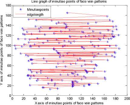
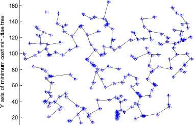
(iii)Generating Line Graphs from Minutiae Points
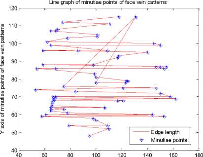
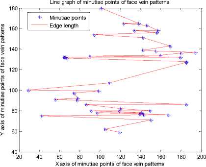
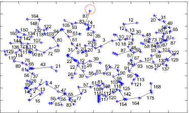
After generating minutiae points for a thinned face veins image we can generate a line graph by connecting the minutiae points. The MATLAB function sparse (image) is used to find the coordinates of each minutia point and plot(X coordinate, Y coordinate) function is used generate the line graph. The line graph generated for each person’s minutiae points of figure 12 is presented in fig. 13.
After analyzing the line graphs of fig. 13 we can say that each person’s face veins have a unique line graph. The line graphs of every person’s face veins pattern is completely different from other persons.
12(c) Vertices of minutiae graph for person_3
X axis of minutiae points of face vein patterns
13 (a) Line graph of person_1
12(d) Vertices of minutiae graph for person_4
13(b) Line graph of person_2
Line graph of minutiae points of face vein patterns
0 20 40 60 80 100 120 140 160 180 200
X axis of minutiae points of face vein patterns
13 (c) Line graph ofperson_3
13 (d) Line graph of person_4
13 (e) Line graph of person_5
Fig. 13. Line graph of different persons
The results of figure 13 show that each person is having a unique line graph which is obtained by connecting the nearest minutiae points with each other. The minutiae graph of figure 12 and the line graph of figure 13 are useful for constructing the MCMT.
-
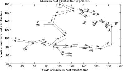
C. Generating the MCMT from Minutiae Graph
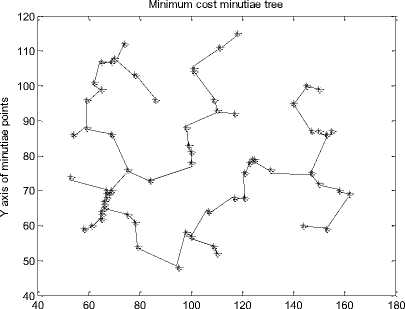
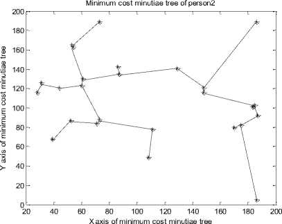
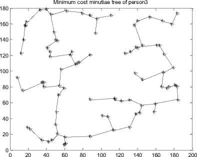
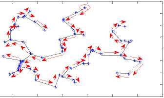
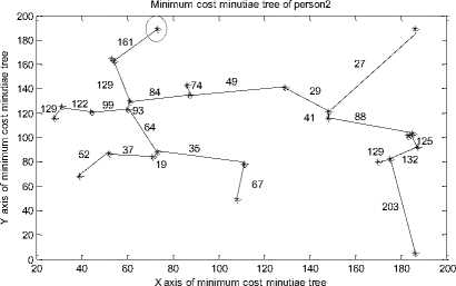
The nearest minutiae points are connected with each other with the help of line() function of MATLAB to construct minimum cost minutiae tree. The MCMTs for minutiae points of fig. 12 are presented in fig. 14.
After analyzing the results of fig. 14 it is observed that each person has a unique MCMT and for different face veins of the same person we get the MCMT. The MCMTs of fig. 14 can be traversed in pre-order / postorder / in-order to obtain the final string which may be used for further identification of a person.
X axis of minutiae points
14(a) MCMT for person_1
14(b) MCMT for person_2
X axis of minimum cost minutiae tree
14(c) MCMT for person_3
Minimum cost minutiae tree
40 60 80 100 120 140 160 180
X axis of minutiae points
15(a) Pre-order traversal string for MCMT of person_1
Minimum cost minutiae tree of person 4 180
0 20 40 60 80 100 120 140 160 180 200
X axis of minimum cost minutiae tree
14(d) MCMT for person_4
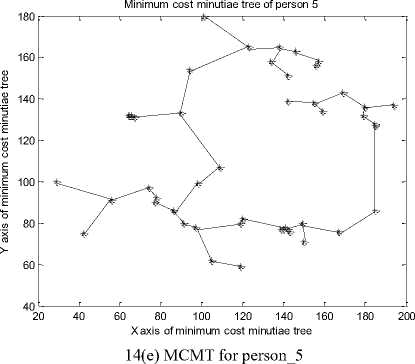
Fig. 14. Minimum Cost Minutiae Tree for Different Persons
15(b) Pre-order traversal string for MCMT of person_2
Minimum cost minutiae tree of person3
0 20 40 60 80 100 120 140 160 180 200
X axis of minimum cost minutiae tree
15(c) Pre-order traversal string for MCMT of person_3
-
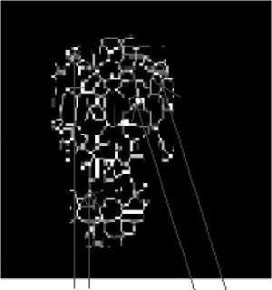
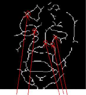
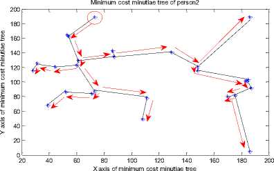
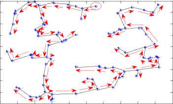
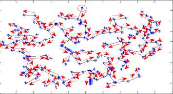
D. Traversal of MCMT and Comparing the Results
We have used pre-order traversal for traversing the MCMT which is given in Fig.15. A vertex is selected as the start vertex. The arrows of figure 15 show the direction and sequence of vertices which we have traversed and the traversal results are shown by arrow in fig. 15.
The top vertex from the upper port of the tree is selected as the start vertex. The start vertex is marked as a circle in fig. 15. While traversing a MCMT in pre-order we include vertices and edge lengths to form the string.
The pre-order traversal for MCMT of fig. 15 will use following g three steps:
Step I: Traverse the root vertex in pre-order.
Step II: Traverse the left edge and the left node in preorder.
Step III: Traverse the right edge and right node of MCMT in pre-order.
Step IV: Repeat the steps from step I to step III until all the vertices and edges are not traversed.
Minimum cost minutiae tree of person 4
0 20 40 60 80 100 120 140 160 180 200
X axis of minimum cost minutiae tree
15(d) Pre-order traversal string for MCMT of person_4
15(e) Pre-order traversal string for MCMT of person_5
Fig. 15. Pre-order traversal strings for minimum cost minutiae trees of different persons
The pre-order traversal and the corresponding graphical representation of fig. 15 show that each person’s face veins has a unique structure for pre-order traversal of MCMTs.
-
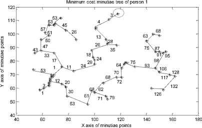
E. Generating String Code for MCMT
After completing the traversal process we have generated a string code for MCMT to compare the face veins pattern of one person with another person. It is observed and found in the experiments that each person has a unique string code values. Before generating the string code values we need to find edge length between vertices.
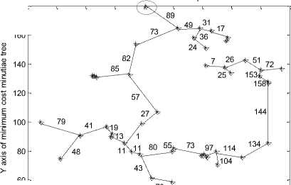
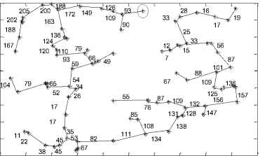
The vertices and the corresponding edge length values for MCMTs of figure 15 are presented in figure 16. The red circled vertices of fig. 16 show the start vertices. These start vertices will be used for pre-order traversal and these vertices will be useful constructing the MCMT traversal string.
16 (a) String code of MCMT for person_1
Minimum cost minutiae tree of person 4
0 20 40 60 80 100 120 140 160 180 200
X axis of minimum cost minutiae tree
16 (d) String code of MCMT for person_4
Minimum cost minutiae tree of person 5
20 40 60 80 100 120 140 160 180 200
X axis of minimum cost minutiae tree
16 (e) String code of MCMT for person_5
Fig. 16. Strings code of minimum cost minutiae trees of different persons.
16 (b) String code of MCMT for person_2
Minimum cost minutiae tree of person 3
0 20 40 60 80 100 120 140 160 180 200
X axis of minimum cost minutiae tree
16(c) String code of MCMT for person_3
In the figure 16, if the number of vertices in a MCMT is ‘n’ then the number of edges will be ‘n-1’. The value of ‘n’ plays an important role in the compression of face veins pattern of a person.
F. Comparison of Different Persons Using String Code
In this phase we compare the pre-ordered traversed vertices and edge length values (string) of one person with another person. We deviated the edge length values from -5 to +5 in a simulated environment for robustness testing. Further, we observed that if the deviation of edge length values for a person is below -5 or above +5 then the matching results decrease abruptly. If the string values of two persons have match percentage above 80% and above then it means that both the strings for the face veins pattern are belonging to the same person. In other cases where the match percentage is below 80% then we assume that face veins strings are belonging to different persons.
In our experiments we observed that match percentage of face veins MCMT traversal strings for two different persons is below 30% and for the same person it is above 80%. The vertices and edge lengths for pre-order traversal of MCMTs are presented in fig. 17.
P1={(1,3), (2,4), (3,13), (4,28), (5,26), (6,18), (7,24), (8,29), (9,24), (10,11), (11,17), (12,33), (13,47), (14,50), (15,51), (16,57), (17,53), (18,45), (19,26), (20,53), (21,43), (22,53),(23,3), (24,1), (25,12), (26,20), (27,30), (28,53), (29,61), (30,68), (31,71), (32,79), (33,62),
(34,68), (35,72), (36,70), (37,64), (38,75), (39,93),
(40,106), (41,117), (42,128), (43,132), (44,126), (45,98),
(46,95), (47,91), (48,87), (49,75), (50,63), (51,68),
(52,35)}
17(a) Vertices and edge length values of MCMT traversal for person_1
P2={(1,161,), (2,129), (3,93), (4,99), (5,122), (6,129), (7,64), (8,19), (9,37), (10,52), (11,35), (12,67), (13,84), (14,49), (15,29), (16,41), (17,88), (18,125), (19,32),
(20,129), (21,203), (22,27), (23,74)}
17(b) Vertices and edge length values of MCMT traversal for person_2
P3={(1,93), (2,109), (3,126), (4,149), (5,172), (6,188), (7,200),(8,250), (9,202), (10,188), (11,170), (12,163),
(13,136), (14,124), (15,120), (16,110), (17,93), (18,66), (19,59),(20,54), (21,52), (22,65),(23,79), (24,104),
-
(25,34), (26,26),(27,17), (28,17), (29,35), (30,45), (31,45), (32,38), (33,22),(34,11), (35,53), (36,67), (37,82),
-
(38,111), (39,134), (40,138), (41,131), (42,128), (43,132), (44,117), (45,156), (46,157), (47,136), (48,125), (49,109), (50.101), (51,87), (52,56), (53,33), (54,25), (55,33),
-
(56,28), (57,16), (58,17), (59,19), (60,15), (61,12), (62,7), (63,88), (64,67), (65,109), (66,87), (67,76), (68,55),
(69,108), (70,85), (71,49), (72,90)}
17(c) Vertices and edge length values of MCMT traversal for person_3
P4={(1,87), (2,83), (3,93), (4,105), (5,74), (6,71), (7,52), (8,35), (9,20), (10,20), (11,20), (12,3), (13,9), (14,41), (15,61), (16,61), (17,85), (18,94), (19,103), (20,118),
(21,122), (22,132), (23,148), (24,164), (25,80), (26,69), (27,72), (28,81), (29,90), (30,100), (31,112), (32,107), (33,121), (34,136), (35,111), (36,114), (37,119), (38,129), (39,31), (40,22), (41,22), (42,26), (43,10), (44,39),
(45,55), (46,61), (47,63), (48,61), (49,72), (50,90),
(51,95), (52,103), (53,116), (54,120), (55,120), (56,112),
(57,116), (58,117), (59,108), (60,61), (61,57), (62,73), (63,77), (64,74), (65,65), (66,55), (67,55), (68,65),
(69,47), (70,37), (71,4), (72,7), (73,7), (74,2), (75,14), (76,19), (77,26), (78,37), (79,56), (80,61), (81,65),
(82,76), (83,89), (84,43), (85,21), (86,2), (87,13), (88,16), (89,65), (90,83), (91,142), (92,154), (93,164), (94,175), (95,178), (96,168), (97,12), (98,26), (99,39), (100,9),
(101,3), (102,3), (103,10), (104,10), (105,18), (106,28), (107,27), (108,13), (109,12), (110,12), (111,30), (112,48), (113,59), (114,58), (115,73), (116,84), (117,93), (118,99), (119,107), (120,105), (121,93), (122,84), (123,67),
(124,57), (125,48), (126,87), (127,65), (128,91), (129,99), (130,99), (131,113), (132,121), (133,107), (134,122),
(135,129), (136,130), (137,137), (138,137), (139,87),
(140,87), (141,78), (142,59), (143,61), (144,58), (145,49), (146,31), (147,31), (148,20), (149,65), (150,87)}
17(d) Vertices and edge length values of MCMT traversal for person_4
P5={(1,89), (2,73), (3,82), (4,85), (5,57), (6,27), (7,1), (8,13), (9,19), (10,41), (11,79), (12,48), (13,11), (14,11), (15,43), (16,73), (17,80), (18,55), (19,73), (20,97),
(21,104), (22,114), (23,134), (24,144), (25,158), (26,153), (27,51), (28,26), (29,7), (30,25), (31,72), (32,49), (33,36), (34,24), (35,31), (36,17)}
17(e) Vertices and edge length values of MCMT traversal for person_5
Fig.17. Vertices and edge length values of MCMT traversal for different persons
In the figure 17, vertices and edge lengths between two vertices are represented with the help of integer values. In fig. 17, the first integer value represents vertices and second integer value represents edge length. If each integer value of MCMT is occupying two bytes space in memory then the total size of memory occupied the MCMT traversal of a person’s face veins will be calculated using Eq. (19).
Total size of MCMT = [2n 1 +2(n 1 -1)]
⇒ Total size of MCMT= 4n 1 - 2 (18)
In Eq. (18), ‘n 1 ’ represent number of vertices and ‘n 1 -1’ represent number of edge lengths of MCMT. The size of MCMT traversal for face veins image of a person for fig. 17 will be approximately 600 bytes whereas the actual size of face veins image is approximately 16KB. Hence, a face veins image of 16KB is compressed into 600 bytes in our proposed technique.
-
G. Result Comparison of MCMT based Technique with
Other Techniques
We have compared the performance of pre-ordered traversed vertices and edge lengths of MCMTs for different persons in our proposed technique. The performance of our proposed technique with other techniques and the comparison results are presented in tables 1 and 2.
In our experimentation it is observed that the rotation of face veins image does not affect the construction of MCMTs.
The results of table 1 show that our proposed technique is clearly identifying individuals on the basis of MCMT traversal of face veins patterns. Further, the results of table 1 show that the persons are differing in their face veins patterns.
Table 1. String code based comparison of different persons
|
S. No |
Matcher Name |
Algorithm |
Matching Results |
|
1. |
Ayan Seal [29] |
Minutiae points based thermal face recognition |
91% |
|
2. |
Ana M. Guzman [13] |
Euclidean (Skeletonized) |
84% |
|
3. |
Ayan Seal [28] |
HWT and LBP |
89% |
|
4. |
Siu. Yeung Cho [7] |
TSK FCMAC |
88% |
|
5. |
Travis R. Gault [10] |
Vascular mapping & multi-resolution analysis |
93% |
|
6. |
Proposed |
MCMTT |
95% and above |
Table 2. Comparison of proposed algorithm with other algorithms
|
Persons |
P1 |
P2 |
P3 |
P4 |
P5 |
|
P1 |
95% |
30% |
25% |
10% |
20% |
|
P2 |
30% |
95% |
15% |
18% |
23% |
|
P3 |
25% |
25% |
95% |
15% |
24% |
|
P4 |
10% |
18% |
15% |
95% |
20% |
|
P5 |
20% |
23% |
24% |
20% |
95% |
We have compared the performance of our proposed algorithm with other algorithms in table 2. We used standard datasets (like Terrivic Dataset) and self generated fabricated face veins for analyzing the performance of our proposed algorithm [28].
-
VI. Conclusions
In this research work we have presented a noble face veins based MCMT traversal technique for identifying individuals. It is observed in experiments that each person has a unique MCMT leading to a unique string code for the face veins pattern. A person can be identified on the basis of MCMT traversal string of face veins images.
Face veins pattern can also be used for identifying identical twins and fraternal twins. We need to develop and test the new technique for the cases of identical twins identification. We can combine behavioural features of a person such as gate signature, hand writing, and body language with the face veins pattern for further improving the matching results of our proposed technique.
References Face Veins Based MCMT Technique for Personal Identification
- Amirthavalli Kannika, and Kirubha D., “Thermal Imaging as a Biometrics Move Towards Facial Signature Substantiation”, International Journals of Advanced Computational Engineering & Networking, Vol. 2, No. 1, pp.54-58, 2014.
- Arandjelovic Ognjen, Hammoud B. Riad and Cipolla Robberto, “Thermal and Reflectance Based Personal Identification Methodology Under Variable Illumination”, Pattern Recognition, Vol. 43, No. 5, pp. 1801-1813, 2010.
- Buddharaju Pradeep, Pavlidis Loannis and Manohar Chinmay, “Face Recognition Beyond The Visible Spectrum”, Advances in Biometrics, Springer London, pp. 157-180, 2008.
- Chekmenev Sergey Y., Farag Aly A. and Essock Adward A., “Thermal Imaging of the Superficial Temporal Artery: An Arterial Plus Recovery Model” IEEE Conference on Computer Vision and Pattern Recognition, pp. 1-7, 2007.
- Chen Cunjian, and Ross Arun, “Evaluation of Gender Classification Methods on Thermal and Near Infrared Face Image”, Biometric International Conference, IEEE, pp. 1-8, 2011.
- Chennamma H. R., Rangarajan Lalitha, and Veerabhadrappa, “Face Identification From Manipulated Facial Images Using SIFT”, IEEE International Conference on Emerging Trends in Engineering and Technology, pp. 192-195, 2010.
- Cho Siu Yeung, Ting Chan Wai, and Quek Chai, “Thermal Facial Pattern Recognition for Personal Verification Using Fuzzy CMAC Model”, International journal of innovative, Information and Control, Vol. 7, pp. 203-222, 2011.
- Deepamalar M., and Madheswaram M., “An Improved Multimodal Palm Vein Recognition System Using Shape and Texture Features”. International Journal of Computer Theory and Engineering, Vol. 2, pp. 95-101, 2010.
- Garbey Marc, Sun Nanfei, Merla Arcangelo, and Pavlidis Loannis, ”Contact-Free Measurement of Cardiac Plus Based on The Analysis of Thermal Imagery”, Biomedical Engineering, IEEE, Vol. 54, pp. 1418-1426, 2007
- Gault Travis R., Blumenthal Nicholas, FaragAly A., Starr Tom, “Extraction of the Superficial Vasculature, Vital Sign Waveform & Rates Using Thermal Imaging”, Computer Vision and Pattern Recognition Workshops, IEE,pp. 1-8, 2010.
- Ghiassa Reza Shoja, Arandjelovi Ognijen, Bendadaa Abdelhakim, and Maldague Xavier, ”Infrared Face Recognition”, Audio – Video Based Biometrics Person Authentication, Springer Berlin Heidelberg, Vol. 47, pp. 2807-2824, 2014.
- Guzman Ana M., Goryawala Mohammmed, and Adjouadi Malek, “Generating Thermal Signatures Using Thermal Infrared Images”, IEEE International Conference on Emerging Signal Processing Application, pp. 21-24, 2012.
- Guzman Ana M. , Goryawala Mohammed, Wang Jin, Barreto Armando, Andrian Jean, Rishe Naphtali, and Adjouadi Malek, “Thermal Imaging as a Biometrics Approach to Facial Signature Authentication”, Biomedical and Health Informatics, IEEE Journal, Vol. 17, pp.214-222, 2013.
- Hartung Daniel, Olsen Martin Aastrup, XuHaiyun, and Busch Christoph, “Spectral Minutiae for Vein Pattern Recognition”, Biometrics International Joint Conference, IEEE, pp. 1-7, 2011.
- Hartung Daniel, “Vascular Pattern Recognition and its Application in Privacy – Preserving Biometric Online – Banking System”, Ph. D. dissertation, Gjovik University College, 2012.
- Kumar MG Sanjith, and Saravanan D, “A Novel Approach To Face Recognition Based On Thermal Imaging”, International Journal of Engineering Research and Technology, Vol.3, pp. 5-9, 2014.
- KuratateTakaaki, Riley, Marcia, Pierce Brennand, Cheng Gordon, “Gender Identification Bias Induced with Texture Image on a Life Size Retro-Projected Face Screen”, RO-MAN, IEEE International Symposium on Robot and Human Interactive Communication, pp. 43-48,2012.
- Lavanya A, Monika S, Sowmiya M., “Thermal Imaging and Facial Recognition Using Biometric Approach”, IJESC Journal, Vol. 16, pp. 62-69, Jan 2014.
- Martinez Brais, Binefa Xavier, and Pantic Maja, “Facial Component Detection in Thermal Imagery “, Computer and Pattern Recognition Workshops, IEEE, pp. 48-54, 2010.
- Mekyska Jiri, Duro Virginia Espinosa, and Zanuy Marcos Faundez, “Face Segmentation: A comparison Between Visible and Thermal Image”, IEEE International Carnahan Conference on Security Technology, pp.185-189, 2010.
- Mishra Kamta Nath, Srivastava P. C., Agrawal Anupam, Garg Rishu and Singh Ankur, “Minutiae Fusion Based Framework for Thumbprint Identification of Identical Twins”, International Journal of Intelligent Systems and Applications, Vol. 6, No. 1, pp. 84-101, 2014.
- Mottl Vadim, Kopylov Andrey, Kostin Alexey, and Yermakov Alexey, “Elastic Transformation of the Image Pixel Grid for Similarity Based Face Identification”, Pattern recognition, Proceedings, of IEEE International Conference, Vol. 3, pp. 549-552, 2002.
- Negied Nermin K., “Moving Toward Thermal Imaging”, International of Recent technology and Engineering, Vol. 2, pp. 73-77, 2014.
- Nithyakalyani K., and Jayanthi T., “Face Recognition As A Biometrics Approach Using Thermal Images”, International Journal of Advances in Science Engineering and Technology, Vol.2, pp. 93-98, 2014.
- Osia Nnamdi, and Bourlai Thirimachos, “Holistic and Partial Face Recognition in the MWIR Band Using Manual and Automatic Detection of Face Based Features”, Homeland Security, IEEE Conference on Technology, pp. 273-279, 2012.
- Prakash K. N., Prasad K. Satya, “Color Local Binary Patterns for Image Indexing and Retrieval”, International Journal of Intelligent Systems and Applications, vol.6, no.9, pp.68-74, 2014.
- Seal Ayan, Ganguly Suranjan, Bhattacharjee Debotosh, Nasipuri Mita, Basu, and Dipak Kumar, “Minutiae Based Thermal Human Face Recognition Using Label Connected Component Algorithm”, International Conference on Computer Communication, Control and Information Technology, Vol. 4, pp. 604-611, 2012.
- Seal Ayan, Ganguly Suranjan, Bhattacharjee Debotosh, NasipuriMita, Basu, and Dipak Kumar, ”Comparative Study of Human Thermal Face Recognition Based on Haar Wavelet Transformation(HWT) and Local Binary Pattern(LBP)”, Computational Intelligence and Neuroscience , Vol. 17, pp.1-12, 2012 .
- Seal Ayan, Bhattacharjee Debotosh, NasipuriMita, Basu, and Dipak Kumar, “Minutiae Based Thermal Face Recognition using Blood Perfusion Data”, Procedia Technology, Vol. 3, pp. 604-611, 2013.
- Seal Ayan, Ganguly Suranjan, Bhattacharjee Debotosh, Nasipuri Mita, Basu, and Dipak Kumar,“ Automated Thermal Face Recognition Based on Minutiae Extraction”, ACM International Journal of Computational Intelligence Studies, Vol. 2, pp. 133-156, 2013 .
- Shan Shiguang, Gao Wen, and Zhao Debin, “Face Identification From A Single Example Image Based on Face Specific Sub Space”, Acoustics, Speech and Signal Processing, IEEE International Conference, Vol. 2, pp. II(21-25), 2002.
- Srivastava P. C., Agrawal Anupam, Mishra Kamta Nath, Tripathi Vivek and Garg Rishu, “Fingerprints, Iris and DNA Features Based Multi-biometric Systems: A Review”, International Journal of Information Technology and Computer Science, Vol. 5, No. 2, pp. 88-111, 2013.
- Trujillo Leonardo, and Olague Gustavo, Hammoud Riad, Hernandez Benjamin, “Automatic Feature Localization in Thermal Images for Facial Expression Recognition”, Computer Vision and Pattern Recognition Workshops, IEEE Computer Society Conference, Vol. 3, pp. 14-14, 2005.
- Wang Ning, Li Qiong, A. Ahmed, Abd E1-Latif, Peng Jialing, NiuXiamu, “Multi-biometric Complex Fusion for Visible and Thermal Face Images”, International Journal of Signal Processing, Image Processing and Pattern Recognition, Vol.6, pp. 1-16, 2013.
- Wang Jian Gang, Sung Eric, “Facial Feature Extraction in an Infrared Image by Proxy with a Visible Face Image”, Instrumentation and Measurement IEEE Transaction, Vol. 56, pp. 2057-2066, 2007.
- Wong Wai Kit, Hui Joe How, “Face Detection in Thermal Imaging Using Head Curve Geometry”, Image and Signal Processing IEEE International Congress, pp. 881-884, 2012.
