
Methodology of determination of balancing weights mounting places inside spacecraft compartments
Journal: Siberian Aerospace Journal @vestnik-sibsau-en
Section: Aviation and spacecraft engineering
Article in issue: 2 vol.27, 2026.
Free access
The paper presents a methodology for determining the mounting places of balancing weights inside spacecraft compartments, based on the use of a combination of methods of analytical and computational geometry, mathematical programming and computer graphics. The use of balancing weights is necessary to ensure the required position of the center of gravity of the compartment and the product as a whole. When using the methodology, the problems of ensuring a minimum mass of balancing weights and reducing the labor intensity of developing options for their installation are solved to speed up the preparation and approval of design documentation. The balancing weight placement zone is considered as a set of spatial regions free from compartment structural elements and other component parts. To minimize the overall mass of the balancing weights by determining their placement locations on a coordinate grid, the balancing weight placement problem is proposed to be represented as a linear programming problem. For testing, a conical compartment of a product with a spherical bottom was used as an example. It was determined that the balancing weight placement zone should be located near the junction of the bottom and the hull shell. The configuration of the placement zone was identified, taking into account the surrounding structural elements. The coordinates for placing the balancing weights were determined, and their masses were selected. Testing has showed the performance of the proposed methodology and the algorithm based on it. Effective use of the methodology is possible with the availability of a specialized calculation software package.
Short address: https://sciup.org/148333983
IDS: 148333983 | UDC: 629.7.022 | DOI: 10.31772/2712-8970-2026-27-2-276-288
Text of the scientific article Methodology of determination of balancing weights mounting places inside spacecraft compartments
When developing design documentation (DD) for spacecraft, at the conceptual or technical design stage, mass-centering and inertial requirements for the product and permissible deviations from them are determined. Ideally, these requirements should be met through a rational layout of the spacecraft's compartments. In practice, numerous errors (design, computational, manufacturing, metrological, etc.) lead to unacceptable deviations in the mass-centering and inertial characteristics (MCIC) of the product [1; 2]. To eliminate these, partial or complete reconfiguration of the compartments is carried out, and when this is impossible for technical and economic reasons, balancing weights (BW) are used.
Various balancing rigs are used to weigh and balance products and their components [2–11]. During spacecraft testing, they provide data on the actual values of mass, center of mass or center of gravity (COG), and moments of inertia. If unacceptable deviations from MCIC are detected, the layout or arrangement of BW is adjusted according to change notices.
There may be cases where the design documentation does not provide for the installation of a BW. During the working documentation stage, during its development or during prototype testing, the need for a BW may be identified. In such cases, a new design group is added to the working documentation, and technically, the number of BWs must be determined and locations for their installation on the spacecraft must be found. The task of locating payloads under such conditions increases the complexity of the design documentation development. A heuristic solution to this problem does not guarantee the use of the minimum number (mass) of BWs.
The objective of this work is to develop and refine a methodology for determining BW installation locations within spacecraft compartments. The objectives of this work include developing computational mathematical models, identifying sources and methods for processing initial data, developing an algorithm for a software package to be developed in the future, and testing (refining) the methodology using a spacecraft compartment as an example.
The relevance of this research topic, in addition to reducing the labor intensity of design documentation development and minimizing the weight of the BW, is determined by the fact that spacecraft balancing using additional BWs will be carried out on both existing and newly developed products. Therefore, a reliable mathematical apparatus and calculation software package for solving the problem of determining BW installation locations will be in demand for quite a long time.
This paper examines the static balancing of spacecraft. For questions on dynamic balancing of spacecraft, it is recommended to refer to works [2; 3; 5; 7–11]. Although determining the actual values of the maximum permissible coefficient of performance of products using dynamic balancing methods can be more accurate, as noted in [11], for large-sized and outsized products, where BW placement zones can cover large areas and, therefore, hundreds of small payloads of various configurations can be used, static balancing methods appear more rational in terms of the test base. This provision does not exclude the fact that dynamic balancing of the product must also be carried out on par with static balancing in order to ensure not only the required position of the COG, but also the required values of the moments of inertia.
This article presents mathematical models for calculating the COG and mass of a BW installation, determining the configuration of a BW placement zone, calculating the BW mass separately, presents a block diagram of the algorithm of actions according to the proposed method, provides a list of the necessary initial data indicating their possible sources, and presents the results of developing this method.
Center of Mass for Balancing Weight Installation
First, it is necessary to determine the coordinates of the COG for the BW installation, assuming that only one BW is required. This point is formed at the intersection of the centering line and the BW placement surface. The centering line is a line that passes through the specified COG of the spacecraft and the current COG of the spacecraft without the BW. The balancing weight placement surface is a theoretical surface on which the median number of balancing weight centers of mass is located. It is situated at a distance from the shell surface of the spacecraft compartment equal to half the thickness hBWavg of the standard balancing weights from the standard nomenclature, which are in the form of plates of equal length and width lBWavg . In general, the surface is not smooth. The calculation scheme is shown in Fig. 1.
X
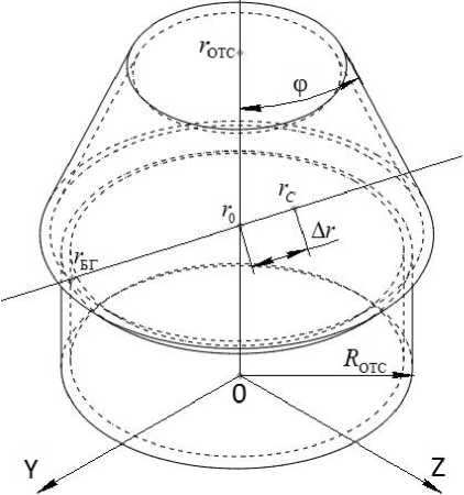
Рис. 1. Расчётная схема для определения ЦМ установки БГ
Fig. 1. Computational model for balancing weights (BW) center of gravity (COG) determination
The standard form of the equation of the centring line is xBW -xC=yBW -yC=zBW -zC⇒xBW -xC=yBW -yC=zBW -zC x0-xCy0-yCz0-zC∆rx∆ry∆rz
where r0 = ( x 0 y 0 z 0 ) T is the coordinate vector of the specified position of the spacecraft’s COG; r C = ( x C УС z C ) T is the coordinate vector of the current position of the spacecraft’s COG without BW; r BW = ( x BW y BW z BW ) T is the coordinate vector of the COG of the BW installation;
T
A r = ( A rx A ry A rz ) = r 0 - r C is the vector of deviations of the coordinates of the spacecraft’s COG without BW from the specified position.
Geometrically, the spacecraft’s compartment hull may take the form of a hypersurface – a combination of several segments of various elementary surfaces. For design purposes, the shapes of such segments of the spacecraft’s hull can be adequately described by surfaces of no higher than second order [12; 13]. In general form, the surface equation takes the form
U T AU + 2 bU + a 44 = 0,
where U = ( ux uy uz ) is the vector of coordinates of points on a segment of the spacecraft’s hull surface;
A =
a ll a 21
I a 31
b = ( a 14
a 12
a 22
a 32
a 24
a 13
a 23
a 33 J
is the affine matrix of coefficients for the quadratic term of the equation;
a 34 ) is the vector of coefficients for the linear term of the equation;
a jk : j , k = 1,4 is a set of coefficients for the equation of the spacecraft’s hull surface segment.
The coefficients of equation (2) are determined according to Table 1 [14], depending on the type of surface segment.
Table 1
Coefficients of the equation for a spacecraft hull surface segment
|
Surface |
a 11 |
a 22 |
a 33 |
a 14 |
a 24 |
a 34 |
a 44 |
|
Plane |
0 |
0 |
0 |
n x |
n y |
n z |
- ( n x x COMPT + ny y COMPT + n z z COMPT ) |
|
Sphere |
1 |
1 |
1 |
- x COMPT |
- y COMPT |
- z COMPT |
x 2 + y 2 + z 2 - R 2 COMPT y COMPT COMPT COMPT |
|
Cylinder |
0 |
1 |
1 |
0 |
- y COMPT |
- z COMPT |
y 2 + z 2 - R 2 y COMPT COMPT COMPT |
|
Cone |
tg 2 φ |
1 |
1 |
2 x COMPT tg ф |
- y COMPT |
- z COMPT |
7 7 7.7 y 2 + z 2 - x 2 tg2ф y COMPT COMPT COMPT g φ |
In Table 1, ( nx ny nz ) represents the cosines of the normal to the plane; r COMpT = ( x CoMpT y CoMpr z CoMPT ) represents the coordinates of a point on the plane, the centre of the sphere, the cylinder or the cone; RCOMPT represents the radius of the spacecraft’s compartment; φ represents the angle of the cone’s semi-apex.
The coordinates of the center of gravity (COG) of the BW assembly can be found using a vector transformation of the canonical equation of the centering line (1):
rBW = r0 + drArBW , (3) where dr = (X x Y) represents certain parameters of the centering line equation, depending on the shape of the spacecraft body surface segment; ArBW = (^ Z ?)T represents the deviations of the spacecraft’s COG coordinates (without BW) from the specified position, depending on the shape of the spacecraft body surface segment.
Substituting equation (3) into equation (2) produces quadratic equations in the unknown parameters of the centering line:
Z2X2 + 2 ( To - г С омрт ) Т & + R 2 = 0 - sphere,
* z2X2 + 2 r COMPT Zx + Р 2 = 0 - cylinder, (4)
ч 2 A Y 2 — 2 ? ( r COMn A — E ) Y + Q 2 = 0 — cone.
In system (4), the following convolutions are used for the equation on the sphere:
z x +%+^= ^ Т ^ =e,
( x o x COMPT ) Z x +( У 0 yCOMPT ) Z y +( z o z COMPT ) Z z = ( r o r COMPT ) Z,
_
x COMPT ) +( y 0 yCOMPT ) +( z 0
z COMPT ) ( R COMPT
h BWavg ) = ( r 0
_
r COMPT ) ( R COMPT
h BWavg
In system (4), the following convolutions are used for the equation on the cylinder:
0 + Z y + z 2 = z T z = z2,
0 + yCOMPT z y + z COMPT z z = r COMPT z ,
0 + y y COMPT
+ z
COMPT
_
COMPT
_
0 ,5 l BWavg )
= r COMPT
_
COMPT
_
0 ,5 l BWavg )
= P 2.
In system (4), the following convolutions are used for the equation on the cone:
ч 2 + ч У + ч 2 = ч T ч = ч 2,
(tg2ф 1 1)T=A, ч x ( xCOMPTtg ф - 1) + ч y ( yCOMPT -1) + ч z ( zCOMPT - 1) = ч ( rcOMPTA~E ),
/x 0 - x COMPT ) 2 t g2ф + ( y 0 - y COMPT ) 2 + ( z 0 - z COMPT ) 2 - 2 x COMPT t g2ф = ( r 0 - r COMPT ) 2 A - 2 R COMPT = Q 2 .
The roots of the equations in system (4) are
. -( r 0 - r COMPT ) Z ± JD sph .
X =------------2-------- sphere,
^
Т r ζ cyl h =--------- cylinder, (5)
z2
In each case, one of the two possible solutions in system (5) is selected based on the following criterion:
r BW ^ min. (6)
From the known equation of the COG of a spacecraft, we can derive a formula for estimating the total mass of the BW:
M bw = C M sc , (7)
r0 rBW where MSC is the mass of the spacecraft without BW.
The proposed approach to determining the coordinates of the center of gravity (COG) of the BW installation using Equation (3), with the coefficient values from (5) based on criterion (6) and the total mass of the BW calculated using equation (7), gives only an approximate result. As mentioned earlier, in reality, the surface on which the BW is placed is not smooth when BWs of different configurations are used. Therefore, the COG of the BW assembly will shift in the neighborhood along the centering line from the wall of the spacecraft compartment closer to the specified COG of the spacecraft without the BW. Consequently, the BW placement must be modeled in order to derive the final coordinates of the BW center points from the resulting electronic geometric model of the BW installation and then recalculate the spacecraft’s MCIC. To do this, first of all, one must identify available spaces in the neighborhood of the previously determined center of gravity of the BW installation.
Identification of the Configuration of the Balancing Weight Accommodation Zone
The balancing weight accommodation zone is a collection of spatial regions free from compartment structural elements and other components of the spacecraft. Generally, it can be separable and contain discontinuities.
During automated balancing weight placement, the configuration identification of the accommodation zone must also be automated to ensure the processing and use of model information for further actions. During this procedure, the boundaries of free regions along the surface of the spacecraft compartment body are determined, and the coordinates of points within these boundaries are stored at a specified interval.
The points of the structural elements on the surface of the spacecraft compartment body form a layer. Within this layer, points belonging to the boundaries of the BW accommodation zone are determined. They are connected by straight lines, thereby forming closed exclusion zones. The number of such zones is equal to the number of structural elements in a given area surrounding the BW installation's center of gravity, as the points in question possess attributes of belonging to specific electronic geometric models. By logically subtracting the exclusion zones from the surface of the BW accommodation zone, the available space for the payload installation is determined. Built-in procedures of CAD systems are used to check the space of the BW installation's intersections with its surroundings.
The sequence of steps described above is known as the Jarvis algorithm or method [15], according to which the points of interest are determined based on the following criterion:
cos v i + 1 = ( X + 1 - x i ) ( x i - 1 - x i ) + ( y i + 1 - y i ) ( y i - 1 - y i ) + ( z i + 1 - z i ) ( z i - 1 - z i ) ^ min, (8)
where ( x i - 1 y i - 1 z i - 1 ) is the coordinates of the second-to-last identified point; ( x i y i z i ) is the coordinates of the last identified point; ( x i + 1 y i + 1 z i + 1 ) is the coordinates of the next point to be identified; v i + 1 is the angle between the points in consideration.
The advantage of the Jarvis method, for example, over the Graham fast shell scan, is that it requires fewer calculations and is more convenient to use in three-dimensional space [16].
Coordinates of the placement of balancing weights
The identified BW placement area is delineated with a coordinate grid, the spacing of which is equal to the dimension lBWavg of the main BWs from the nomenclature. The markings should be made on the BW placement surface.
To minimize the overall BW mass by determining BW installation locations using the coordinate grid, the BW placement problem can be represented as a linear programming problem, where the objective function is
N BW
M BW = 2 m BWj ^ min, (9)
j = 1
where j = 1, NBW is the ordinal number of the BW; NBW is the number of all BWs; mBW j is the mass of the BW .
This objective function is subject to mass constraints depending on the available range of BWs used:
m BWj - 0, _ m BWj ^ max m BWj , where max mBW j is the maximum possible mass of BW according to the nomenclature.
In addition, the following centering constraints are imposed on the objective function (9):
N BW
M SC ( r 0 - min r 0 ) + 2 m BWj ( rBWj - min r 0 ) - 0, j = 1
N BW
M SC ( r 0 - max r 0 ) + 2 m BWj ( rBWj - max r 0 p 0, j = 1
where min r 0, max r 0 are the vectors of the boundary admissible values of the spacecraft's center of mass coordinates.
A linear programming problem with an objective function of the form (9) and constraints of the form (10) and (11) can be solved, for example, using the simplex method or the multiparametric Newton method [17]:
[ m BWj ] k + 1 =[ m BWj ] k - Hk ( M BW ) ^ к ( M BW ) , (12) where k is the ordinal number of the computational iteration; H — ( MBW ) is the inverse Hessian matrix of the objective function (9); V к ( MBW ) is the Nabla operator of the objective function (9).
For technical reasons, the obtained BW masses may be rounded to integer values. The grid point numbers at which the BW mass is nonzero are used to construct an electronic geometric model of the BW installation. It should be noted that BW units of different masses but identical overall dimensions lBW j will have different thicknesses hBW j . Therefore, if geometric intersections with structural elements occur, some BW units will need to be repositioned.
After that, the coordinates of the BW unit’s COG are recalculated to account for the fasteners using the formula rBW =
j
m BW j r BW j
+ mBWfastrBWfast
2 m BWj + m BWfast j
where m Bwfast is the mass of the fastener; r Bwfast = ( x bw fast y Bwfast z bw fast ) T is the coordinate vector of the fastener's COG.
When using adhesive and other permanent types of joints, the calculation using formula (13) is performed under the assumption that the layer of fastening material is distributed uniformly across the surface of the spacecraft compartment wall. The coordinates of the fastener’s center of mass are determined during simulation.
A general flowchart of the algorithm for placing BWs using formulas (1)–(13) is shown in Fig. 2. The list of required input data and their possible sources is presented in Table 2.
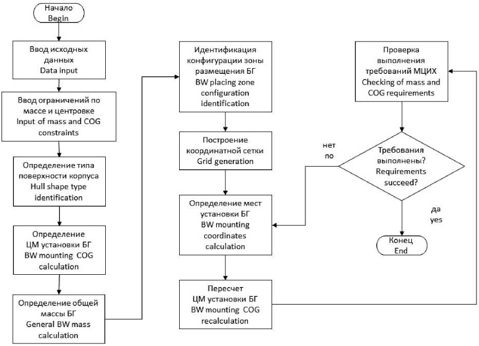
Рис. 2. Общая блок-схема алгоритма определения мест установки БГ
Fig. 2. Control flow chart for BW mounting places determination
Table 2
List of input data and their sources for the algorithm
|
Data Module |
Parameter |
Sources |
Collection options |
Processing methods |
|
Coordinates of the spacecraft’s COG at a specified position |
r 0 |
Explanatory note on spacecraft General types of spacecrafts |
Retrieving or entering information from DD |
Entering Retrieving |
|
Coordinates of the spacecraft’s COG at the current position, excluding the BW |
r C |
Calculation of MCIC of spacecraft Model of the spacecraft compartment Balancing rig |
Retrieving or entering information from DD Retrieving or entering from the model Retrieving or entering information from the rig |
Retrieving Calculation |
End of table 2
|
Coordinates of the geometric center of the compartment hull |
r COMPT |
General types of spacecrafts Model of the spacecraft compartment |
Retrieving or entering information from DD Retrieving or entering from the model |
Entering Retrieving |
|
Inner radius of the spacecraft compartment hull |
R COMPT |
General types of spacecrafts Model of the spacecraft compartment |
Retrieving or entering information from DD Retrieving or entering from the model |
Entering Retrieving |
|
Mass of the spacecraft, excluding the BW |
M SC |
Explanatory note on spacecraft General types of spacecrafts Calculation of MCIC of spacecraft Model of the spacecraft compartment Balancing rig |
Retrieving or entering information from DD Retrieving or entering from the model Retrieving or entering information from the rig |
Retrieving Calculation |
|
Average thickness of the BW from the nomenclature |
h BWavg |
DD on BW Model of the spacecraft compartment |
Retrieving or entering information from DD Retrieving or entering from the model |
Entering Retrieving |
|
Average dimensions of the BW from the nomenclature |
l BWavg |
DD on BW Model of the spacecraft compartment |
Retrieving or entering information from DD Retrieving or entering from the model |
Entering Retrieving |
|
Mass Constraints |
max mBW j |
Explanatory note on spacecraft |
Retrieving or entering information from DD |
Entering Retrieving |
|
Centering Constraints |
min r 0 max r 0 |
Explanatory note on spacecraft |
Retrieving or entering information from DD |
Entering Retrieving |
The method is implemented according to the algorithm presented in Fig. 2, in the following order of actions:
-
1. Determine (specify) the surface type of the spacecraft compartment body according to equation (2).
-
2. Calculate the coordinates of the COG of the BW installation using formulas (3)–(6).
-
3. Calculate the total mass of the BW using formula (7).
-
4. Construct the boundaries of the BW placement zone and the exclusion zones according to criterion (8) using the Jarvis method.
-
5. Construct a coordinate grid on the surface of the BW placement zone with a given step equal to the average BW size from the nomenclature.
-
6. Record the coordinates of the grid nodes as possible coordinates for the placement of the BW.
-
7. Set the maximum masses of the BW at all nodes of the coordinate grid.
-
8. Calculate the optimal masses of the payload at the coordinate grid nodes by solving the linear programming problem (9)–(11) using Newton's method (12) or the simplex method.
-
9. Taking into account the results of optimization and the mass of the fasteners, calculate the coordinates of the COG of the BW installation using formula (13).
-
10. Calculate the MCIC of the spacecraft layout.
-
11. Check that the conditions for the permissible deviations of the COG and the moments of inertia are met.
-
12. If the conditions in point 11 are not met, repeat points 6–11 of this procedure, taking into account the current optimization results.
-
13. If the conditions in point 11 are met, take the balancing result into account in subsequent calculations of the MCIC of the spacecraft compartment.
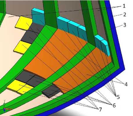
Рис. 3. Результаты определения мест установки БГ:
1 – внутренние стенки корпуса; 2 – сечение корпуса; 3 – конструкция;
4 – БГ тип 1 (массивные); 5 – БГ тип 2; 6 – БГ тип 3; 7 – БГ тип 4
-
Fig. 3. Results of BW mounting places determination:
-
1 – hull surface inside; 2 – hull sectional view; 3 – construction;
4 – BW type 1 (massive); 5 – BW type 2; 6 – BW type 3; 7 – BW type 4
Test Results
A conical spacecraft compartment with a spherical bottom was used as an example for testing. Calculations using formulas (2)–(6) revealed that the BW placement area should be located near the junction of the bottom and the hull shell. The configuration of the placement area was identified, taking into account the surrounding structural elements. The coordinates for the placement of the BWs were determined and their masses were selected. 9 of the 40 applied BWs needed to be moved to eliminate intersections with the structure. After this, the determination of the BW installation locations was completed, the coordinates of the COG of the BW installation center were recalculated, the MCIC of the spacecraft with the BW were also recalculated, and the fulfillment of the typical mass-centering and inertial requirements was ensured. To improve the assembly efficiency, 24 adjacent BWs were combined into monolithic massive BWs with complex geometry (topology). The simplified modeling results are shown in Fig. 3.
Conclusion
As a result of testing, the methodology for determining BW installation locations within the spacecraft compartment was refined. Electronic dimensional models of the simulated compartment and its structural elements were used for modeling. The degree of detail of the models will presumably impact the speed of the algorithm and the quality of the solution. Intersections with structural elements may occur when their detailed models are replaced by dimensional models, as well as if the surrounding elements do not belong to the payload placement surface. It is also necessary to shift BWs whose thickness does not equal the average value from the nomenclature.
Based on the placement results, the user can, at his own discretion, combine adjacent BWs into more massive BWs of any shape in order to reduce the labor intensity of their manufacture and installation. These actions may lead to deviations in the mass of the BW, therefore, after completing all transformations, it is recommended to recalculate the MCIC of the spacecraft. If the enterprise does not have a nomenclature of standardized BWs, then the most suitable dimensions of square BWs should be specified as initial data, guided by analogies from statistics. When modeling, it is necessary to take into account the variation in the mass of the BWs, so their models must be parameterized by thickness.
To determine the COG of the BW installation, identify the configuration of the BW placement zone, calculate the BW placement coordinates, and verify the requirements for the spacecraft's MCIC, one has to perform many mathematical operations. This method is advisable to use only when a specialized calculation software package is available, including modules for static and dynamic balancing.
Furthermore, it must be taken into account that the model of the BW installation obtained by the method must be supplemented with models of fasteners and other components. For issuing the DD, it will still be necessary to go through approvals regarding the surrounding structure and strength. Including auxiliary sections in the method to automate these stages makes no sense, because these simulation results are performed using special software products. Nevertheless, they are very useful when it is necessary to work out and discuss several options for BW placement before starting to prepare the DD.
Thus, as a result of the work performed, a method for determining the installation locations of BWs inside spacecraft compartments was developed and tested. Using the proposed algorithm, it is possible to ensure the minimum total mass of the BWs used. Simulation showed that in order to meet the requirements for the spacecraft's MCIC regarding allowable values of moments of inertia, dynamic balancing should be performed. In addition, some comments were identified regarding the particular procedures, the introduced assumptions, and the order of using this method. Nevertheless, the proposed approach allows reducing the labor intensity of developing the DD for BW installation by accelerated elaboration of various BW placement options, assessment of possible intersections with structural elements of the compartment and other surrounding equipment at the stages of preliminary design and working DD. Also, the possibility of organizing the process of transferring initial data from the balancing stand software is not excluded.