Microring Resonators Based on 6x6 Generalized Multimode Interference Structures using Silicon Waveguides for Photonic Applications

Author: Trung-Thanh Le, Cao-Dung Truong
Journal: International Journal of Intelligent Systems and Applications(IJISA) @ijisa
Article in issue: 6 vol.4, 2012.
Free access
In this paper, we would like to propose a new microring resonator structure based on 6x6 Generalized Mach Zehnder interferometer (GMZI) using silicon waveguides. It is showed that this new kind of the devices works as three separated microring resonators. This characteristic of the device leads to a variety of tasks important to optical communications, including switching, filtering, add-drop multiplexing, sensing and modulation. In our study, silicon waveguides are used for designing the proposed devices. The transfer matrix method (TMM) and the three dimensional beam propagation methods (3D-BPM) are used to optimally design the device.
Integrated optics, microring resonators, multimode interference (MMI) couplers, silicon waveguides
Short address: https://sciup.org/15010272
IDR: 15010272
Text of the scientific article Microring Resonators Based on 6x6 Generalized Multimode Interference Structures using Silicon Waveguides for Photonic Applications
Published Online June 2012 in MECS
Microring resonators (MRRs) have been used as basic building blocks for optical signal processing applications such as optical switches, filters, modulators, and adddrop multiplexers [1]. Almost all of the reported works on microring resonator structures have used directional couplers as coupling elements [2]. In order to meet a variety of requirements for high-speed signal processing, the coupling coefficient needs to be adjusted arbitrarily. In general, the gap of a directional coupler can be adjusted to meet this requirement. However, for applications requiring high quality factor Q of the resonators, i.e., for high speed operation, the separations between two waveguides in the directional coupler must be very small. As a result, high loss due to conversion loss of modes is occurred [3]. In addition, the directional coupler has a large size and small fabrication tolerance. Therefore, multimode interference (MMI) couplers can be used in microring resonator structures instead of directional couplers. Use of multimode interference couplers is very attractive to the design of high speed and integrated light wave circuits due to their advantages of compactness, ease of fabrication, large fabrication tolerance and ease of cascaded integration [4].
In the literature, microring resonators based on a 2x2 and 3x3 MMI coupler was reported [2, 5, 6]; however, not much work on microring resonators based on higher order multimode interference couplers (NxN MMI couplers) using silicon waveguides have been reported. In addition, silicon on insulator (SOI) technology is considered to be a very proposing platform that has the potential to produce low lost, high index contrast, and compact devices.
Therefore, the aim of this paper is to propose a novel microring resonator structure based on 6x6 MMI couplers for the first time. The most interesting characteristic of the proposed device is that the device acts as three separate microring resonators based on 2x2 MMI couplers. The control of critical coupling of these three microring resonators can be achieved by using three separate phase shifters. The proposed device can be used for optical switching, filtering, add-drop multiplexing and sensing applications. As an example, a realization of a three-channel add drop multiplexers is presented. In addition, by choosing the lengths of the microring waveguides, a triplexer used for the fiber to the home (FTTH) networks can be achieved. The transfer matrix method (TMM) and the three dimensional beam propagation method (3D-BPM) are used to optimally design the proposed device.
The paper is organized as follows: A description of the general theory behind the use of multimode structures to achieve new structures of microring resonators is presented in Section II. Optimal design of MMI based microring resonator structures and simulation results are covered in Section III. A brief summary of the results of this research is given in Section IV.
-
II. General Theory
A Mach-Zehnder microring resonator based on 6x6 MMI couplers (MZI-MMI) is shown in Fig. 1. The two 6x6 MMI couplers have the same width W and
3L п length LMM j = —- , where L = is the beat MM 2 п Po -Pi length of the MMI coupler. In order to achieve tunable devices and control the critical coupling [7], three phase shifters Аф1, Аф2 and Аф3 are used in the three arms. Alternatively, passive phase shifters could be used to provide a desired power splitting ratio.
In order to analyze the device, the transfer matrix of the identical MMI couplers needs to be derived first and then the total transfer matrix of the device can be determined.
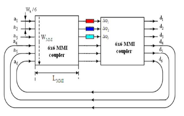
Fig. 1. Schematic of the Mach Zehnder microring resonators using 6x6 MMI couplers. Three phase shifters in three arms of the MZI are used to control critical coupling
The operation of optical MMI coupler is based on the self-imaging principle [8]. Self-imaging is a property of a multimode waveguide by which as an input field is reproduced in single or multiple images at periodic intervals along the propagation direction of the waveguide. The central structure of the MMI filter is formed by a waveguide designed to support a large number of modes. In the MMI section, the 2-D scalar Helmholtz wave equation is defined as
3L
LMM i = 2L2 = _^ , the MMI coupler is characterized
by a transfer matrix M. We can prove that the overall transfer matrix S of both the MMI coupler and combiner in Fig. 1 is expressed by
d V d 2 ф d x2 d y2
2 п n(x, y) X
v = P2v
M - 1
where v (x,y,z) = £ c vvv (x, y)exp(j( ro t - Pv z)) ; x is v = 0
the lateral dimension; y is the transverse dimension; z is the propagation direction; c is the filed excitation coefficient; yv (x,y) is the modal field distribution; n(x,y) is the refractive index profile, v =0, 1,..., M-1 are the mode numbers of the waveguide supporting M modes; X is the optical wavelength and p is the propagation constant.
If we choose the MMI coupler having a length of
S = MxM = 1
-e j 40
- -
0 ej4
. 3п ej4
3 j4
. 3п
0 00 e
. 3п
00 e
. п.3л e4e400
. 3п.п e4e400
- п
00 e
. п
0 00 e
This matrix can be considered as consisting of three separate sub-matrices which describe four 2x2 3dB
MMI couplers, both having the transfer matrix [9]
M
2 V2
e4
. 3п ej4
. 3п ej4
e4
= —i=e
п j 4
1 j
j
T 2 =
d2 a2
2 7 Аф2 „ Аф2
a2 + cos ^2 — 2 a2 cos _2 cos 9
АФ 2
, 2 2 Аф? „ Аф?
1 + a 2 cos2 ^2 — 2 a2 cos —t2 cos 9
АФ 2
Relations between the complex amplitudes a , a ,..., a at the input ports and d , d ,..., d at the output ports (see Fig. 1) can be expressed in terms of the transfer matrices of the 3dB MMI couplers and the phase shifters as follows
T 3 =
d3
a3
2 2 Аф3 , Аф3
a3 + cos —^-3- — 2 a3 cos^^3- cos 9
АФ з
, 2 2 Аф3 „ Аф3
1 + a3 cos —^3- — 2 a3 cos cos 9
АФ з
d1
d6
А Ф 1
= je 2
Т 1
*
К 1
К 1
*
—Т 1
a1
a6
d2
jA£ 2 Г
= je 2
т 2
*
К 2
К 2
*
—т 2
a2
a5
Here a 1 , a 2, and a 3 are round trip transmissions of light propagation through the three microring resonators [6] depending the losses of light propagation from output ports d d , d back to input ports a4, a5 , a5 ; for a lossless resonator a i = 1 (i=1, 2, 3) . The round trip
phases are given by: 9 1 = ^neff1L1 , 9 2 = ^ neff2L2 ,
d3
d 3
d 4 J
K 3
*
—T 3
a3
a4
where т 1 = sin( ^1), К = cos( ^1) ; т 2 = sin( Аф 2 ) ,
K2 = cos(^2) , T3 = sin(Аф3), K3 = cos(Аф3) ; are coupling coefficients of the MZI-MMI couplers; Аф], Аф2, Аф3 are the phase differences between two arms of the MZI, respectively.
Using the method similar to that presented in [1], the normalized optical intensity transmitted through the proposed device are then calculated by
2 п
9 3 = ~^neff3L3
where neff1, neff2, neff3 are the effective indices of the optical mode in the ring waveguides; L1, L2, L3 are the ring circumferences (or the lengths of the microring waveguides), and X is the optical wavelength.
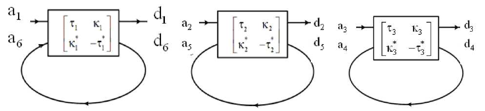
Therefore, the whole device can be viewed as consisting of three independent microring resonators having different coupling coefficients as shown in Fig. 2. This means that three independent switches and filters can be made by using this structure. One important and interesting characteristic of this structure applied is that the control of critical coupling for three microring resonators can be achieved separately.
T 1 =
d1 a1
a 2 + cos2 ^1 — 2 a]
1 21
Аф]
cos 1
cos 9!
2 2 Хф1_2..
1 ^i y.a c^^s a
Аф cos 1
cos 9 1
(a) MRR1 (b) MRR2 (c) MRR3
Fig. 2. Three separate microresonators created from the 6x6 MMI structures
(a) microring resonator using input ports 1 and 6 (MRR1) and
(b) microring resonators using input ports 2 and 5 (MRR2) and
(c) microring resonator using ports 3 and 4 (MRR3)
Another configuration of practical interest is presented in Fig. 3, where the second MZI microring resonator structure is also coupled to the first structure. The coupling ratios can be adjusted by the phase shifters
Δϕ 1, Δϕ 2, Δϕ 3, Δϕ 4, Δϕ 5, and Δϕ 6 . The 12 ports of this microring resonator are referred to input ports ( Ei1, Ei2, Ei3 ), through ports ( Et1, Et2, Et3 ), drop ports (Ed1, Ed2, Ed3) and add ports (Ea1, Ea2, Ea3) of
optical add-drop multiplexers.
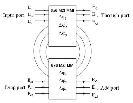
Fig. 3. Three separate add-drop multiplexers based on micro resonators using 6x6 MMI-MZI structures
The transmission powers at the output waveguides of the through ports of the add-drop multiplexers are given by
|
Pt1 = |
Et1 Ei1 |
2 |
τ 1 1 - |
- τ * 4 α 1 exp(j θ 1) τ 1 * τ * 4 α 1 exp(j θ 1) |
2 |
(10) |
|
|
Pt2 = |
E t2 Ei2 |
2 |
τ 2 1 - |
- τ * 5 α 2 exp(j θ 2) τ * 2 τ * 5 α 2 exp(j θ 2) |
2 |
(11) |
|
|
Pt3 = |
E t3 Ei3 |
2 |
τ 3 1 - |
- τ * 6 α 3 exp(j θ 3) τ * 3 τ * 6 α 3 exp(j θ 3) |
2 |
(12) |
|
The transmission powers at the output waveguides of the drop ports of the add-drop multiplexers are given by
Pd1 =
P d2 =
Pd3 =
E d1
Ei1
Ed2
E i2
*
-κ 1 κ 4
α 1 exp(j θ 1 /2)
**
1 - τ 1 * τ * 4 α 1 exp(j θ 1)
*
-κ 2 κ 5 α 2 exp(j θ 2 /2)
**
1 - τ 2 τ 5 α 2 exp( j θ 2)
Ed3
E i3
-κ * 3 κ 6 α 3 exp(j θ 3 /2)
**
1 - τ 3 τ 6 α 3 exp(j θ 3)
III. Simulation Results And Discussion
In this section, in order to verify the working principle of the devices and optimize the designs of MMI based devices, the three dimensional beam propagation method (3D-BPM) [10] is used in our study. It is well known that the finite difference time-domain (FDTD) method is a general method to solve Maxwell’s partial differential equations numerically in the time domain. Simulation results for devices on silicon waveguides using the 3D-FDTD method can achieve a very high accuracy. However, due to the limitation of computer resources and memory requirements, it is difficult to apply the 3D-FDTD method to the modeling of large devices on the silicon waveguide. Meanwhile, the 3D-BPM was shown to be a quite suitable method that has sufficient accuracy for simulating devices based on silicon waveguides [11].
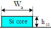
The silicon waveguide structure used in the designs is shown in Fig. 4, where SiO (n=1.46) is used as the upper cladding material. An upper cladding region is needed for devices using the thermo-optic effect in order to reduce loss due to metal electrodes. Moreover, the upper cladding region is used to avoid the influence of moisture and environmental temperature.
Upper cladding
SiO; cladding
Si Substrate by using the 3D-BPM first. Fig. 5(a) shows the normalized output powers at the bar and cross ports at different MMI lengths for a signal presented at input port 1 of the MMI coupler. From this simulation result, the optimized length of MMI calculated to be LMMI = 273.5µm . The field propagation through the 6x6 MMI coupler at this optimized length is plotted in Fig. 5(b). The BPM simulations of Fig. 5(b) show that our theory has predicted accurately the transfer matrix of the MZI-MMI coupler.
Fig. 4. Waveguide structure used in our designs
The parameters used in the designs are as follows: the waveguide has a standard silicon thickness of hco = 220nm and access waveguide widths are W = 0.48 µ m for single mode operation [12]. The refractive index of the silicon core is nSi = 3.45 . It is assumed that the designs are for the transverse electric (TE) polarization at a central optical wavelength λ = 1550nm . The width of the MMI is to be WMMI =8.4µm. The access waveguide is tapered to a width of W = 800nm to improve device performance.
The length of the 6x6 MZI-MMI coupler is optimized
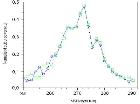
(a) Normalized output powers at different MMI lengths for input signal at input port 1 of the MZI-MMI coupler
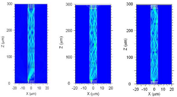
(b) Field propagation for input signal at port 1, port 2 and port 3
Fig. 5. BPM simulation results:
(a) normalized output powers at different lengths of the 6x6 MZI-MMI coupler and
(b) field propagation at the optimized MMI length for input signal at port 1, 2 and 3
The transmission spectrum of the microring resonators of Fig. 1 is shown in Fig. 6. The simulation parameters used in this study are: the width of the 6x6 MMI coupler WMMI =8.4µm, length of the 6x6 MMI coupler LMMI = 273.5 µ m , the lengths of microring waveguides L1 = 700 µ m , L2 = 800 µ m and L3 = 900 µ m and the loss factors α 1 = α 2 = α 3 = 0.98 . At this length of the MMI coupler, the microring resonators act as when the phase shifters in the MZI-MMI arms of the microring resonators are
Δϕ 1 = Δϕ 2= Δϕ 3 = 0 .The most interesting characteristic of this structure is that this device can simultaneously generate the transmission spectrum of three separate 2x2 microring resonators. In addition, if phase shifters Δϕ 1, Δϕ 2, Δϕ 3, Δϕ 4, Δϕ 5, and Δϕ 6 are used in the MZI-MMI arms to control the coupling coefficients κ , κ , and κ , the critical coupling condition [7] can be met. As a result, devices based on the proposed structure hold the promise of wavelength-selective switching, modulation and filtering applications.
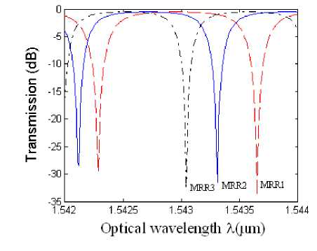
Fig. 6. Transmission spectrum of the proposed microring resonator.
The proposed structure acts as three separate 2x2 MMI based microring resonators
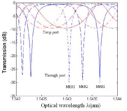
Fig. 7. Transmission spectrum of the microring resonators of Fig. 3. The proposed structure acts as three separate 2x2 microring resonator based add-drop multiplexers.
Fig. 7 shows the transmission of microring resonator add drop filters with the lengths of microring waveguides L1 = 700 µ m , L2 = 800 µ m and
L3 = 900 µ m and the loss factors α 1 = α 2 = α 3 = 0.98 . The simulation shows that this device can be used for implementation of a three-channel add drop multiplexer. In addition, reconfigurable add drop multiplexers
(ROADM) can also be achieved by controlling six phase shifters Δϕ 1, Δϕ 2, Δϕ 3, Δϕ 4, Δϕ 5, and Δϕ 6 .
Another possible application of the proposed structure is the realization of wavelength divison multiplexing (WDM) filters. Such devices are very useful in fiber to the home (FTTH) networks that provide triple-play (voice, data and video) services [13]. One of the most essential components in the FTTH networks for providing the triple-play services is the WDM filters. The WDM filter separate or combine optical signals with different wavelengths in a cost effective manner. Recently, many designs of triplexers have been proposed, including triplexer based on planar lens, gratings, multimode interference couplers, crytal photonics and cascaded MZIs [13]. However, most of the work reported is either based on low index contrast systems or directional couplers. In this study, an optical triplexer for splitting signals of three wavelengths
λ1= 1310nm, λ3= 1490nm, λ3 = 1550nm can be implemented using the proposed structure. By setting the appropriate lengths of the microring waveguides to L1 = 105µm , L2 = 179µm and L3 = 248µm , the transmission spectrum at three drop ports of the add drop filter is shown in Fig. 8. The lengths of the microring waveguides are chosen in order to satisfy the resonance condition, where the wavelength resonance is given by mmm
λ 1 = , λ 2 = , λ 3 = (16)
L 1 n eff L 2 n eff L 3 n eff
Here, m is an integer. It is obvious from the simulations that three separate filters having optical resonances at
λ 1 = 1310nm, λ 3 = 1490nm, λ 3 = 1550nm are obtained. As a result, the signal with three wavelengths λ 1, λ 2, and λ 3 incoming three input ports Ei1, Ei2 , Ei3 can be multiplexed at three drop ports Ed1, Ed2 , Ed3 and the triplexer can be achieved.
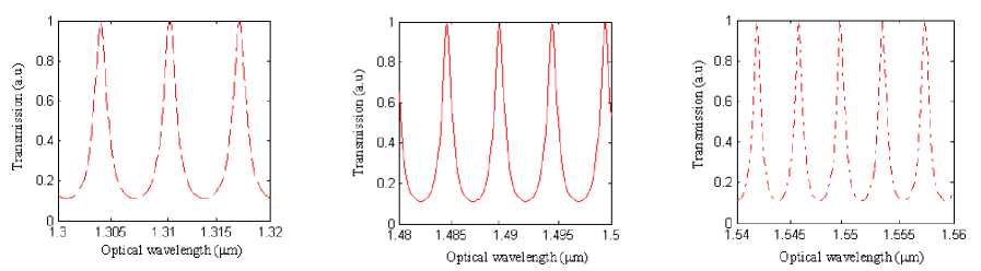
(a) MRR1, L 1 = 105 µ m
(b) MRR2, L 2 = 179 µ m
(c) MRR3, L 3 = 248.3 µ m
Fig. 8. Transmission spectrum of the microring resonators of Fig. 3. The proposed structure are used for a triplexer splitting the signal of three wavelengths λ 1 , λ 2 , and λ 3
-
IV. Conclusion
In summary, we have presented the design of a novel microring resonator structure based on 6x6 multimode interference couplers. The proposed device generated the transmission characteristics similar to that of three separate microring resonators based on 2x2 couplers. It has been shown that the proposed device can be used for promising applications in optical communications, including switching, filtering, multiplexing and modulation. In addition, a realization of a triplexer used for the FTTH networks has been presented. Devices have been designed using silicon waveguides. The transfer matrix method and beam propagation method have been used to optimally design the device and to investigate the device performance.
References Microring Resonators Based on 6x6 Generalized Multimode Interference Structures using Silicon Waveguides for Photonic Applications
- D. G. Rabus, Integrated Ring Resonators – The Compendium: Springer-Verlag, 2007.
- Dan-Xia Xu, A. Densmore, P. Waldron, J. Lapointe, E. Post, and A. Delâge, "High bandwidth SOI photonic wire ring resonators using MMI coupler," Optics Express, vol. 15, pp. 3149-3155, 2007
- F. Xia, L. Sekaric, and Y. A. Vlasov, "Mode conversion losses in silicon-on-insulator photonic wire based racetrack resonators," Optics Express, vol. 14, pp. 3872-3886, 2006
- T. T. Le and L. W. Cahill, "The modeling of MMI structures for signal processing applications," Integrated Optics: Devices, Materials, and Technologies XII. Edited by Greiner, Christoph M.; Waechter, Christoph A. Proceedings of the SPIE, vol. 6896, pp. 68961G-68961G-7, 03/2008.
- T.-T. Le and L. Cahill, "Microresonators based on 3x3 restricted interference MMI couplers on an SOI platform," presented at IEEE LEOS Annual Meeting Conference Proceedings (LEOS 2009), Belek-Antalya, Turkey, 4-8 Oct. 2009.
- W. Green, R. Lee, and G. D. e. al., "Hybrid InGaAsP-InP Mach-Zehnder Racetrack Resonator for Thermooptic Switching and Coupling Control," Optics Express, vol. 13, pp. 1651-1659, 2005.
- A. Yariv, "Critical coupling and its control in optical waveguide-ring resonator systems," IEEE Photonics Technology Letters, vol. 14, pp. 483-485, 2002.
- M. Bachmann, P. A. Besse, and H. Melchior, "General self-imaging properties in N x N multimode interference couplers including phase relations," Applied Optics, vol. 33, pp. 3905-, 1994.
- L. T. Thanh and L. Cahill, "The Design of 4×4 Multimode Interference Coupler Based Microring Resonators on an SOI Platform," Journal of Telecommunications and Information Technology, Poland, pp. 98-102, 2/2009.
- W. P. Huang, C. L. Xu, W. Lui, and K. Yokoyama, "The perfectly matched layer (PML) boundary condition for the beam propagation method," IEEE Photonics Technology Letters, vol. 8, pp. 649 - 651, 1996.
- D. Dai and S. He, "Design of an ultrashort Si-nanowaveguide-based multimode interference coupler of arbitrary shape," Applied Optics, vol. 47, pp. 38-44, 2008.
- T.-T. Le, Multimode Interference Structures for Photonic Signal Processing: Modeling and Design: Lambert Academic Publishing, Germany, 2010.
- D.-S. Park, J.-H. Kim, B.-H. O, S.-G. Park, E.-H. Lee, and S. G. Lee, "Optical Triplexer Based on a Photonic Crystal Structure with Position-Tuned Point Defects," Journal of the Korean Physical Society, vol. 54, pp. 2269-2273, June 2009.
