Modified Method for Denoising the Ultrasound Images by Wavelet Thresholding

Author: Alka Vishwa, Shilpa Sharma
Journal: International Journal of Intelligent Systems and Applications(IJISA) @ijisa
Article in issue: 6 vol.4, 2012.
Free access
Medical practitioners are increasingly using digital images during disease diagnosis. Several state-of-the-art medical equipment are producing images of different organs, which are used during various stages of analysis. Examples of such equipment include MRI, CT, ultrasound and X-Ray. In medical image processing, image denoising has become a very essential exercise all through the diagnosis as Ultrasound images are normally affected by speckle noise. The noise in the image has two negative outcomes, the first being the degradation of the image quality and the second and more important, obscures important information required for accurate diagnosis.Arbitration between the perpetuation of useful diagnostic information and noise suppression must be treasured in medical images. In general we rely on the intervention of a proficient to control the quality of processed images. In certain cases, for instance in Ultrasound images, the noise can suppress the information which is valuable for the general practitioner. Consequently medical images can be very inconsistent, and it is crucial to operate case to case. This paper presents a wavelet-based thresholding scheme for noise suppression in Ultrasound images and provides the knowledge about adaptive and anisotropic diffusion techniques for speckle noise removal from different types of images, like Ultrasound.
Ultrasound images, Medical imaging, Speckle noise, Wavelet Thresholding
Short address: https://sciup.org/15010268
IDR: 15010268
Text of the scientific article Modified Method for Denoising the Ultrasound Images by Wavelet Thresholding
Published Online June 2012 in MECS
Medical images are usually corrupted by noise in the process of acquisition and transmission. The main objective of Image denoising techniques is to remove such noises while retaining as much as possible the important diagnostic information. Introductory section offers a brief idea about different available denoising schemes.
-
A. Noise in an Image
It is generally desirable for image brightness (or film density) to be uniform except where it changes to form an image. There are factors, however, that tend to produce variation in the brightness of a displayed image even when no image detail is present. This variation is usually random and has no particular pattern. In many cases, it reduces image quality and is especially significant when the objects being imaged are small and have relatively low contrast. This random variation in image brightness is designated as noise. This noise can be either image dependent or image independent. All the digital images contain some visual noise. The presence of noise gives an image a mottled, grainy, textured or snowy appearance.
-
1) Random Noise
Random noise revolves around an increase in intensity of the picture. It occurs through color discrepancies above and below where the intensity changes. It is random, because even if the same settings are used, the noise occurs randomly throughout the image. It is generally affected by exposure length. Random noise is the hardest to get rid of because we cannot predict where it will occur. The digital camera itself cannot remove it and it has to be lessened in an image editing program.
-
2) Fixed Pattern Noise
Fixed pattern noise surrounds hot pixels. Hot pixels are pixel bits that are more intense than others surrounding it and are much brighter than random noise fluctuations. Long exposures and high temperatures cause fixed pattern noise to appear. If pictures are taken under the same settings, the hot pixels will occur in the same place and time. Fixed pattern noise is the easiest type to fix after it has occurred. Once a digital camera realizes the fixed pattern, it can be adjusted to lessen the effects on the image. However, it can be more dubious to the eye than random noise if not lessened.
-
3) Banding Noise
-
4) Speckle Noise
Speckle noise is defined as multiplicative noise, having a granular pattern. It is an inherent property of ultrasound image and SAR image. Another source of reverberations is that a small portion of the returning sound pulse may be reflected back into the tissues by the transducer surface itself, and generates a new echo at twice the depth. Speckle is the result of the diffuse scattering, which occurs when an ultrasound pulse randomly interferes with the small particles or objects on a scale comparable to that of the sound wavelength. The backscattered echoes from irresolvable random tissue inhomogenities in ultrasound imaging and from objects in Radar imaging undergo constructive and destructive interferences resulting in mottled b-scan image.
Speckle degrades the quality of US and SAR images and thereby reducing the ability of a human observer to discriminate the fine details of diagnostic examination. This artifact introduces fine-false structures whose apparent resolution is beyond the capabilities of imaging system, reducing image contrast and masking the real boundaries of the tissue leading to the decrease in the efficiency of further image processing such as edge detection, automatic segmentation, and registration techniques. Another problem in Ultrasound data is that the received data from the structures lying parallel to the radial direction can be very weak, as where structures normal to the radial direction give a stronger echo.
-
B. Filtering Techniques
Filtering techniques are used as preface action before segmentation and classification. On the whole speckle reduction can be divided roughly into two categories:
-
• Incoherent processing techniques
-
• Image post processing
The first one recovers the image by summing more than a few observations of the same object which suppose that no change or motion of the object happened during the reception of observations. These techniques do not require any hardware modification in the image reconstruction system, and hence have found a growing interest. In this the images are obtained as usual and the processing techniques are applied on the image obtained. Image post processing is an appropriate method for speckle reduction which enhances the signal to noise ratio while conserving the edges and lines in the image.
-
II. Speckle Noise in Ultrasound Images
These scans use high frequency sound waves which are emitted from a probe. The echoes that bounce back from structures in the body are shown on a screen. The structures can be much more clearly seen when moving the probe over the body and watching the image on the screen. The main problem in these scans is the presence of speckle noise which reduces the diagnosis ability. It provides live images, where the operator can select the most useful section for diagnosing thus facilitating quick diagnoses.
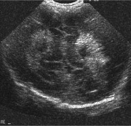
Fig 1 Ultrasound scans of normal prostate gland
Speckle noise affects all coherent imaging systems including medical ultrasound. Within each resolution cell a number of elementary scatterers reflect the incident wave towards the sensor. The backscattered coherent waves with different phases undergo a constructive or a destructive interference in a random manner. The acquired image is thus corrupted by a random granular pattern, called speckle that delays the interpretation of the image content.
Ultra Sound images have linear relationship between the local variance and mean of the speckle as hence it can be modelled as signal dependent noise.
ij ij ij . ij
Where Zij and Xij denote the pixel gray levels of the observed and true images, respectively, and the nij are noise terms independent of Xij.
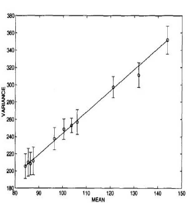
Fig 2. The linear relation between the local variance and mean of the speckle
III. Model of Speckle Noise
This signal dependent noise model helps us to smooth the image in the homogenous regions where the signal can be assumed to be constant. Using the parameter α, the local variance to mean ratio, it is possible to decide whether the processed pixel is within the homogenous region or not. Usually, if the local variance to the mean ratio is larger than the speckle, that corresponding pixel is considered as a resolvable object. Otherwise it is considered to be in homogenous region and is to be subjected to smoothening. Wavelet denoising attempts to remove the noise present in the signal while preserving the signal characteristics, regardless of its frequency content. As the discrete wavelet transform (DWT) corresponds to basis decomposition, it provides a non redundant and unique representation of the signal.
^ i, j
1W2
2 2 - m=-w/ m =-WZ
i,j
WW
= 2 2 2(X.-m,-n -M.)
W m = - W^ m = - W j
Where x i, j is the pixel at the location (i,j), W is the moving window size and it should be selected, so that neither window size is too small leaving out speckle from being filtered out nor it is too large so that over smoothening will occur causing blurring of edges and also if the window size is large, processor takes long time for filtering and thus causing problem in real time application. Fig 3. Real US noise free image Fig 4. Image with standard deviation of noise as 0.7
A. Wavelet Noise Thresholding
All the wavelet filters use wavelet thresholding operation for denoising. Speckle noise is a high-frequency component of the image and appears in wavelet coefficients. One widespread method exploited for speckle reduction is wavelet thresholding procedure. The basic Procedure for all thresholding method is as follows:
•
Calculate the DWT of the image
.
•
Threshold the wavelet coefficients. (Threshold may be universal or sub band adaptive)
•
Compute the IDWT to get the denoised estimate
.
•
There are two thresholding functions frequently used, i.e. a hard threshold, a soft threshold. The hard-thresholding is described as
П (w) = wI(| w Where w is a wavelet coefficient, T is the threshold. The soft-thresholding function is described as П (w) = ( w - sgn (w) T) I (| w |> T) (6) Where sgn(x) is the sign function of x. The soft-thresholding rule is chosen over hard-thresholding.
IV. Selection of Parameters
The parameter noise variances σ2 needs to be estimated first. It may be possible to measures σ2 based on information other than the corrupted image and it is estimated from the sub band HH1 by the robust median estimator, Weighted variance (δ) of a given wavelet coefficient is determined by the weight in a local window. The weight w2 corresponding to the vertical neighbours of the current coefficient is the most dominant one. The current coefficient to be processed is suppressed by choosing the corresponding weight w0 to be much lower than that of w2.This helps to distinguish between signal coefficients and noise coefficients. The selection of weights for the calculation of weighted variance would be in such a way that the estimated threshold minimizes the Mean square error. By some means the local weighted variance should reflect the correlation structure of wavelet coefficients. In general, magnitudes of wavelet coefficients show correlations, which decay exponentially with the distance. Also, in a 2-D wavelet decomposition, the decay depends strongly on the orientation o of the given band, i.e., along the direction of high pass filtering the correlation typically goes down more rapidly than in low pass direction. Also, the correlation depends on the level l of decomposition, such that on higher levels one observes a much stronger decay than on lower levels. By putting these observations together, we finally arrived at a model of weights.
V. Image denosing procedure
This section depicts the image-denoising algorithm, which achieves near optimal soft thresholding in the wavelet domain for recovering original signal from the noisy one. The wavelet transform employs Daubechies’ least asymmetric compactly supported wavelet with eight vanishing moments with four scales of orthogonal decomposition. It has the following steps.
•
Transform the multiplicative noise model into an additive one by taking the logarithm of the original speckled data.
•
Log I(x, y) = log S(x, y) + log n(x, y).
•
Perform the DWT of the noisy image up to 2 levels (L=2) to obtain seven sub bands, which are named as LL1, HH1, LH1, HL1, HH2, LH2, HL2 and LL2.
•
Obtain noise variance using 6.
•
Calculate the weighted variance of signal 5 by 4.
•
Compute the threshold value l for each pixel
by 5.
•
Threshold all sub band coefficients using Soft thresholding by substituting the threshold value obtained from 5.
•
Perform the inverse DWT to reconstruct the
denoised image.
•
Take Exponent.
VI. Experimental result and discussion
The performance of the wavelet thresholding method that has been proposed in this paper is investigated with simulations. Denoising is carried out for X-Ray image with Speckle noise of variance σ2 = 0.03, 0.04, 0.05, 0.06, 0.07 using standard speckle filters, Bayes thresholding, proposed thresholding and Wiener filter, the best linear filtering possible. The version used is the adaptive filter, wiener2, in the MATLAB image processing toolbox. For objective evaluation, the signal to noise ratio (SNR) of each denoised image has been calculated using Signal to Noise Ratio (SNR), which is defined as
SNR
=
10 log
Where
Ф
2
is the variance of noise free image and Г
Г
'
is the variance of error.
PSNR is the ratio between possible power of a signal and the power of corrupting noise that affects the fidelity of its representation. PSNR = 20 log,0 (255 / RMSE) N MSE = £[f(i,j)-F(i,j)] /N2
i
=
j
=
1
RMSE = V MSE(11)
Where X, Y represent the original and denoised images, respectively
.
VII. Conclusion and future Enhancement
The use of filter in Digital Image Processing improves the image to a great extent. Mainly in the case of presence of Speckle noise, filtering is very much required in order to improve the diagnostic examination and also to improve the efficiency of post processing techniques like segmentation.In this work we have introduced a relatively simple context-based model for adaptive threshold selection within a wavelet denoising framework. Estimations of local weighted variance with appropriately chosen weights are used to adapt the threshold. However, by visual inspection it is evident that the denoised image, while removing a substantial amount of noise, suffers practically node gradation in sharpness and details Experimental results show that our proposed method yields significantly improved visual quality as well as better SNR compared to the other techniques in the denoising literature. In future the best filter can automatically be selected using a lookup-table or by applying fuzzy rules after studying and using the image properties. Metrics like edges in the image, neural network can also be implemented to increase the filter optimization.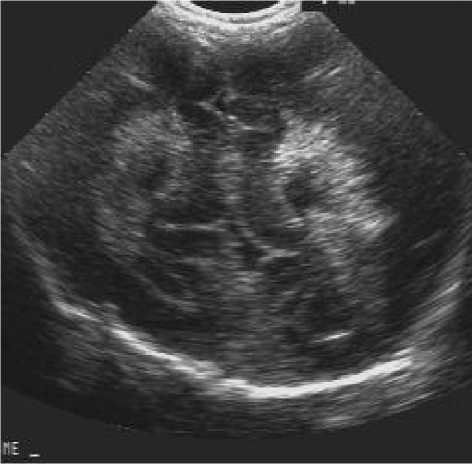
References Modified Method for Denoising the Ultrasound Images by Wavelet Thresholding
- C. B. Burckhardt. Speckle in Ultrasound B-Mode Scans. IEEE Transactions on Sonics and ultrasonics ,vol. 25, 1978, pp. 1 – 6.
- K. Tomiyas. Computer Simulation of Speckle in a Synthetic Aperture Radar Image Pixel, IEEE Transactions on Geoscience and Remote Sensing,vol. 21,1983,pp.357 – 363.
- M. O’Donnell and S. D. Silverstein. Optimum Displacement for Compound Image Generation in Medical Ultrasound. IEEE Transactions on Ultrasonics ferroelectronics and frequency control,vol. 35,1988,pp. 470-476.
- A. Lopes, R. Touzi and E. Nezry. Adaptive Speckle Filters and Scene Heterogeneity, IEEE Transactions on Geoscience and Remote Sensing, vol. 28,1990,pp. 992-1000.
- P. Perona, J. Malik . Scale-Space and Edge Detection Using Anisotropic Diffusion. IEEE Transactions on Pattern Analysis and Machine Intelligence,vol. 12, 1990,pp. 629-639.
- A. J. Healey, F. Forsberg and S. Leeman. Processing techniques for speckle reduction in medical ultrasound images. IEE Colloquium on Image Processing in Medicine,vol.6, 1991,pp. 1-4.
- E. Steen and B. Olstad. Volume Rendering in Medical Ultrasound Imaging based on Nonlinear Filtering. IEEE winter workshop on Nonlinear Digital Signal Processing, vol.6,1993,pp.1- 101.
- N. C. Richard, D. L. Jones and D. O. William. Ultrasound Speckle Reduction by Directional Median Filtering, IEEE International Conference on Image processing, vol.1,1995,pp. 358-361.
- M. Karaman, M. A. Kutay and G. Bozdagi. An Adaptive Speckle Suppression Filter for Medical Ultrasonic Imaging. IEEE Transactions on Medical Imaging, vol.14,1995,pp. 283-292.
- S. B. Jebara, Z. B. Hadj and H. Maatar. Combined Predictive and Multiresolution Schemes for Speckle Reduction in Radar Images. 6th IEEE International Conference on Electronics, Circuits and Systems,vol.2, 1999,pp. 965-968.
- M. P. Wachowiak and R. Smolikova. Classification and Estimation of Ultrasound Speckle Noise with Neural Networks. IEEE International Symposium on Bio-Informatics and Biomedical Engineering, 2000, pp. 245-252.
- C. Chinrungruen and A. Suvichakorn.Fast Edge-Preserving Noise Reduction for Ultrasound Images. IEEE Transactions on Nuclear Science, vol.48,2001, pp. 849-854.
- A. Achim, A. Bezerianos and P. Tsakalides. Novel Bayesian Multiscale Method for Speckle Removal in Medical Ultrasound Images. IEEE Transactions on Medical Imaging,vol.20, 2001, pp. 772-783.
- D. Mazumdar, S. Chatterjee, D. Roy and S. Mitra . Analysis and Statistical Characterization of Signal and Noise in Ultrasonography Images. http://www.kolkatacdac.in/downloads/technical%20papers/Ana_noise_filter_usg.pdf.
- C. Loizou, C. Christodoulou, C. S. Pattichis, R. Istepanian, M. Pantziaris and A. Nicolaides . Speckle Reduction In Ultrasound Images Of Atherosclerotic Carotid Plaque.IEEE 14th International Conference on Digital Signal Processing, vol. 2,2002, pp. 525- 528.
- Y. Yu and T. A. Scott. Speckle Reducing Anisotropic Diffusion. IEEE Transactions on Image Processing, vol. 11,2002, pp. 1260- 1270.
- S. T. Acton, J. A. Molloy and Y. Yu . Three-Dimensional Speckle Reducing Anisotropic Diffusion, IEEE Conference Record of the 37th Asilomar Conference on Signals, Systems and Computers, vol.2,2003, pp. 1987- 1991.
