Наблюдения ТГК «Прогресс» на оптическом телескопе АЗТ-33ИК

Автор: Клунко Е.В., Еселевич М.В., Тергоев В.И.
Журнал: Солнечно-земная физика @solnechno-zemnaya-fizika
Статья в выпуске: 3 т.2, 2016 года.
Бесплатный доступ
В работе приведено описание телескопа и измерительной аппаратуры, с помощью которых проводились оптические наблюдения транспортных грузовых кораблей (ТГК) «Прогресс» во время сеансов космических экспериментов «Радар-Прогресс». Приводится описание методик сопровождения объекта на низкой орбите и проведения измерений. Наблюдения проводились во время пролетов ТГК в зоне видимости оптического телескопа АЗТ-33ИК Саянской солнечной обсерватории ИСЗФ СО РАН. Во многих сеансах были зарегистрированы оптические явления, происходящие в окружающей ТГК области пространства и связанные с работой их бортовых двигателей. Полученные данные могут быть использованы для независимого контроля геометрии эксперимента и анализа физических условий во внешней среде. Приводятся примеры полученных изображений.
Космический эксперимент, оптический сигнал, космический аппарат, низкая орбита, телескопические наблюдения
Короткий адрес: https://sciup.org/142103607
IDR: 142103607 | УДК: 550.388.1 | DOI: 10.12737/20492
Текст научной статьи Наблюдения ТГК «Прогресс» на оптическом телескопе АЗТ-33ИК
The space experiment Radar-Progress is aimed at studying effects caused by engine running and fuel jets from spacecraft on Earth’s upper atmosphere and ionosphere [Khakhinov et al., 2012, 2013]. These effects were registered using active radio measuring equipment of ISTP SB RAS (the Irkutsk Incoherent Scatter Radar) [Lebedev et al., 2008; Potekhin et al., 2009] and passive radio and optical measuring equipment, which facilitated the subsequent complex analysis of acquired data.
The low Earth orbit of the Progress cargo spacecraft (PCS) (300–400 km above Earth’s surface) severely limits the time of its observation with the optical telescope. The spacecraft flies over the observation station for only a few minutes, with most night flights occurring so that the object is completely within Earth’s shadow and therefore invisible. Observations can be made only during a brief period of twilight when the Sun at an observation point is already below the horizon but still lights up the low-orbit spacecraft flying over the observatory. In the case of PCS, one-two passes per day meet these conditions. In many Radar-Progress space experiment sessions, engines of the PCS were started deliberately at certain moments to ensure its observation with the optical telescope. To provide the best visibility it is also essential that the PCS at such moments can be seen from the observation station at a sufficiently large height above the horizon (ideally, near the zenith).
Furthermore, the high visible velocity of spacecraft across the sky (1.5 °/s at the closest approach distance) hinders its proper tracking and keeping in the field of view of the optical telescope or, more precisely, of the optoelectronic system. This imposes strict requirements on the mechanics of the telescope, construction of its drives, control algorithms; and this becomes especially important if its field of view is only a few arcminutes.
Optical observations performed during the Radar-Progress space experiment were both supporting and independent. Observational data allowed us to control and recover geometrical parameters of the experiment (if unknown) and its time course, to measure parameters of the exhaust jet during engine running, to study its dynamics and jet—environment interactions.
Image resolution was limited by such factors as resolution of the optoelectronic system in hand, atmospheric seeing during observation, and image blur due to imperfect tracking. The angular size of the PCS at the closest approach distance of 300 km is 5 arcsec, thus only slightly exceeding the typical atmospheric seeing at the Sayan Solar Observatory (2 arcsec). Hence, even in the absence of other hampering factors, we cannot see details of images of the PCS itself without adaptive optics; therefore, we did not set the objective in this work. The emphasis was on taking images of engine and fuel jets, which had characteristic sizes far exceeding those of the PCS itself.
1. THE AZT-33IK OPTICAL TELESCOPE
The AZT-33IK telescope (Figure 1) is intended to observe near-Earth space objects (including low-orbit ones) and has a number of design features facilitating its effective use for these purposes. First, we should mention the high permissible rate of rotation about the polar and declination axes (up to 3 °/s). The telescope has a classical drive with worm gear, which guarantees high-precision motion of the telescope. The high speed in the worm gear is attained by special selection of materials: steel for the worm, fluoride bronze for the worm-wheel rim. In addition, the worm gear in the polar axis, which has a larger-sized wheel rim and, accordingly, higher speed of the worm relative to the wheel rim, is continuously lubricated by oil jet.
The drive of the AZT-33IK telescope has a single-motor design based on a high-torque stepper motor [Kamus et al., 2002]. One step of the engine corresponds to a 2 arcsec rotation of the telescope axis. The stepper motor provides the desired accuracy in setting the rate of the drive and thus the trajectory of the telescope in accordance with the calculated ephemeris of the spacecraft. The drive controller can also maintain the motor running in the microstepping mode. This is needed to improve the smoothness of rotation at low rates.
The maximum rotational acceleration about either axis of the telescope is 0.4 °/s2. This suffices to track a low-orbit spacecraft if the trajectory of its motion passes at a distance from the celestial pole. Since the telescope has an equatorial mount, it cannot make observations near the pole, where angular rates and accelerations of object tracking can tend to infinity. In general, the space experiment sessions were held on orbits on which the PCS trajectory was near the zenith, and tracking rates along the polar axis were within 2 °/s. Position of the telescope is controlled by encoders installed on the worm of each drive. Resolution of the encoder corresponds to the 0.15 arcsec rotation angle of the telescope along each axis.
In ten sessions of PCS observation, made with the telescope in 2010–2014, the maximum tracking rate along the polar axis ranged from 1.4 to 2 °/s, the rate along the declination axis was within 0.5 °/s. Maximum accelerations along the polar and declination axes did not exceed 0.04 and 0.03 °/с2 respectively.
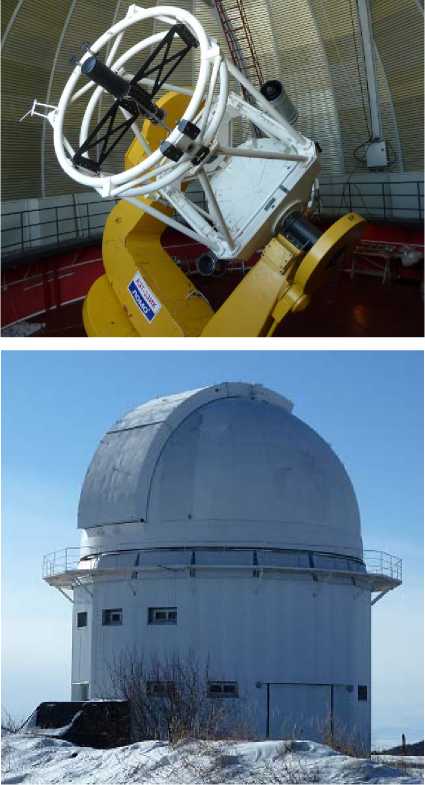
Figure 1. Outside appearance and the AZT-33IK telescope tower
The AZT-33IK telescope has the Ritchey–Chrétien design; the diameter of its primary mirror is 1.6 m. Its construction is optimized for observations in the IR spectral range. The main parameters of the telescope are listed in Table 1.
Table 1
The main parameters of the AZT-33IK optical telescope
|
mount |
equatorial fork |
|
maximum rate of motion |
3.0 °/s |
|
pointing error absolute/offset |
27/1.0 arcsec |
|
optical design |
Ritchey–Chrétien |
|
optical diameter of the primary mirror |
1600 mm |
|
optical diameter of the secondary mirror |
210.5 mm |
|
focal length |
30000 mm |
|
angular field of view |
12 ′ |
|
linear field of view |
105 mm |
Table 2
Parameters of the wide-field visible-range optoelectronic system
|
optical design |
catadioptric lens with Cassegrain focus |
|
diameter of the entrance pupil |
200 mm |
|
focal length |
250 mm |
|
CCD camera |
VS-CTT-423 |
|
CCD sensor |
ICX423AL |
|
full size of the CCD sensor |
744×572 pixel |
|
pixel size |
11.6×11.2 um |
|
digitizing bit depth |
12 bit |
|
field size |
2.0×1.5° |
|
maximum exposure time |
20 s |
|
limiting magnitude |
13 |
Table 3
Parameters of the main visible-range optoelectronic system
|
optical design |
mirror telescope with a focal reducer |
|
diameter of the entrance pupil |
1600 mm |
|
focal length |
6876 mm |
|
camera |
Andor Neo |
|
sensor |
sCMOS |
|
full size of sensor |
2560×2160 pixel |
|
pixel size |
6.5×6.5 um |
|
digitizing bit depth |
16 bit |
|
field size |
8.3×7.0 arcmin |
|
limiting magnitude |
22 |
|
filters |
BVRI |
2. MEASURING EQUIPMENT
In the space experiment sessions, optical signals were registered using the following optoelectronic systems installed in the AZT-33IK telescope:
-
• wide-field visible-range optoelectronic system
-
• main visible-range optoelectronic system
-
• IR 8–10 um range optoelectronic system [Tergoev et al., 2011].
The wide-field visible-range optoelectronic system consists of a PDNK lens and a CCD camera VS-CTT-423, which are fixed on the mount of the telescope. Parameters of this system are given in Table 2.
The main visible-range optoelectronic system includes an optical system of the AZT-33IK telescope (Cassegrain focus), a focal reducer, and a sCMOS camera Andor Neo. Parameters of this system are listed in Table 3. Measurements were largely made in the 4×4 pixel binning mode. Thus, one combined pixel was 26 um. This corresponds to 0.78 arcsec in the sky with respect to the focal length of the system.
The IR 8–10 um range optoelectronic system comprises the optical system of the AZT-33IK telescope (Cassegrain focus) and the IR 8–10 um range camera based on a matrix CdHgTe photodetector. Parameters of this system are presented in Table 4.
The optical system of the AZT-33IK telescope, which features the primary and secondary mirrors, is exploited in two optoelectronic systems – the main visible-range optoelectronic system and the IR 8–10 um optoelectronic system.
Table 4
Parameters of the IR 8–10 um range optoelectronic system
|
optical design |
Ritchey–Chrétien |
|
diameter of the entrance pupil |
1600 mm |
|
Equivalent focal length |
6874.5 mm |
|
focal ratio |
1:4.27 |
|
field of view |
0.1° |
|
pixel scale |
0.9 arcsec / pixel |
|
spectral range |
7.7–9.5 um |
|
CCD sensor |
CdHgTe (cadmium– hydrargyrum–tellurium) |
|
Cooling |
~77 K (liquid nitrogen) |
|
CCD-sensor size |
320×256 pixel |
|
pixel size |
30×30 um |
|
digitizing bit depth |
14 bit |
|
Adjustable exposure time |
15–700 µs |
|
frame readout time (5 MHz sampling frequency) |
5 ms |
|
time to transfer frame to PC |
≈ 50 ms |
|
controller memory |
128 frames |
The light flux is switched back and forth between them with the aid of a rotating diagonal mirror. Light falls on this mirror after passing through the hole in the primary mirror. It takes us 20–40 s to turn the mirror; therefore, we cannot utilize both the systems simultaneously during one space experiment session.
3. SPACECRAFT TRACKING METHOD
During the Radar-Progress space experiment, we devised and refined the method of observing low-orbit spacecraft with the optical telescope. In particular, we solved the problem of accurate tracking of a high-speed object. This method is successfully adopted to track other spacecraft in the low Earth orbits.
Tracking any moving object requires us to know its trajectory in the sky (ephemeris) for in-situ observations on Earth’s surface. Ephemeris is usually calculated from orbital elements of a spacecraft under study. In fact, a low-orbit spacecraft is affected by a large number of disturbing factors, i.e., its orbit changes rapidly. Therefore, PCS orbital elements were renewed every day by specialists from the Ballistic Analysis Center of TSNIIMASH. In the space experiment sessions, we computed PCS ephemerides, using the Apex-II software package [Devyatkin et al., 2010]
Note that during some spacecraft observations, ephemeris can also be formed dynamically from real-time data (for example, from results of simultaneous radar measurements of a space object). Furthermore, we can promptly update the ephemeris to bring the object to the center of the field of view or to compensate the rate of object drift away from the field of view. An example of such a correction can be the command “shift to the center” sent from the control program of the CCD camera [Klunko, Eselevich, 2012].
Note that without prior information about the trajectory of a low-orbit spacecraft it is rather difficult to track it with the optical telescope having a limited field of view (~1°). Spacecraft velocity can be up to 1.5 °/s, and the limited field of view of the telescope precludes registration of direction of spacecraft motion with accuracy sufficient for its further tracking along the trajectory.
The calculated ephemeris represents a sequence of apparent spacecraft positions in a celestial coordinate system (in our case, ICRS). In turn, pointing and tracking algorithms work in terms of instrumental coordinates and rates, i.e., coordinates read from the telescope’s encoders and rates sent to its drive controllers. Therefore, we should transform the ephemeris from ICRS to the instrumental coordinate system. This transformation is made in the telescope control program during any observation (not only of low-orbit spacecraft) and involves the following stages:
-
• transformation to an apparent place (with correction for precession, nutation, annual aberration, etc., as well as for Earth’s rotation);
-
• correction for refraction;
-
• correction for mechanical model of telescope pointing (error in installing the mount, misalignment of the polar and declination axes, fork flecture, tube flecture, etc. [ http://www.tpointsw.uk/index.htm ]). This ensures an all-sky telescope pointing accuracy of about 30 arcsec.
The process of pointing the telescope to the instrumental ephemeris and its motion are carried out in the control program in two stages called pointing and tracking phases. In this case, we employ somewhat different methods of calculating rates for the telescope’s drives. The pointing and tracking algorithm is an iterative (with a step on the order of 0.5–1 s) calculation of the telescope’s rates of motion v t and v δ in the polar and declination axes. Each iteration of the algorithm involves the following general stages:
-
• reading current values from the telescope’s encoders xt and xδ;
-
• determining the current angular position and velocity of the object from the ephemeris, converting them into instrumental (i.e., corresponding to the encoders) coordinates ( X t , X δ ) and velocities ( V t , V δ ) of the object (with time interpolation);
-
• calculating new rates of motion v t and v δ from differences between the instrumental coordinates ( x–X ) t, δ and the rates ( v–V ) t, δ of the telescope and the object (this calculation is different for pointing and tracking phases);
-
• sending the calculated rates v t and v δ to the telescope’s drive controllers.
The rate calculation algorithm in the pointing phase intends to the fastest possible pointing of the telescope to an object such that the telescope’s rate of motion at the final stage of the pointing synchronizes with that of the object. The pointing algorithm in each of the axes can more simply be represented as a speedup in the direction of the object, steady motion at a high rate, and slowdown to the velocity of the object (Figure 2). The pointing phase is considered completed after the target is acquired with a specified accuracy (in general, on the order of several arcminutes). During the tracking phase, the telescope’s rates of motion are corrected much more gradually to prevent abrupt shifts of the object in the field of view of the measuring system. In many cases, the simplest variant v t , δ =V t , δ works well (set the telescope’s rates of motion equal to current velocities of the object).
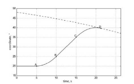
Figure 2 . Telescope pointing along one axis. Speedup (segment A–B), maximum rate of motion (B–C), slowdown to the velocity of the object (C–D). Variation of coordinate of the object is depicted by the dashed line
On position of the dome of the AZT-33IK telescope during PCS observations . In all the sessions, the PCS trajectory passed near the zenith, from west to east. In this case, the dome’s rate of rotation appears to be insufficient to observe the object throughout the pass. Therefore, before observation the dome was set along the PCS trajectory, i.e., westward or eastward (according to where – before or after the zenith – onboard engines were started), and this position was not changed throughout the period of observation.
In Figure 3, thick lines schematically show the dome and its slit (top view); the dashed line indicates the projection of the PCS trajectory. In some sessions, the telescope could start tracking the PCS according to the ephemeris blindly, with the object being still obstructed by the dome (point A). Thus, the telescope had begun tracking by the moment of engine start (segment B).
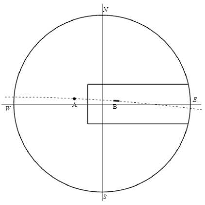
Figure 3. A position of the dome of the AZT-33IK telescope during PCS observation (top view)
4. IMAGE ACQUISITION
The observations aimed at registering an optical signal from the PCS engine jet in visible and infrared ranges, and at determining geometrical and brightness characteristics of the jet depending on time. Virtually in all the space experiment sessions, we employed the wide-field optoelectronic system and often the main visible-range system. The IR 8–10 um range system was exploited in the sessions of April 22–25, 2011, with no optical signals detected then. This may be due to both the inaccuracy in PCS tracking, i.e., missing it in the narrow field of view of the IR-range system (1 arcmin), and rather low sensitivity of the detection system itself – the detection threshold (the signal-to-noise ratio = 3) of the camera is –1 magnitude in the photometric band N (8–13.5 um) per 1 s exposure.
Exposures in different sessions for the wide-field system were 0.2–0.5 s; for the main system, 0.05–1.0 s (long exposures were used in the presence of clouds). The choice is determined by observational experience and is a compromise between the endeavors, on the one hand, to receive a sufficiently intense signal from low-contrast extended objects and, on the other hand, to observe dynamics of the process with high temporal resolution and to reduce image blur, caused by tracking errors.
For the IR-range system, we summed up each 20–25 frames at a single-frame exposure 200–250 μs.
During the observations, we sometimes used the R optical filter in the main system.
Captured images were written to a disk as FITS files; the start time of exposure was appended to the header of each frame. Time synchronization was carried out using a GPS synchronization system. Time synchronization accuracy was higher than 20 ms.
Images captured in different sessions exhibited diverse optical phenomena which occurred when the onboard engine worked (Figure 4) and when it was cut off, during the purging process (Figure 5). Generalized characteristics and parameters of received optical signals are given in [Eselevich, Klunko, 2016].
CONCLUSION
The optical signal from the Progress spacecraft in the Radar–Progress space experiment was received with the AZT-33IK telescope at the Sayan Solar Observatory of ISTP SB RAS. Technical parameters of the telescope and its control system facilitate tracking of low-orbit spacecraft during its passage over the observation station.
The main requirement imposed on the optical telescope for observations of low-orbit spacecraft is the capability of precision pointing and tracking of the object according to the calculated ephemeris; velocity of the object relative to stars in the sky may be as high as 1.5 °/s. The pointing and tracking algorithm should be implemented in such a way that the observed spacecraft remains in the field of view of the telescope and moves smoothly, without abrupt shifts. This enables us to detect the optical signal from the spacecraft and other optical effects during the space experiment. The estimated trajectory of spacecraft is not absolutely exact, hence the need for real-time correction of spacecraft position in the field of the telescope by specifying low additional rates of motion 29
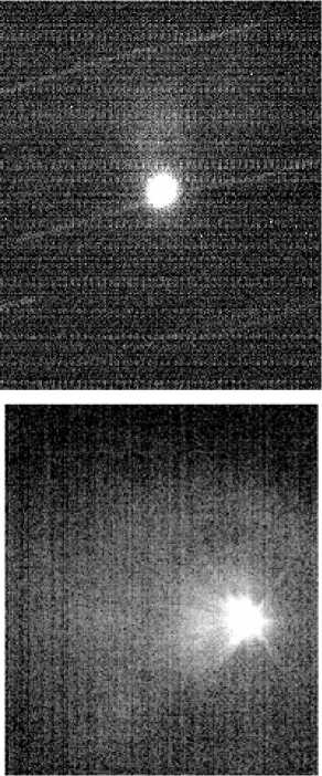
Figure 4 . Low-contrast cloud at the moment of PCS engine start in the wide-field (at the top) and main optoelectronic
systems
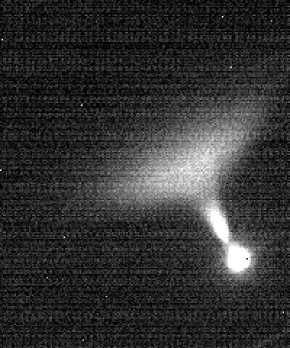
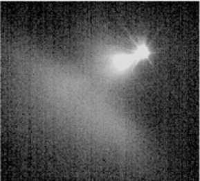
Figure 5 . Images of the fuel jet accompanying the purging process in the wide-field (at the top) and main optoelectronic
systems
and shifts relative to the calculated ephemeris. The pointing and tracking algorithm implemented to control the mount of the AZT-33IK telescope allowed routine optical observations during the Radar-Progress space experiment, thus providing detailed images of the region surrounding the PCS in a time interval of ~ 1 min. The use of cameras with electronic shutter and fast frame readout minimizes image blur caused by residual inaccuracy in spacecraft tracking and possible oscillations of the telescope tube, which occur as the telescope moves.
In many observational sessions, we observed optical effects associated with onboard engine ignitions as well as with the purging process when the engine was cut off. The images we took can be used to independently control geometry of the experiment and to analyze physical conditions in outer space.
Список литературы Наблюдения ТГК «Прогресс» на оптическом телескопе АЗТ-33ИК
- Девяткин А.В., Горшанов Д.Л., Куприянов В.В., Верещагина И.А. Программные пакеты «АПЕКС-I» и «АПЕКС-II» для обработки астрономических ПЗС-наблюдений//Астрономический вестник. 2010. Т. 44, № 1. С. 74-87.
- Еселевич М.В., Хахинов В.В., Клунко Е.В. Параметры оптических сигналов на телескопе АЗТ-33ИК, зарегистрированных в активном космическом эксперименте «Радар-Прогресс»//Солнечно-земная физика. 2016. Т. 2, № 3. С. 24-32.
- Камус С.Ф., Тергоев В.И., Папушев П.Г. и др. Широкодиапазонный астрономический телескоп//Оптический журнал. 2002. Т. 69, № 9. С. 84-87 DOI: 10.1364/JOT.69.000674
- Клунко Е.В., Еселевич М.В. Распределенная система управления астрономическими ПЗС-камерами//Солнечно-земная физика. 2012. Вып. 20. С. 139-145.
- Лебедев В.П., Хахинов В.В., Габдуллин Ф.Ф. и др. Исследование методами радиозондирования характеристик плазменного окружения низкоорбитальных космических аппаратов//Космонавтика и ракетостроение. 2008. № 50 (1). С. 51-60.
- Тергоев В.И., Еселевич М.В., Клунко Е.В. и др. Разработка и применение ИК-камеры для регистрации тепловых портретов космических аппаратов//Вестник Сибирского государственного аэрокосмического университета им. академика М.Ф. Решетнева. 2011. Вып. 6 (39).
- Хахинов В.В., Потехин А.П., Лебедев В.П. и др. Результаты дистанционного зондирования ионосферных возмущений в активных космических экспериментах «Радар-Прогресс»//Современные проблемы дистанционного зондирования Земли из космоса. 2012. Т. 9, № 3. С. 199-206.
- Хахинов В.В., Потехин А.П., Лебедев В.П. и др. Некоторые результаты активных космических экспериментов «Плазма-Прогресс» и «Радар-Прогресс»//Вестник Сибирского государственного аэрокосмического университета им. акад. М.Ф. Решетнева. 2013. Спец. вып. 5 (51). С. 160-163.
- Potekhin A.P., Khakhinov V.V., Medvedev A.V., et al. Active Space Experiments with the use of the transport spacecraft “Progress” and Irkutsk IS Radar//PIERS Proc. Moscow, 2009. P. 223-227.
- URL: http://www.tpointsw.uk/index.htm (дата обращения 1 июля 2016 г.).
